Page 416 of 510
5 - 26
CHASREAR WHEEL AND REAR BRAKE
REMOVAL POINTS
EC523101
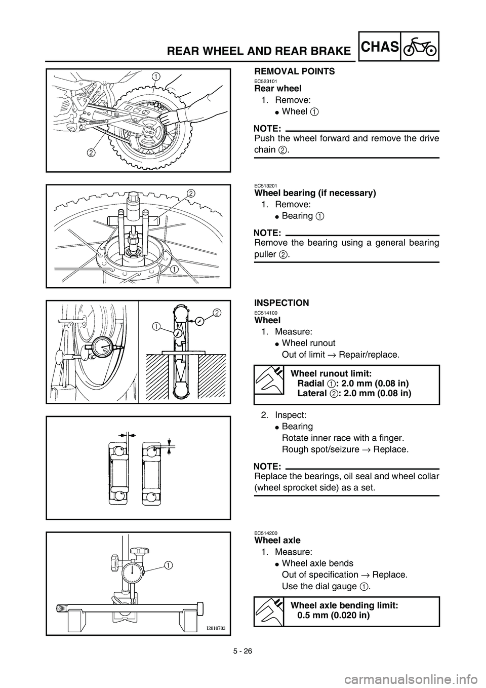
Rear wheel
1. Remove:
�Wheel 1
NOTE:
Push the wheel forward and remove the drive
chain 2.
EC513201
Wheel bearing (if necessary)
1. Remove:
�Bearing 1
NOTE:
Remove the bearing using a general bearing
puller 2.
INSPECTION
EC514100
Wheel
1. Measure:
�Wheel runout
Out of limit → Repair/replace.
2. Inspect:
�Bearing
Rotate inner race with a finger.
Rough spot/seizure → Replace.
NOTE:
Replace the bearings, oil seal and wheel collar
(wheel sprocket side) as a set.
Wheel runout limit:
Radial 1: 2.0 mm (0.08 in)
Lateral 2: 2.0 mm (0.08 in)
EC514200
Wheel axle
1. Measure:
�Wheel axle bends
Out of specification → Replace.
Use the dial gauge 1.
Wheel axle bending limit:
0.5 mm (0.020 in)
Page 417 of 510
 5 - 26
CHAS
ROUE ARRIÈRE ET FREIN ARRIÈRE
HINTERRAD UND HINTERRADBREMSE
DEMONTAGEPUNKTE
Hinterrad
1. Demontieren:
�Rad 1
HINWEIS:
Rad nach vorne drehen und Antriebskette 2
entfernen.
Radlager (fall")
5 - 26
CHAS
ROUE ARRIÈRE ET FREIN ARRIÈRE
HINTERRAD UND HINTERRADBREMSE
DEMONTAGEPUNKTE
Hinterrad
1. Demontieren:
�Rad 1
HINWEIS:
Rad nach vorne drehen und Antriebskette 2
entfernen.
Radlager (falls erforderlich)
1. Demontieren:
�Lager 1
HINWEIS:
Lager mit einem herkömmlichen Lageraustrei-
ber 2 demontieren.
PRÜFEN
Rad
1. Messen:
�Max. Schlag
Unvorschriftsmäßig → Reparieren/
erneuern.
2. Prüfen:
�Lager
Inneren Lagerlaufring mit einem Finger
drehen.
Rauheit/Lager fest → Erneuern.
HINWEIS:
Lager, Dichtringe und Paßhülse (Radnaben-
seite) satzweise erneuern.
Maximal zulässiger Schlag
Max. Höhenschlag 1: 2,0 mm
Max. Seitenschlag 2: 2,0 mm
Radachse
1. Messen:
�Radachsenbiegung
Unvorschriftsmäßig → Erneuern.
Meßuhr 1 verwenden.
Maximal zulässige Achsbiegung
0,5 mm
PIÈCES À DÉPOSER
Roue arrière
1. Déposer:
�Roue 1
N.B.:
Pousser la roue vers l’avant et déposer la chaîne de
transmission 2.
Roulement de roue (si nécessaire)
1. Déposer:
�Roulement 1
N.B.:
Déposer le roulement à l’aide de l’extracteur de
roulements universel 2.
CONTRÔLE
Roue
1. Mesurer:
�Déformation de la roue
Hors spécifications → Réparer ou rempla-
cer.
2. Examiner:
�Roulement
Faire tourner la cage interne à l’aide d’un
doigt.
Dureté/grippage → Remplacer.
N.B.:
Remplacer les roulements, la bague d’étanchéité et
le collier de roue (côté pignon de roue) en même
temps.
Limite de voile de roue:
Radial 1: 2,0 mm (0,08 in)
Latéral 2: 2,0 mm (0,08 in)
Axe de roue
1. Mesurer:
�Déformations de l’axe de roue
Hors spécifications → Remplacer.
Utiliser un comparateur à cadran 1.
Limite de déformation d’axe de roue:
0,5 mm (0,020 in)
Page 420 of 510
5 - 28
CHASREAR WHEEL AND REAR BRAKE
4. Inspect:
�Brake drum inner surface.
Oil/scratches → Remove.
OilUse a rag soaked in lac-
quer thinner or a solvent.
ScratchesUse a emery cloth (lightly
and evenly polishing).
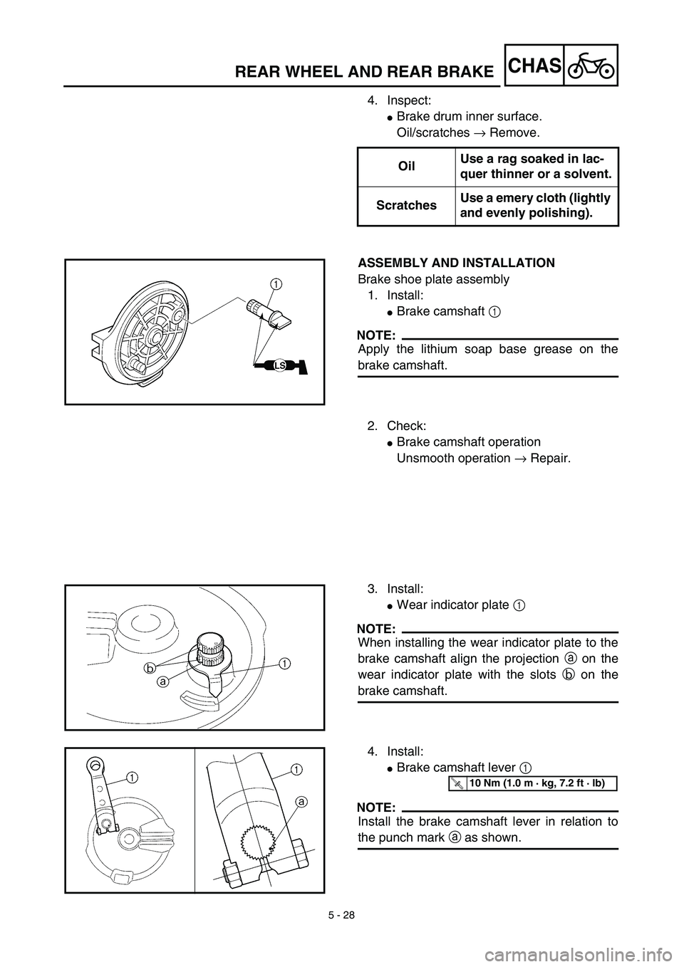
ASSEMBLY AND INSTALLATION
Brake shoe plate assembly
1. Install:
�Brake camshaft 1
NOTE:
Apply the lithium soap base grease on the
brake camshaft.
2. Check:
�Brake camshaft operation
Unsmooth operation → Repair.
3. Install:
�Wear indicator plate 1
NOTE:
When installing the wear indicator plate to the
brake camshaft align the projection a on the
wear indicator plate with the slots b on the
brake camshaft.
4. Install:
�Brake camshaft lever 1
NOTE:
Install the brake camshaft lever in relation to
the punch mark a as shown.
T R..10 Nm (1.0 m · kg, 7.2 ft · lb)
Page 421 of 510
 5 - 28
CHAS
4. Kontrollieren:
�Bremstrommel-Oberfläche (innen)
Öl/Kratzer → Entfernen.
ZUSAMMENBAU UND MONTAGE
Bremsankerplatte
1. Montieren:
�Bremsnocken 1
HINWEIS:
Lithiumfett auf Bremsnocken a")
5 - 28
CHAS
4. Kontrollieren:
�Bremstrommel-Oberfläche (innen)
Öl/Kratzer → Entfernen.
ZUSAMMENBAU UND MONTAGE
Bremsankerplatte
1. Montieren:
�Bremsnocken 1
HINWEIS:
Lithiumfett auf Bremsnocken auftragen.ÖlEinen mit Verdünner oder
einem Lösungsmittel
getränkten Lappen ver-
wenden.
KratzerSchmirgelleinen verwen-
den (vorsichtig und
gleichmäßig polieren).
2. Prüfen:
�Bremsnocken-Betätigung
Schwergängigkeit → Reparieren.
3. Montieren:
�Verschleißanzeiger 1
HINWEIS:
Bei der Montage des Verschleißanzeigers auf
der Bremsnockenwelle die Nase a des Ver-
schleißanzeigers auf die Kerben b der
Bremsnockenwelle ausrichten.
4. Montieren:
�Bremsnocken-Betätigungshebel 1
HINWEIS:
Den Bremsnocken-Betätigungshebel in bezug
auf die Stanzmarkierung a montieren, wie in
der Abbildung gezeigt.
T R..10 Nm (1,0 m · kg)
ROUE ARRIÈRE ET FREIN ARRIÈRE
HINTERRAD UND HINTERRADBREMSE
4. Examiner:
�Surface intérieure du tambour de frein.
Taches d’huile/rayures → Éliminer.
REMONTAGE ET INSTALLATION
Ensemble flasque de frein
1. Installer:
�Came de frein 1
N.B.:
Enduire la came de frein de graisse à base de savon
au lithium.HuileSe servir d’un chiffon
imbibé de diluant pour pein-
ture ou de dissolvant.
RayuresUtiliser de la toile émeri
(polir légèrement et unifor-
mément).
2. Contrôler:
�Fonctionnement de la came de frein
Fonctionnement irrégulier → Réparer.
3. Installer:
�Indicateur d’usure 1
N.B.:
Installer l’indicateur d’usure sur la came de frein en
veillant à aligner l’ergot de l’indicateur d’usure a
et la fente de la came de frein b.
4. Installer:
�Biellette de frein 1
N.B.:
Installer le levier de came de frein par rapport au
poinçon de repère a comme indiqué.
T R..10 Nm (1,0 m · kg, 7,2 ft · lb)
Page 422 of 510
5 - 29
CHASREAR WHEEL AND REAR BRAKE
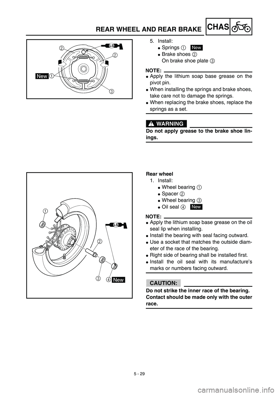
5. Install:
�Springs 1
�Brake shoes 2
On brake shoe plate 3
NOTE:
�Apply the lithium soap base grease on the
pivot pin.
�When installing the springs and brake shoes,
take care not to damage the springs.
�When replacing the brake shoes, replace the
springs as a set.
WARNING
Do not apply grease to the brake shoe lin-
ings.
New
Rear wheel
1. Install:
�Wheel bearing 1
�Spacer 2
�Wheel bearing 3
�Oil seal 4
NOTE:
�Apply the lithium soap base grease on the oil
seal lip when installing.
�Install the bearing with seal facing outward.
�Use a socket that matches the outside diam-
eter of the race of the bearing.
�Right side of bearing shall be installed first.
�Install the oil seal with its manufacture’s
marks or numbers facing outward.
CAUTION:
Do not strike the inner race of the bearing.
Contact should be made only with the outer
race.
New
Page 424 of 510
5 - 30
CHASREAR WHEEL AND REAR BRAKE
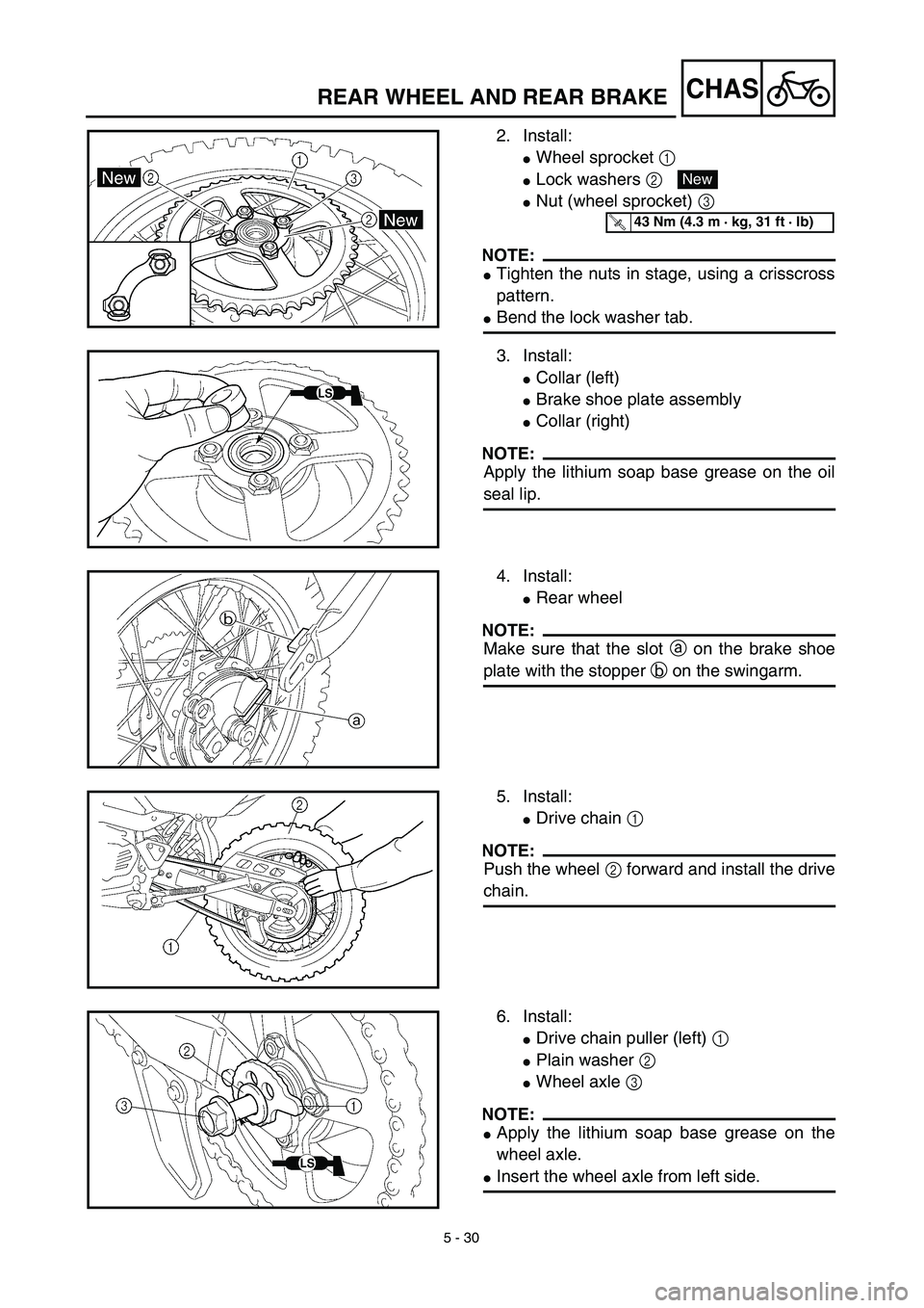
2. Install:
�Wheel sprocket 1
�Lock washers 2
�Nut (wheel sprocket) 3
NOTE:
�Tighten the nuts in stage, using a crisscross
pattern.
�Bend the lock washer tab.
New
T R..43 Nm (4.3 m · kg, 31 ft · lb)
3. Install:
�Collar (left)
�Brake shoe plate assembly
�Collar (right)
NOTE:
Apply the lithium soap base grease on the oil
seal lip.
4. Install:
�Rear wheel
NOTE:
Make sure that the slot a on the brake shoe
plate with the stopper b on the swingarm.
5. Install:
�Drive chain 1
NOTE:
Push the wheel 2 forward and install the drive
chain.
6. Install:
�Drive chain puller (left) 1
�Plain washer 2
�Wheel axle 3
NOTE:
�Apply the lithium soap base grease on the
wheel axle.
�Insert the wheel axle from left side.
Page 430 of 510
5 - 33
CHASFRONT FORK
EC558000
FRONT FORK DISASSEMBLY
Extent of removal:1 Oil seal removal2 Damper rod removal
Extent of removal Order Part name Q’ty Remarks
FRONT FORK DISASSEMBLY
1Dust boot 1
2Cap bolt 1 Refer to “REMOVAL POINTS”.
3Spacer 1
4Washer 1
5Fork spring 1 Drain the fork oil.
6Dust seal 1
Use special tool.
Refer to “REMOVAL POINTS”. 7Stopper ring 1
8Bolt (damper rod) 1
9Damper rod 1
0Inner tube 1
AOil flow stopper 1
BPiston metal 1
COil seal 1
DOuter tube
1
2
1
Page 432 of 510
 5 - 34
CHASFRONT FORK
HANDLING NOTE
NOTE:
The front fork requires careful attention. So it is
recommended that the front fork be main-
tained at the dealers.
CAUTION:
To prevent an accidental explosio")
5 - 34
CHASFRONT FORK
HANDLING NOTE
NOTE:
The front fork requires careful attention. So it is
recommended that the front fork be main-
tained at the dealers.
CAUTION:
To prevent an accidental explosion of air,
the following instructions should be
observed:
The front fork with a built-in piston rod has
a very sophisticated internal construction
and is particularly sensitive to foreign
material.
Use enough care not to allow any foreign
material to come in when the oil is replaced
or when the front fork is disassembled and
reassembled.
EC553000
REMOVAL POINTS
Cap bolt
1. Remove:
�Cap bolt 1
From the inner tube.
NOTE:
Before removing the front fork from the
machine, loosen the cap bolt.
Inner tube
1. Remove:
�Dust seal 1
�Stopper ring 2
Using slotted-head screwdriver.
CAUTION:
Take care not to scratch the inner tube.
2. Remove:
�Bolt (damper rod)
�Damper rod
�Inner tube
�Oil flow stopper
�Piston metal
NOTE:
Use the damper rod holder 1 and the T-han-
dle 2 to lock the damper rod.
 5 - 33
CHASFRONT FORK
EC558000
FRONT FORK DISASSEMBLY
Extent of removal:1 Oil seal removal2 Damper rod removal
Extent of removal Order Part name Q’ty Remarks
FRONT FORK DISASSEMBLY
1Dust boot 1
2Cap")