Page 434 of 510
5 - 35
CHASFRONT FORK
Damper rod holder:
YM-1300/90890-01294
T-handle:
YM-1326/90890-01326
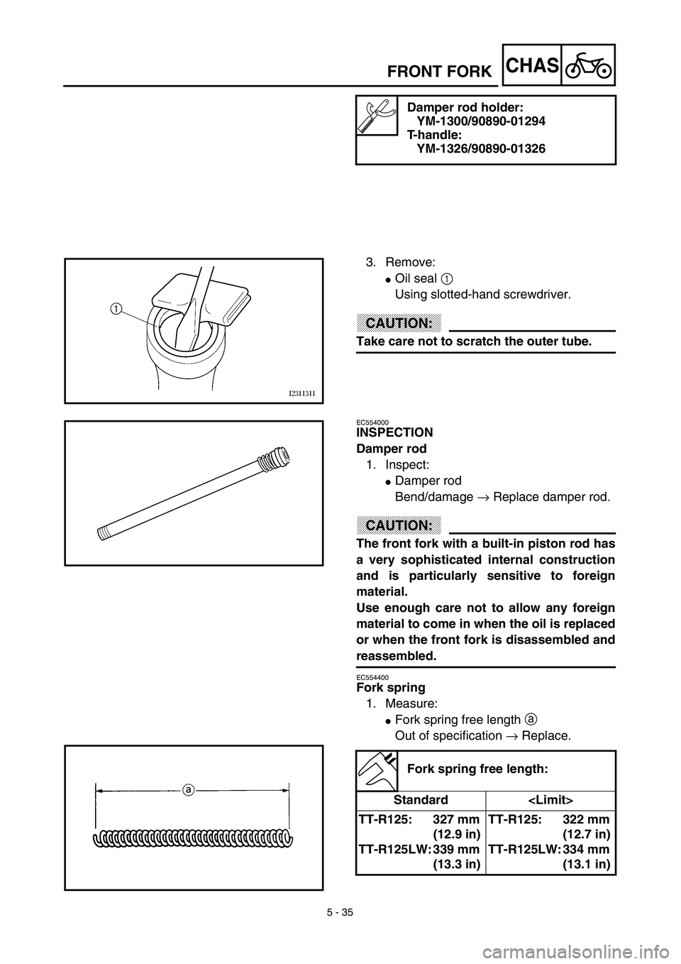
3. Remove:
�Oil seal 1
Using slotted-hand screwdriver.
CAUTION:
Take care not to scratch the outer tube.
EC554000
INSPECTION
Damper rod
1. Inspect:
�Damper rod
Bend/damage → Replace damper rod.
CAUTION:
The front fork with a built-in piston rod has
a very sophisticated internal construction
and is particularly sensitive to foreign
material.
Use enough care not to allow any foreign
material to come in when the oil is replaced
or when the front fork is disassembled and
reassembled.
EC554400
Fork spring
1. Measure:
�Fork spring free length a
Out of specification → Replace.
Fork spring free length:
Standard
TT-R125: 327 mm
(12.9 in)
TT-R125LW: 339 mm
(13.3 in)TT-R125: 322 mm
(12.7 in)
TT-R125LW: 334 mm
(13.1 in)
Page 436 of 510
5 - 36
CHASFRONT FORK
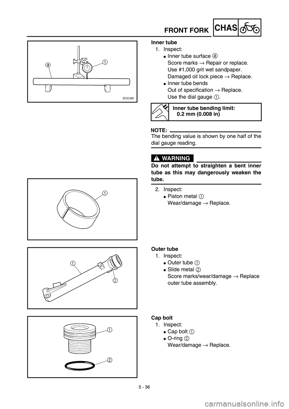
Inner tube
1. Inspect:
�Inner tube surface a
Score marks → Repair or replace.
Use #1,000 grit wet sandpaper.
Damaged oil lock piece → Replace.
�Inner tube bends
Out of specification → Replace.
Use the dial gauge 1.
NOTE:
The bending value is shown by one half of the
dial gauge reading.
WARNING
Do not attempt to straighten a bent inner
tube as this may dangerously weaken the
tube.
2. Inspect:
�Piston metal 1
Wear/damage → Replace.
Inner tube bending limit:
0.2 mm (0.008 in)
Outer tube
1. Inspect:
�Outer tube 1
�Slide metal 2
Score marks/wear/damage → Replace
outer tube assembly.
Cap bolt
1. Inspect:
�Cap bolt 1
�O-ring 2
Wear/damage → Replace.
Page 438 of 510
5 - 37
CHAS
EC555000
ASSEMBLY AND INSTALLATION
Front fork assembly
1. Wash the all parts in a clean solvent.
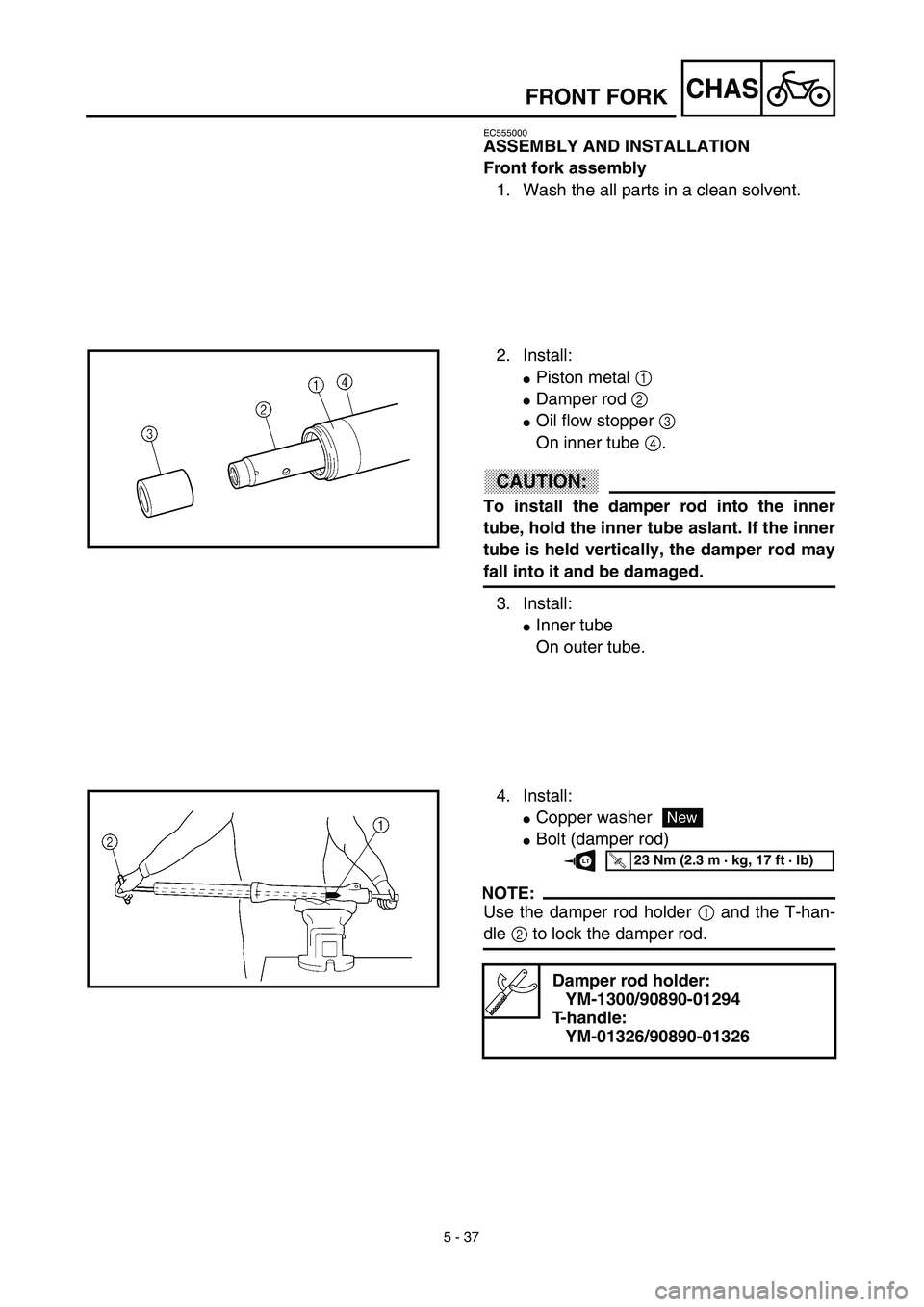
2. Install:
�Piston metal 1
�Damper rod 2
�Oil flow stopper 3
On inner tube 4.
CAUTION:
To install the damper rod into the inner
tube, hold the inner tube aslant. If the inner
tube is held vertically, the damper rod may
fall into it and be damaged.
3. Install:
�Inner tube
On outer tube.
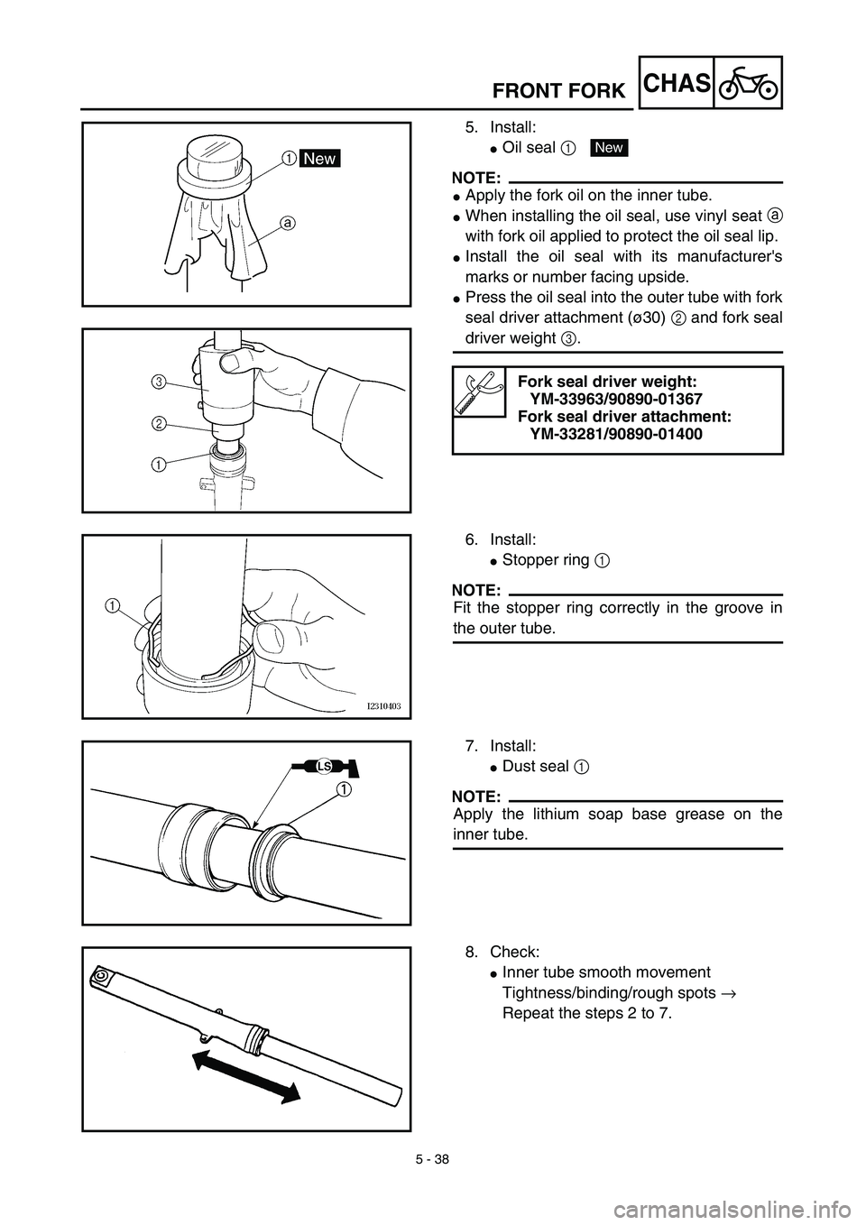
4. Install:
�Copper washer
�Bolt (damper rod)
NOTE:
Use the damper rod holder 1 and the T-han-
dle 2 to lock the damper rod.
Damper rod holder:
YM-1300/90890-01294
T-handle:
YM-01326/90890-01326
New
T R..23 Nm (2.3 m · kg, 17 ft · lb)LT
FRONT FORK
Page 440 of 510
5 - 38
CHASFRONT FORK
5. Install:
�Oil seal 1
NOTE:
�Apply the fork oil on the inner tube.
�When installing the oil seal, use vinyl seat a
with fork oil applied to protect the oil seal lip.
�Install the oil seal with its manufacturer's
marks or number facing upside.
�Press the oil seal into the outer tube with fork
seal driver attachment (ø30) 2 and fork seal
driver weight 3.
Fork seal driver weight:
YM-33963/90890-01367
Fork seal driver attachment:
YM-33281/90890-01400
New
6. Install:
�Stopper ring 1
NOTE:
Fit the stopper ring correctly in the groove in
the outer tube.
7. Install:
�Dust seal 1
NOTE:
Apply the lithium soap base grease on the
inner tube.
8. Check:
�Inner tube smooth movement
Tightness/binding/rough spots →
Repeat the steps 2 to 7.
Page 441 of 510
 5 - 38
CHAS
5. Montieren:
�Dichtring 1
HINWEIS:
�Gabelöl auf das Standrohr auftragen.
�Bei der Montage des Dichtrings mit Gabelöl
bestrichene Vinyl-Montagehilfe a verwenden,
um Dichtlippe des Dicht")
5 - 38
CHAS
5. Montieren:
�Dichtring 1
HINWEIS:
�Gabelöl auf das Standrohr auftragen.
�Bei der Montage des Dichtrings mit Gabelöl
bestrichene Vinyl-Montagehilfe a verwenden,
um Dichtlippe des Dichtrings zu schützen.
�Dichtringe so einbauen, daß die Hersteller-
beschriftung oder Teilenummer sichtbar
bleibt.
�Dichtring mit Gabeldichtring-Treibhülse
(ø30) 2 und Gabeldichtring-Treiber 3 im
Tauchrohr montieren.
Gabeldichtring-Treiber
YM-33963/90890-01367
Gabeldichtring-Führungshülse
YM-33281/90890-01400
New
6. Montieren:
�Sicherungsring 1
HINWEIS:
Sicherungsring richtig in die Nut im Tauchrohr
einpassen.
7. Montieren:
�Staubschutz 1
HINWEIS:
Lithiumfett auf Standrohr auftragen.
8. Prüfen:
�Leichtgängigkeit des Standrohrs
Schwergängigkeit/Klemmen/Rauhig-
keit → Schritte 2 bis 7 wiederholen.
FOURCHE AVANT
TELESKOPGABEL
5. Installer:
�Bague d’étanchéité 1
N.B.:
�Enduire le tube plongeur d’huile de fourche.
�Pour installer la bague d’étanchéité sans abîmer
les lèvres de la bague d’étanchéité, se servir d’une
toile en plastique a enduite d’huile de fourche.
�Monter la bague d’étanchéité en veillant à ce que
son côté porteur de la marque ou du repère du
fabricant soit dirigé vers le haut.
�Forcer la bague d’étanchéité dans le fourreau à
l’aide de l’accessoire de l’outil de montage de
joint de fourche (ø30) 2 et du poids de montage
de joint de fourche 3.
Poids de montage de joint de fourche:
YM-33963/90890-01367
Accessoire de l’outil de montage de
joint de fourche:
YM-33281/90890-01400
New
6. Installer:
�Clip de maintien 1
N.B.:
Loger correctement le clip de maintien dans la rai-
nure du fourreau.
7. Installer:
Joint antipoussière 1
N.B.:
Enduire le tube plongeur de graisse à base de savon
au lithium.
8. Contrôler:
�Coulissement régulier du tube plongeur
Étroitesse/points durs/surface inégale →
Recommencer les étapes 2 à 7.
Page 442 of 510
5 - 39
CHASFRONT FORK
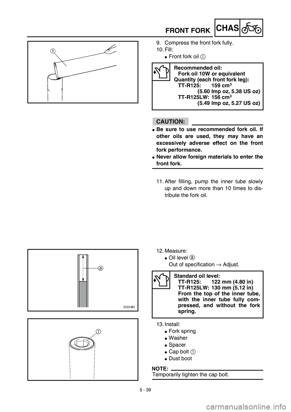
9. Compress the front fork fully.
10. Fill:
�Front fork oil 1
CAUTION:
�Be sure to use recommended fork oil. If
other oils are used, they may have an
excessively adverse effect on the front
fork performance.
�Never allow foreign materials to enter the
front fork.
Recommended oil:
Fork oil 10W or equivalent
Quantity (each front fork leg):
TT-R125: 159 cm
3
(5.60 Imp oz, 5.38 US oz)
TT-R125LW: 156 cm
3
(5.49 lmp oz, 5.27 US oz)
11. After filling, pump the inner tube slowly
up and down more than 10 times to dis-
tribute the fork oil.
12. Measure:
�Oil level a
Out of specification → Adjust.
13. Install:
�Fork spring
�Washer
�Spacer
�Cap bolt 1
�Dust boot
NOTE:
Temporarily tighten the cap bolt.
Standard oil level:
TT-R125: 122 mm (4.80 in)
TT-R125LW: 130 mm (5.12 in)
From the top of the inner tube,
with the inner tube fully com-
pressed, and without the fork
spring.
Page 456 of 510
5 - 46
CHAS
ASSEMBLY AND INSTALLATION
Throttle grip assembly
1. Install:
�Collar 1
�Handlebar grip (right) 2
Apply the adhesive on the tube guide
3.
NOTE:
Before applying the adhesive, wipe off grease
or oil on the tube guide surface a with a lac-
quer thinner.
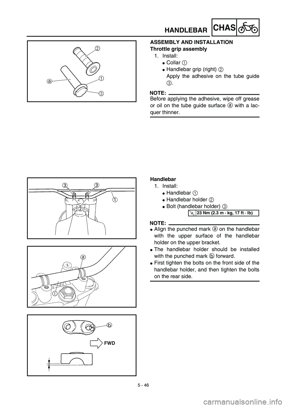
Handlebar
1. Install:
�Handlebar 1
�Handlebar holder 2
�Bolt (handlebar holder) 3
NOTE:
�Align the punched mark a on the handlebar
with the upper surface of the handlebar
holder on the upper bracket.
�The handlebar holder should be installed
with the punched mark b forward.
�First tighten the bolts on the front side of the
handlebar holder, and then tighten the bolts
on the rear side.
T R..23 Nm (2.3 m · kg, 17 ft · lb)
HANDLEBAR
Page 458 of 510
5 - 47
CHAS
2. Install:
�Handlebar grip (left) 1
Apply the adhesive to the handlebar 2.
NOTE:
Before applying the adhesive, wipe off grease
or oil on the handlebar surface a with a lac-
quer thinner.
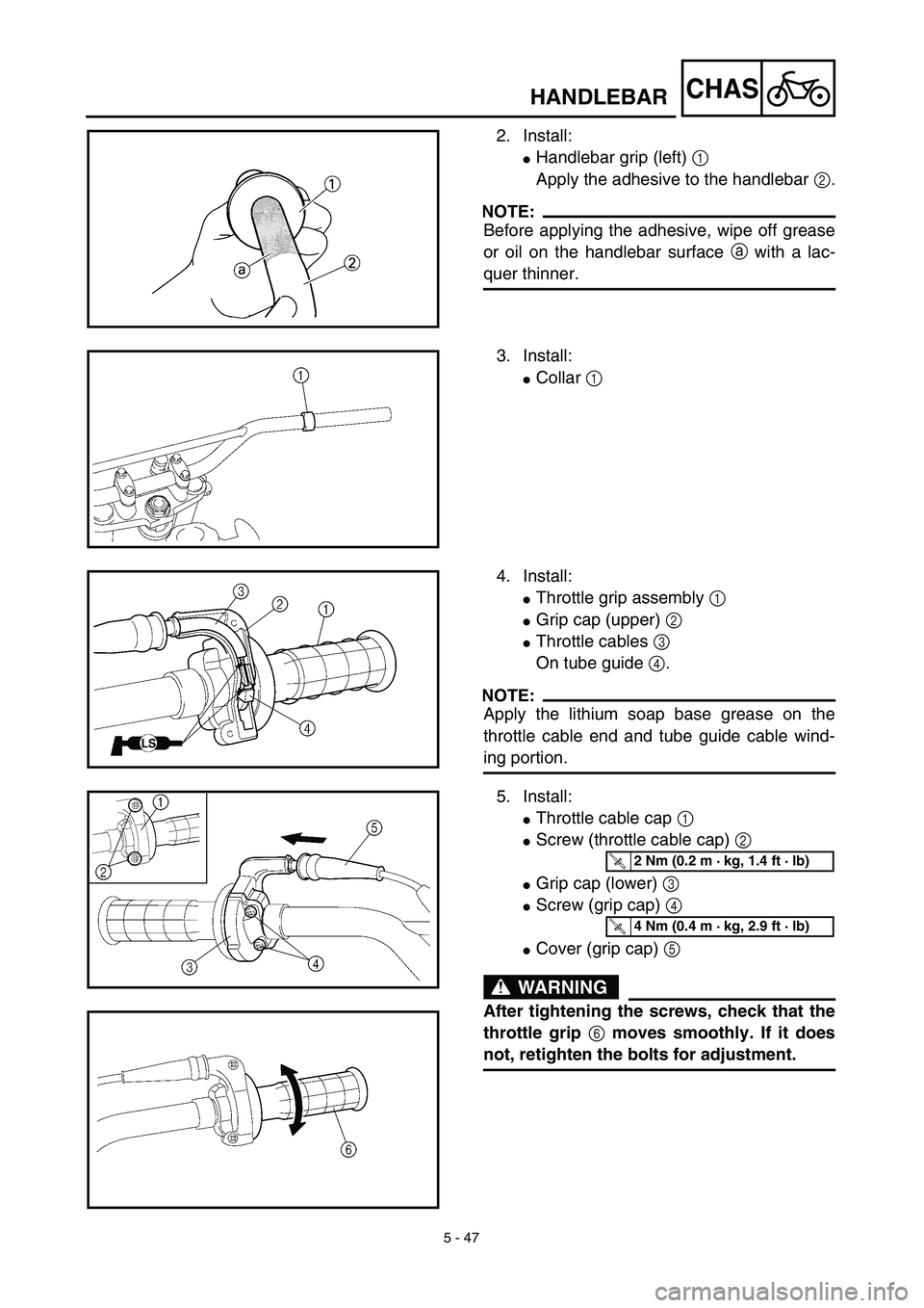
3. Install:
�Collar 1
4. Install:
�Throttle grip assembly 1
�Grip cap (upper) 2
�Throttle cables 3
On tube guide 4.
NOTE:
Apply the lithium soap base grease on the
throttle cable end and tube guide cable wind-
ing portion.
5. Install:
�Throttle cable cap 1
�Screw (throttle cable cap) 2
�Grip cap (lower) 3
�Screw (grip cap) 4
�Cover (grip cap) 5
WARNING
After tightening the screws, check that the
throttle grip 6 moves smoothly. If it does
not, retighten the bolts for adjustment.
T R..2 Nm (0.2 m · kg, 1.4 ft · lb)
T R..4 Nm (0.4 m · kg, 2.9 ft · lb)
HANDLEBAR