Page 376 of 510
5 - 6
CHASFRONT WHEEL AND FRONT BRAKE (TT-R125)
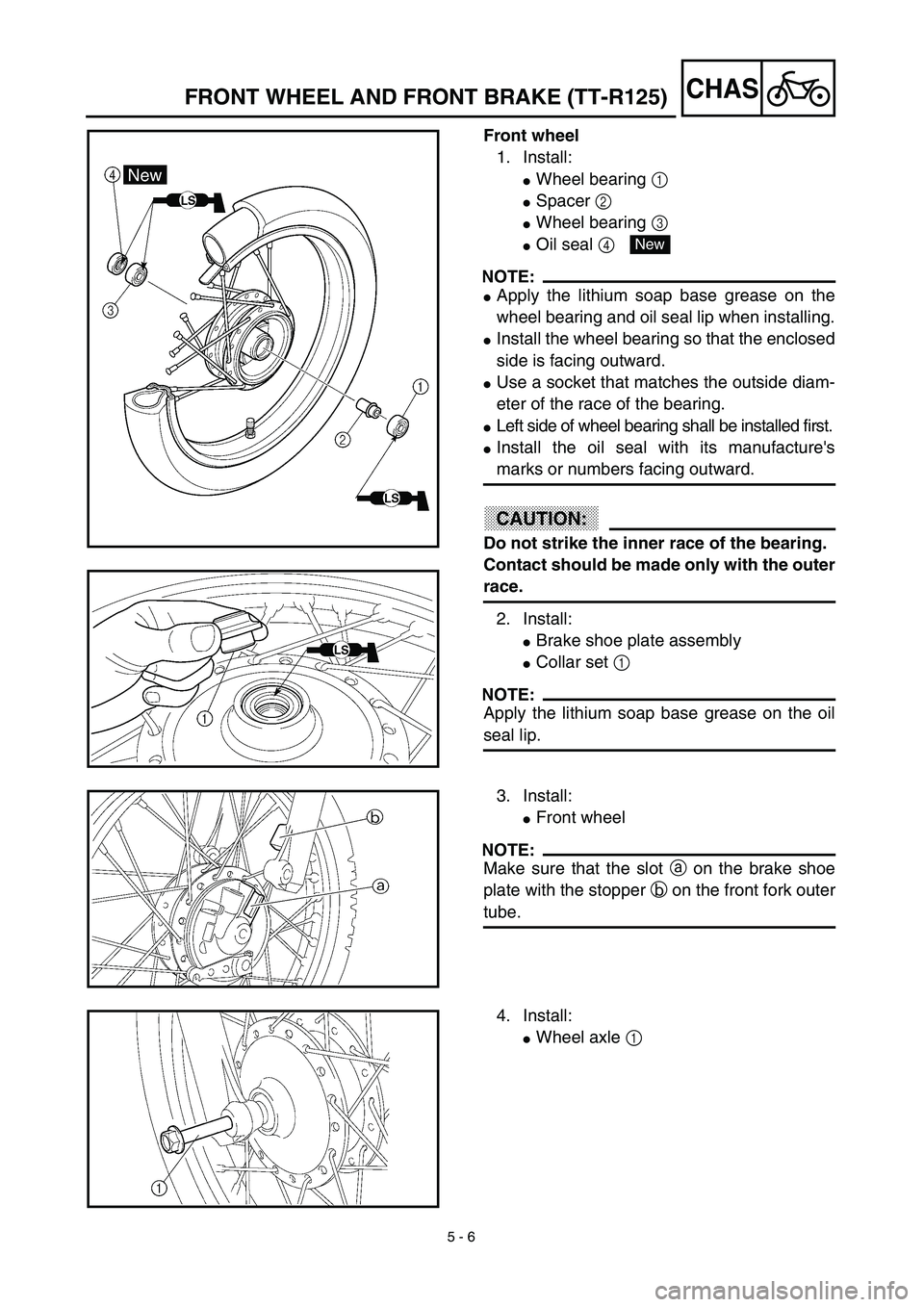
Front wheel
1. Install:
�Wheel bearing 1
�Spacer 2
�Wheel bearing 3
�Oil seal 4
NOTE:
�Apply the lithium soap base grease on the
wheel bearing and oil seal lip when installing.
�Install the wheel bearing so that the enclosed
side is facing outward.
�Use a socket that matches the outside diam-
eter of the race of the bearing.
�Left side of wheel bearing shall be installed first.
�Install the oil seal with its manufacture's
marks or numbers facing outward.
CAUTION:
Do not strike the inner race of the bearing.
Contact should be made only with the outer
race.
2. Install:
�Brake shoe plate assembly
�Collar set 1
NOTE:
Apply the lithium soap base grease on the oil
seal lip.
New
3. Install:
�Front wheel
NOTE:
Make sure that the slot a on the brake shoe
plate with the stopper b on the front fork outer
tube.
4. Install:
�Wheel axle 1
Page 380 of 510
5 - 8
CHAS
FRONT WHEEL (TT-R125LW)
Extent of removal:1 Front wheel removal2 Wheel bearing removal
3 Brake disc removal
Extent of removal Order Part name Q’ty Remarks
Preparation for removalFRONT WHEEL REMOVAL
Hold the machine by placing the
suitable stand under the engine.
WARNING
Support the machine securely so there is nodanger of it falling over.
1 Axle nut 1
2 Washer 1
3 Wheel axle 1
4 Front wheel 1
5 Collar 2
6 Oil seal 2
7 Wheel bearing 2 Refer to “REMOVAL POINTS”.
8 Spacer 1
9Brake disk
1
2
31
3
FRONT WHEEL (TT-R125LW)
Page 382 of 510
5 - 9
CHASFRONT WHEEL (TT-R125LW)
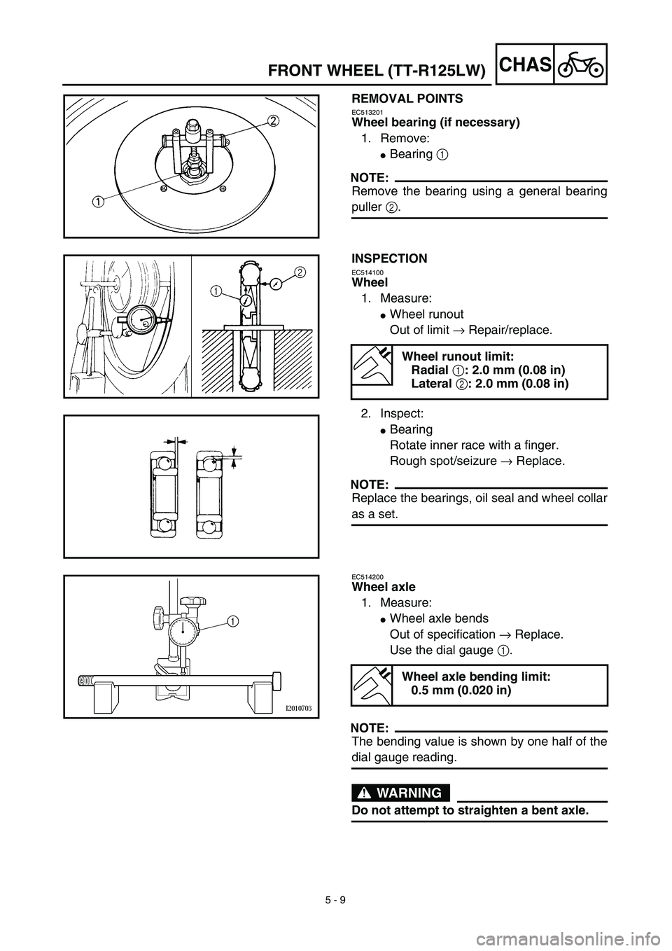
REMOVAL POINTS
EC513201
Wheel bearing (if necessary)
1. Remove:
�Bearing 1
NOTE:
Remove the bearing using a general bearing
puller 2.
INSPECTION
EC514100
Wheel
1. Measure:
�Wheel runout
Out of limit → Repair/replace.
2. Inspect:
�Bearing
Rotate inner race with a finger.
Rough spot/seizure → Replace.
NOTE:
Replace the bearings, oil seal and wheel collar
as a set.
Wheel runout limit:
Radial 1: 2.0 mm (0.08 in)
Lateral 2: 2.0 mm (0.08 in)
EC514200
Wheel axle
1. Measure:
�Wheel axle bends
Out of specification → Replace.
Use the dial gauge 1.
NOTE:
The bending value is shown by one half of the
dial gauge reading.
WARNING
Do not attempt to straighten a bent axle.
Wheel axle bending limit:
0.5 mm (0.020 in)
Page 383 of 510
 5 - 9
CHAS
ROUE AVANT (TT-R125LW)
VORDERRAD (TT-R125LW)
DEMONTAGEPUNKTE
Radlager (falls erforderlich)
1. Demontieren:
�Lager 1
HINWEIS:
Lager mit einem herkömmlichen Lageraustrei-
ber 2 demontieren.")
5 - 9
CHAS
ROUE AVANT (TT-R125LW)
VORDERRAD (TT-R125LW)
DEMONTAGEPUNKTE
Radlager (falls erforderlich)
1. Demontieren:
�Lager 1
HINWEIS:
Lager mit einem herkömmlichen Lageraustrei-
ber 2 demontieren.
PRÜFEN
Rad
1. Messen:
�Max. Schlag
Unvorschriftsmäßig → Reparieren/
erneuern.
2. Prüfen:
�Lager
Inneren Lagerlaufring mit einem Finger
drehen.
Rauheit/Lager fest → Erneuern.
HINWEIS:
Lager, Dichtring und Paßhülse satzweise
erneuern.
Maximal zulässiger Schlag
Max. Höhenschlag 1: 2,0 mm
Max. Seitenschlag 2: 2,0 mm
Radachse
1. Messen:
�Radachsenbiegung
Unvorschriftsmäßig → Erneuern.
Meßuhr 1 verwenden.
HINWEIS:
Der Verzug ergibt sich aus der Hälfte des von
der Meßuhr angezeigten Wertes.
WARNUNG
Niemals versuchen, eine verbogene Achse
zu richten.
Maximal zulässige Achsbiegung
0,5 mm
PIÈCES À DÉPOSER
Roulement de roue (si nécessaire)
1. Déposer:
�Roulement 1
N.B.:
Déposer le roulement à l’aide d’un extracteur de
roulements universel 2.
CONTRÔLE
Roue
1. Mesurer:
�Déformation de la roue
Hors spécifications → Réparer ou rempla-
cer.
2. Examiner:
�Roulement
Faire tourner la cage interne à l’aide d’un
doigt.
Dureté/grippage → Remplacer.
N.B.:
Remplacer à la fois les roulements, la bague d’étan-
chéité et l’entretoise épaulée.
Limite de voile de roue:
Radial 1: 2,0 mm (0,08 in)
Latéral 2: 2,0 mm (0,08 in)
Axe de roue
1. Mesurer:
�Déformations de l’axe de roue
Hors spécifications → Remplacer.
Utiliser un comparateur à cadran 1.
N.B.:
Pour obtenir la déformation, il faut diviser en deux
la valeur affichée sur le comparateur à cadran.
AVERTISSEMENT
Ne pas tenter de redresser un axe déformé.
Limite de déformation d’axe de roue:
0,5 mm (0,020 in)
Page 384 of 510
5 - 10
CHASFRONT WHEEL (TT-R125LW)
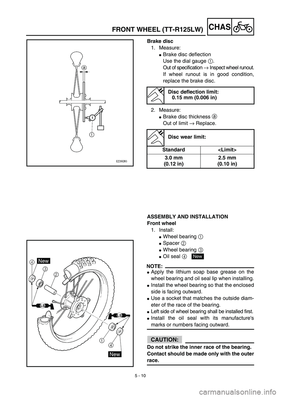
Brake disc
1. Measure:
�Brake disc deflection
Use the dial gauge 1.
Out of specification → Inspect wheel runout.
If wheel runout is in good condition,
replace the brake disc.
2. Measure:
�Brake disc thickness a
Out of limit → Replace.
Disc deflection limit:
0.15 mm (0.006 in)
Disc wear limit:
Standard
3.0 mm
(0.12 in)2.5 mm
(0.10 in)
ASSEMBLY AND INSTALLATION
Front wheel
1. Install:
�Wheel bearing 1
�Spacer 2
�Wheel bearing 3
�Oil seal 4
NOTE:
�Apply the lithium soap base grease on the
wheel bearing and oil seal lip when installing.
�Install the wheel bearing so that the enclosed
side is facing outward.
�Use a socket that matches the outside diam-
eter of the race of the bearing.
�Left side of wheel bearing shall be installed first.
�Install the oil seal with its manufacture's
marks or numbers facing outward.
CAUTION:
Do not strike the inner race of the bearing.
Contact should be made only with the outer
race.
New
Page 386 of 510
5 - 11
CHASFRONT WHEEL (TT-R125LW)
2. Install:
�Brake disc 1
�Bolt (brake disc) 2
NOTE:
Tighten the bolts in stage, using a crisscross
pattern.
T R..12 Nm (1.2 m · kg, 8.7 ft · lb)LT
3. Install:
�Collar 1
NOTE:
�Apply the lithium soap base grease on the oil
seal lips.
�Install the longer collar on the brake disc 2
side.
4. Install:
�Front wheel
NOTE:
Install the brake disc 1 between the brake
pads 2 correctly.
5. Install:
�Wheel axle 1
6. Install:
�Washer 1
�Axle nut 2
T R..45 Nm (4.5 m · kg, 32 ft · lb)
Page 408 of 510
5 - 22
CHAS
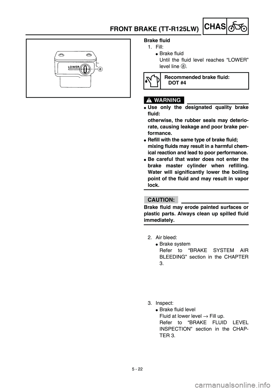
Brake fluid
1. Fill:
�Brake fluid
Until the fluid level reaches “LOWER”
level line a.
WARNING
�Use only the designated quality brake
fluid:
otherwise, the rubber seals may deterio-
rate, causing leakage and poor brake per-
formance.
�Refill with the same type of brake fluid;
mixing fluids may result in a harmful chem-
ical reaction and lead to poor performance.
�Be careful that water does not enter the
brake master cylinder when refilling.
Water will significantly lower the boiling
point of the fluid and may result in vapor
lock.
CAUTION:
Brake fluid may erode painted surfaces or
plastic parts. Always clean up spilled fluid
immediately.
Recommended brake fluid:
DOT #4
2. Air bleed:
�Brake system
Refer to “BRAKE SYSTEM AIR
BLEEDING” section in the CHAPTER
3.
3. Inspect:
�Brake fluid level
Fluid at lower level → Fill up.
Refer to “BRAKE FLUID LEVEL
INSPECTION” section in the CHAP-
TER 3.
FRONT BRAKE (TT-R125LW)
Page 414 of 510
5 - 25
CHAS
Extent of removal Order Part name Q’ty Remarks
11 Nut (wheel sprocket) 4
12 Wheel sprocket 1
13 Oil seal 1
14 Wheel bearing 2 Refer to “REMOVAL POINTS”.
15 Spacer 1
16 Brake shoe 2
17 Spring 2
18 Brake camshaft lever 1
19 Wear indicator plate 1
20 Brake camshaft 1
21 Brake shoe plate 1
3
2
REAR WHEEL AND REAR BRAKE
 5 - 8
CHAS
FRONT WHEEL (TT-R125LW)
Extent of removal:1 Front wheel removal2 Wheel bearing removal
3 Brake disc removal
Extent of removal Order Part name Q’ty Remarks
Preparation for removalFRONT WHE")

 5 - 25
CHAS
Extent of removal Order Part name Q’ty Remarks
11 Nut (wheel sprocket) 4
12 Wheel sprocket 1
13 Oil seal 1
14 Wheel bearing 2 Refer to “REMOVAL POINTS”.
15 Spacer 1
16 Brake shoe 2
1")