Page 170 of 510
 3 - 10
INSP
ADJOIL PRESSURE INSPECTION/PILOT AIR SCREW
ADJUSTMENT/ENGINE IDLING SPEED ADJUSTMENT
OIL PRESSURE INSPECTION
1. Check:
�Oil pressure
Checking steps:
�Slightly loosen the oil pressure check")
3 - 10
INSP
ADJOIL PRESSURE INSPECTION/PILOT AIR SCREW
ADJUSTMENT/ENGINE IDLING SPEED ADJUSTMENT
OIL PRESSURE INSPECTION
1. Check:
�Oil pressure
Checking steps:
�Slightly loosen the oil pressure check bolt
1.
�Start the engine and keep it idling until oil
starts to seep from the oil pressure check
bolt. If no oil comes out after one minute,
turn the engine off so it will not seize.
�Check oil passages and oil pump for dam-
age or leakage.
�Start the engine after solving the prob-
lem(s) and recheck the oil pressure.
�Tighten the oil pressure check bolt.
T R..
Oil pressure check bolt:
7 Nm (0.7 m • kg, 5.1 ft • lb)
PILOT AIR SCREW ADJUSTMENT
1. Adjust:
�Pilot air screw 1
Adjustment steps:
NOTE:
To optimize the fuel flow at a smaller throttle
opening, each machine’s pilot air screw has
been individually set at the factory. Before
adjusting the pilot air screw, turn it in fully
and count the number of turns. Record this
number as the factory-set number of turns
out.
�Screw in the pilot air screw until it is lightly
seated.
�Back out by the specified number of turns.
Pilot air screw:
2-1/2 ~ 3-1/2 turns out (example)
ENGINE IDLING SPEED ADJUSTMENT
1. Start the engine and thoroughly warm it
up.
2. Attach:
�Inductive tachometer
To spark plug lead.
3. Adjust:
�Engine idling speed
Page 179 of 510
 INSP
ADJNETTOYAGE DU PARE-ÉTINCELLES (pour les USA)
FUNKENLÖSCHER REINIGEN (Nur USA)
FUNKENLÖSCHER REINIGEN (Nur USA)
WARNUNG
�Sicherstellen, daß Krümmer und Schall-
dämpfer abgekühlt sind, bev")
INSP
ADJNETTOYAGE DU PARE-ÉTINCELLES (pour les USA)
FUNKENLÖSCHER REINIGEN (Nur USA)
FUNKENLÖSCHER REINIGEN (Nur USA)
WARNUNG
�Sicherstellen, daß Krümmer und Schall-
dämpfer abgekühlt sind, bevor der Fun-
kenlöscher gereinigt wird.
�Motor beim Reinigen der Auspuffanlage
nicht starten.
1. Demontieren:
�Schraube (Funkenlöscher) 1
2. Demontieren:
�Funkenlöscher 1
Funkenlöscher aus dem Schalldämp-
fer herausziehen.
3. Reinigen:
�Funkenlöscher
Funkenlöscher vorsichtig ausklopfen
und anschließend mit einer Drahtbürste
alle Kohleablagerungen beseitigen.
4. Montieren:
�Funkenlöscher
Funkenlöscher in den Schalldämpfer
hineinschieben und auf die Bohrungen
für die Schrauben ausrichten.
�Schraube (Funkenlöscher)
T R..10 Nm (1,0 m · kg)
NETTOYAGE DU PARE-ÉTINCELLES
(pour les USA)
AVERTISSEMENT
�S’assurer que le tuyau et pot d’échappement
sont froids avant d’effectuer le nettoyage du
pare-étincelles.
�Ne pas mettre le moteur en marche pendant le
nettoyage du système d’échappement.
1. Déposer:
�Boulon (pare-étincelles) 1
2. Déposer:
�Pare-étincelles 1
Extraire le pare-étincelles du pot d’échap-
pement.
3. Nettoyer:
�Pare-étincelles
Tapoter légèrement le pare-étincelles, puis
nettoyer les dépôts de calamine à l’aide
d’une brosse à poils métalliques.
4. Installer:
�Pare-étincelles
Loger le pare-étincelles dans le pot
d’échappement et aligner les orifices de
boulon.
�Boulon (pare-étincelles)
T R..10 Nm (1,0 m · kg, 7,2 ft · lb)
3 - 14
Page 192 of 510
3 - 21
INSP
ADJ
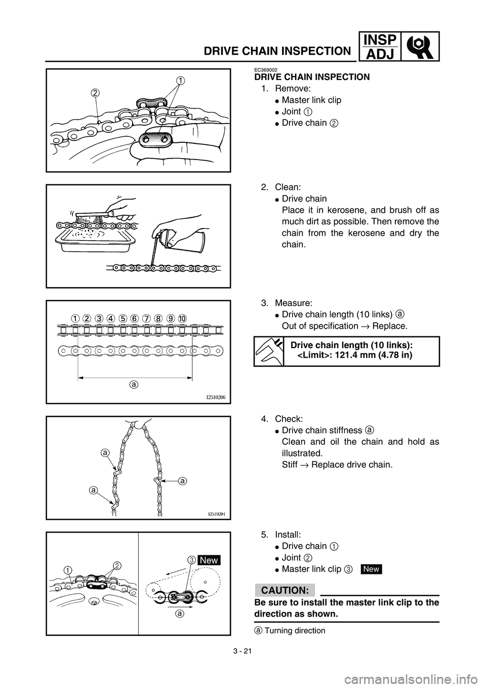
DRIVE CHAIN INSPECTION
EC369002
DRIVE CHAIN INSPECTION
1. Remove:
�Master link clip
�Joint 1
�Drive chain 2
2. Clean:
�Drive chain
Place it in kerosene, and brush off as
much dirt as possible. Then remove the
chain from the kerosene and dry the
chain.
3. Measure:
�Drive chain length (10 links) a
Out of specification → Replace.
Drive chain length (10 links):
: 121.4 mm (4.78 in)
4. Check:
�Drive chain stiffness a
Clean and oil the chain and hold as
illustrated.
Stiff → Replace drive chain.
5. Install:
�Drive chain 1
�Joint 2
�Master link clip 3
CAUTION:
Be sure to install the master link clip to the
direction as shown.
aTurning direction
New
Page 194 of 510
 3 - 22
INSP
ADJ
DRIVE CHAIN SLACK ADJUSTMENT
6. Lubricate:
�Drive chain
Drive chain lubricant:
SAE 10W-30 motor oil or suit-
able chain lubricants
DRIVE CHAIN SLACK ADJUSTMENT
1. Elevate the rear whee")
3 - 22
INSP
ADJ
DRIVE CHAIN SLACK ADJUSTMENT
6. Lubricate:
�Drive chain
Drive chain lubricant:
SAE 10W-30 motor oil or suit-
able chain lubricants
DRIVE CHAIN SLACK ADJUSTMENT
1. Elevate the rear wheel by placing the
suitable stand under the engine.
2. Check:
�Drive chain slack a
In the center between the drive axle
and rear wheel axle.
Out of specification → Adjust.
NOTE:
Before checking and/or adjusting, rotate the
rear wheel through several revolutions and
check the slack several times to find the tight-
est point. Check and/or adjust chain slack with
rear wheel in this “tight chain” position.
Drive chain slack:
35 ~ 50 mm (1.4 ~ 2.0 in)
3. Adjust:
�Drive chain slack
Drive chain slack adjustment steps:
�Loosen the axle nut 1.
�Turn both drive chain pullers 2 the same
amount a and adjust them to the stopper
in the same position so that the drive
chain slack is within the specified limits.
CAUTION:
Too small chain slack will overload the
engine and other vital parts; keep the
slack within the specified limits.
�Tighten the axle nut while pushing down
the drive chain.
T R..
Axle nut:
60 Nm (6.0 m • kg, 43 ft • lb)
Page 196 of 510
3 - 23
INSP
ADJ
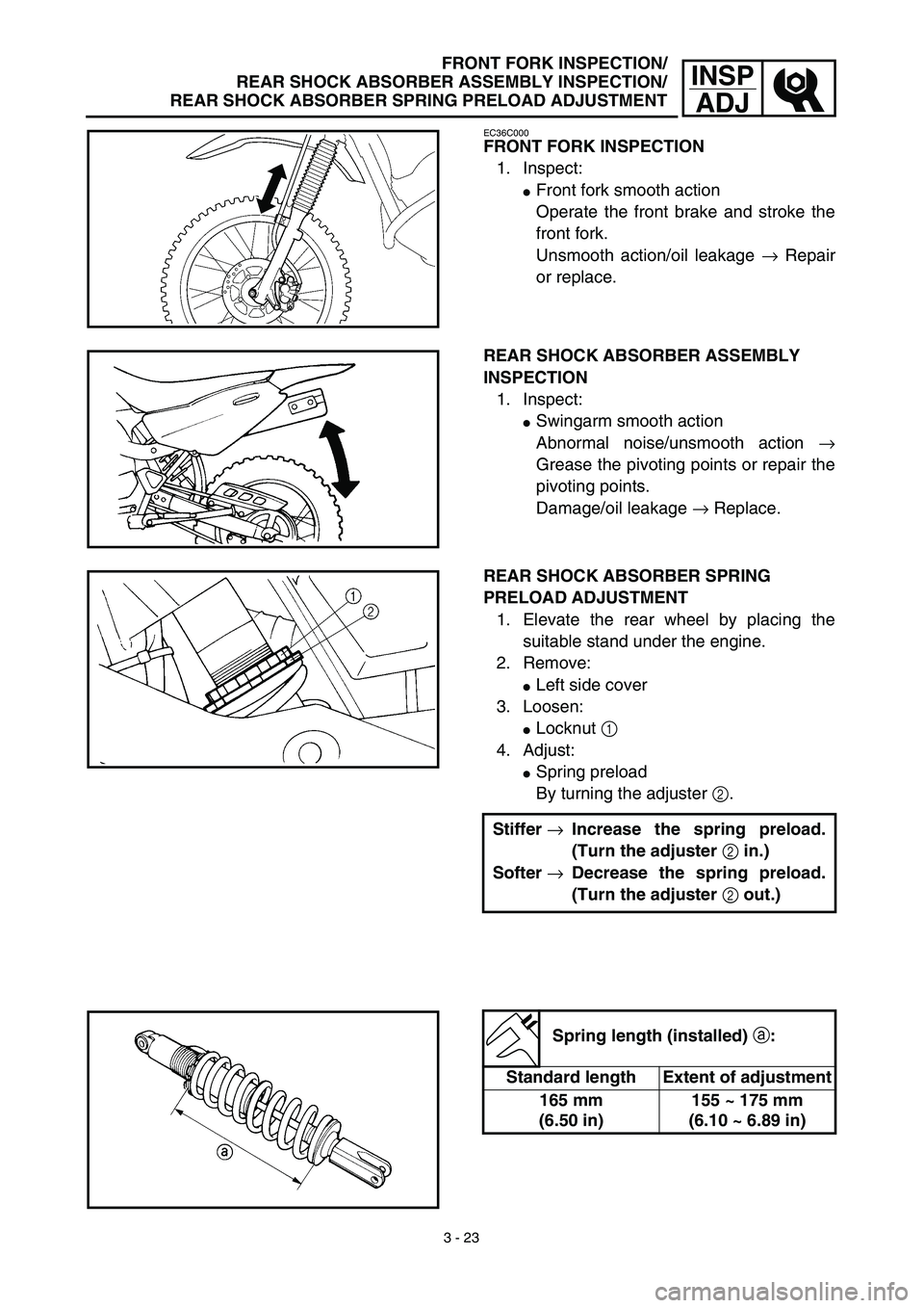
FRONT FORK INSPECTION/
REAR SHOCK ABSORBER ASSEMBLY INSPECTION/
REAR SHOCK ABSORBER SPRING PRELOAD ADJUSTMENT
EC36C000
FRONT FORK INSPECTION
1. Inspect:
�Front fork smooth action
Operate the front brake and stroke the
front fork.
Unsmooth action/oil leakage → Repair
or replace.
REAR SHOCK ABSORBER ASSEMBLY
INSPECTION
1. Inspect:
�Swingarm smooth action
Abnormal noise/unsmooth action →
Grease the pivoting points or repair the
pivoting points.
Damage/oil leakage → Replace.
REAR SHOCK ABSORBER SPRING
PRELOAD ADJUSTMENT
1. Elevate the rear wheel by placing the
suitable stand under the engine.
2. Remove:
�Left side cover
3. Loosen:
�Locknut 1
4. Adjust:
�Spring preload
By turning the adjuster 2.
Stiffer →Increase the spring preload.
(Turn the adjuster 2 in.)
Softer →Decrease the spring preload.
(Turn the adjuster 2 out.)
Spring length (installed) a:
Standard length Extent of adjustment
165 mm
(6.50 in)155 ~ 175 mm
(6.10 ~ 6.89 in)
Page 206 of 510
3 - 28
INSP
ADJ
LUBRICATION
LUBRICATION
To ensure smooth operation of all compo-
nents, lubricate your machine during setup,
after break-in, and after every ride.
1All control cable
2Brake and clutch lever pivots
3Shift pedal pivot
4Footrest pivot
5Throttle-to-handlebar contact
6Drive chain
7Tube guide cable winding portion
8Throttle cable end
9Brake and clutch cable ends
(Clutch cable end only for the TT-R125LW)ÅUse Yamaha cable lube or equivalent on these
areas.
ıUse SAE 10W-30 motor oil or suitable chain
lubricants.
ÇLubricate the following areas with high quality,
lightweight lithium-soap base grease.
AAA
AAB
CC
Page 240 of 510
4 - 16
ENGCYLINDER HEAD
Warpage limit:
0.03 mm (0.0012 in)
�If the warpage is out of specification,
resurface the cylinder head.
�Place #400 ~ 600 grit wet sandpaper on
the surface plate, and re-surface the head
using a figure-eight sanding pattern.
NOTE:
Rotate the cylinder head several times to
avoid removing too much material from one
side.
ASSEMBLY AND INSTALLATION
Cylinder head
1. Install:
�Dowel pin 1
�Gasket 2 New
2. Install:
�Cylinder head
�Copper washer
�Bolt (cylinder head)
NOTE:
�Apply Quick gasket® (YAMAHA Bond
No.1215) on end of the cylinder head bolts
(M6), as shown.
�Apply the engine oil on the contact surfaces of
the bolts (cylinder head) and copper washers.
�Follow the numerical order shown in the illus-
tration. Tighten the bolts in two stages.
Quick gasket®:
ACC-QUICK-GS-KT
YAMAHA Bond No.1215:
90890-85505
T R..M8 22 Nm (2.2 m · kg, 16 ft · lb)
M6 10 Nm (1.0 m · kg, 7.2 ft · lb)
Page 246 of 510
4 - 19
ENGCYLINDER HEAD
9. Check:
�Valve clearance
Out of specification → Adjust.
Refer to “VALVE CLEARANCE
INSPECTION AND ADJUSTMENT”
section in the CHAPTER 3.
10. Apply:
�Engine oil
On camshaft.
11. Install:
�Tappet cover 1
�Cylinder head side cover 2
T R..18 Nm (1.8 m · kg, 13 ft · lb)
T R..10 Nm (1.0 m · kg, 7.2 ft · lb)
12. Install:
�Timing mark accessing screw 1
�Crankshaft end accessing screw 2
T R..7 Nm (0.7 m · kg, 5.1 ft · lb)
T R..7 Nm (0.7 m · kg, 5.1 ft · lb)
13. Install:
�Spark plug
�Engine bracket
T R..13 Nm (1.3 m · kg, 9.4 ft · lb)
T R..40 Nm (4.0 m · kg, 29 ft · lb)
 3 - 28
INSP
ADJ
LUBRICATION
LUBRICATION
To ensure smooth operation of all compo-
nents, lubricate your machine during setup,
after break-in, and after every ride.
1All control cable
2Brake and clutch")

