Page 398 of 510
 5 - 17
CHASFRONT BRAKE (TT-R125LW)
ASSEMBLY AND INSTALLATION
WARNING
�All internal parts should be cleaned in
new brake fluid only.
�Internal parts should be lubricated with
brake fluid when installed")
5 - 17
CHASFRONT BRAKE (TT-R125LW)
ASSEMBLY AND INSTALLATION
WARNING
�All internal parts should be cleaned in
new brake fluid only.
�Internal parts should be lubricated with
brake fluid when installed.
�Replace the brake caliper piston seals
and brake caliper dust seals whenever a
brake caliper is disassembled.
Brake caliper piston
1. Clean:
�Brake caliper
�Brake caliper piston seal
�Brake caliper dust seal
�Brake caliper piston
Clean them with brake fluid.
2. Install:
�Brake caliper piston seal 1
�Brake caliper dust seal 2
WARNING
Always use new brake caliper piston seals
and brake caliper dust seals.
NOTE:
Fit the brake caliper piston seals and brake
caliper dust seals onto the slot on brake cali-
per correctly.
New
New
3. Install:
�Brake caliper piston 1
NOTE:
Apply the brake fluid on the brake caliper pis-
ton wall.
CAUTION:
�Install the brake caliper piston with its
shallow depressed side a facing the
brake caliper.
�Never force to insert.
Brake caliper
1. Install:
�Sleeve boot 1.
On brake caliper bracket 2.
Page 400 of 510
5 - 18
CHASFRONT BRAKE (TT-R125LW)
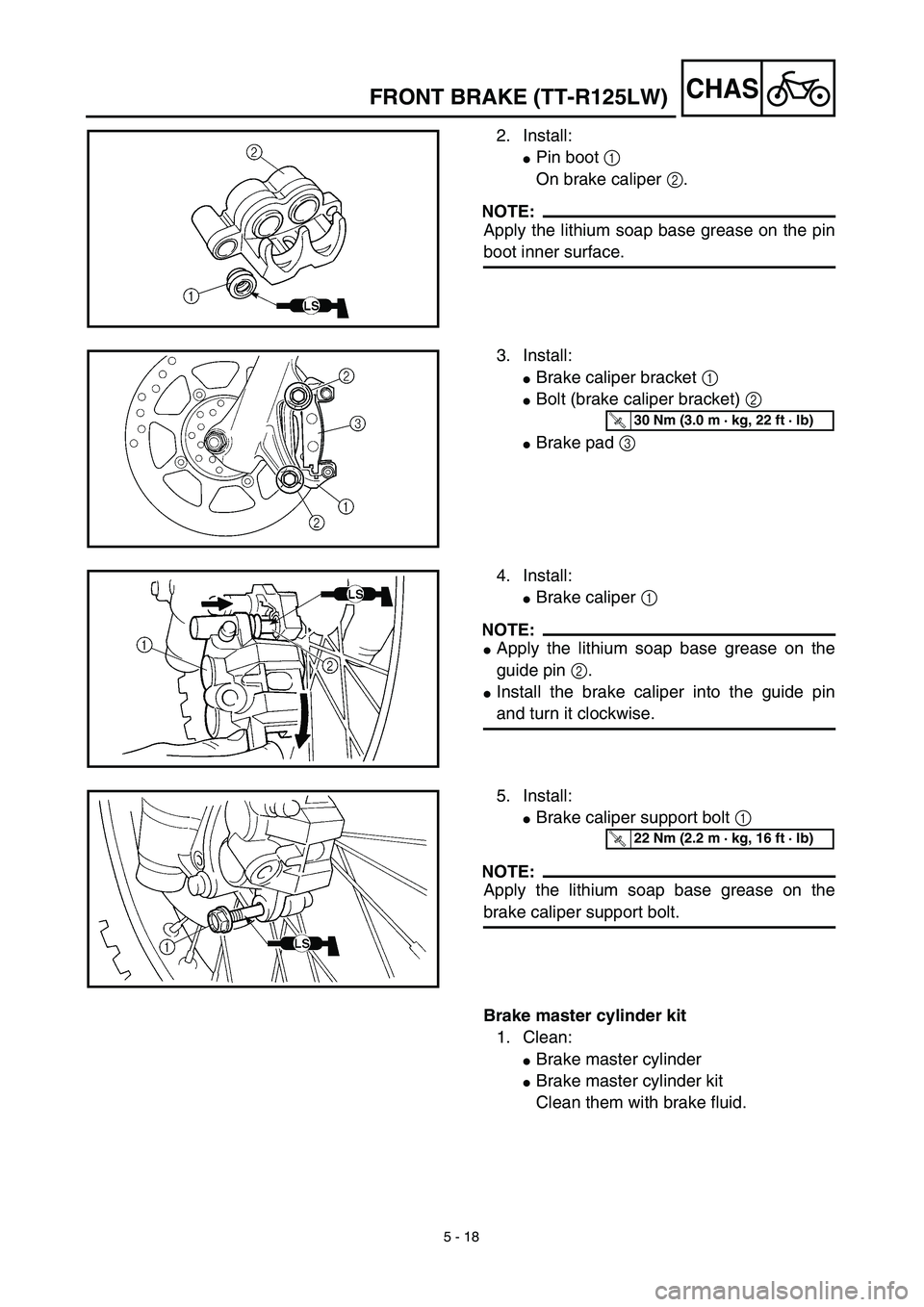
2. Install:
�Pin boot 1
On brake caliper 2.
NOTE:
Apply the lithium soap base grease on the pin
boot inner surface.
3. Install:
�Brake caliper bracket 1
�Bolt (brake caliper bracket) 2
�Brake pad 3
T R..30 Nm (3.0 m · kg, 22 ft · lb)
4. Install:
�Brake caliper 1
NOTE:
�Apply the lithium soap base grease on the
guide pin 2.
�Install the brake caliper into the guide pin
and turn it clockwise.
5. Install:
�Brake caliper support bolt 1
NOTE:
Apply the lithium soap base grease on the
brake caliper support bolt.
T R..22 Nm (2.2 m · kg, 16 ft · lb)
Brake master cylinder kit
1. Clean:
�Brake master cylinder
�Brake master cylinder kit
Clean them with brake fluid.
Page 402 of 510
5 - 19
CHASFRONT BRAKE (TT-R125LW)
2. Install:
�Brake master cylinder cup (primary) 1
�Brake master cylinder cup (secondary) 2
On brake master cylinder piston 3.
NOTE:
Apply the brake fluid on the brake master cyl-
inder cup.
WARNING
After installing, cylinder cup should be
installed as shown direction. Wrong instal-
lation cause improper brake performance.
3. Install:
�Spring 1
On brake master cylinder piston 2.
NOTE:
Install the spring at the smaller diameter side.
4. Install:
�Brake master cylinder kit 1
�Washer 2
�Circlip 3
�Brake master cylinder boot 4
On brake master cylinder 5
NOTE:
�Apply the brake fluid on the brake master
cylinder kit.
�When installing the circlip, use a long nose
circlip pliers.
Page 404 of 510
 5 - 20
CHAS
Brake master cylinder
1. Install:
�Brake master cylinder 1
�Brake master cylinder bracket 2
�Bolt (brake master cylinder bracket) 3
NOTE:
�Install the brake master cylinder bracket so
t")
5 - 20
CHAS
Brake master cylinder
1. Install:
�Brake master cylinder 1
�Brake master cylinder bracket 2
�Bolt (brake master cylinder bracket) 3
NOTE:
�Install the brake master cylinder bracket so
that the arrow mark a face upward.
�First tighten the bolts on the upper side of the
brake master cylinder bracket, and then
tighten the bolts on the lower side.
2. Install:
�Brake lever 1
�Spring 2
�Bolt (brake lever) 3
�Nut (brake lever) 4
NOTE:
�Apply the lithium soap base grease on the
bolt and brake lever sliding surface.
�Apply the molybdenum disulfide grease on
the tip of the adjuster bolt.
T R..9 Nm (0.9 m · kg, 6.5 ft · lb)
T R..7 Nm (0.7 m · kg, 5.1 ft · lb)
T R..7 Nm (0.7 m · kg, 5.1 ft · lb)
Brake hose
1. Install:
�Copper washer 1
�Brake hose 2
�Union bolt 3
WARNING
Always use new copper washers.
CAUTION:
Install the brake hose so that its pipe por-
tion a directs as show and lightly touches
the projection b on the brake caliper.
New
T R..26 Nm (2.6 m · kg, 19 ft · lb)
FRONT BRAKE (TT-R125LW)
Page 406 of 510
5 - 21
CHAS
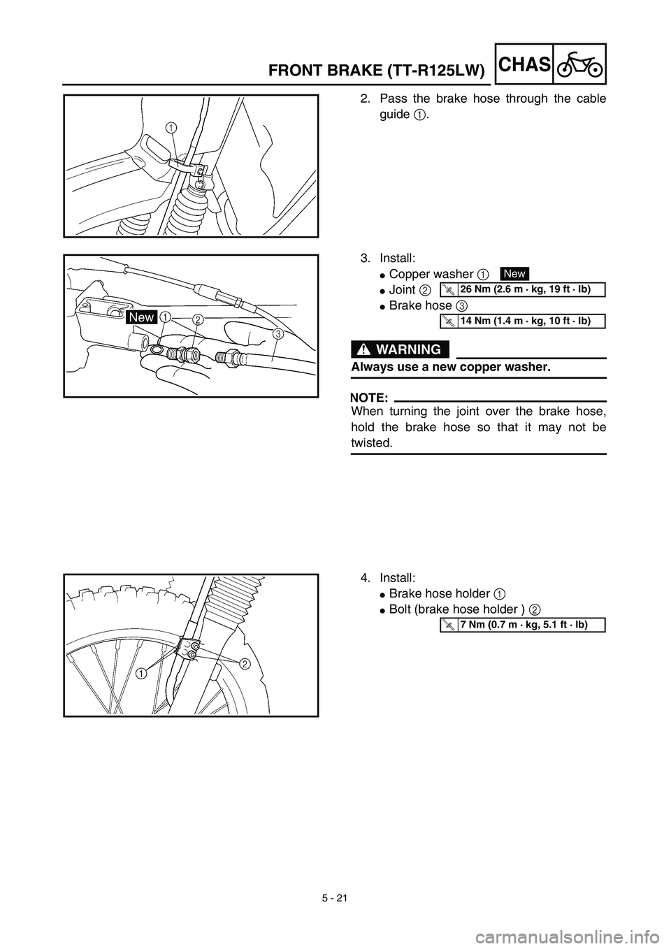
2. Pass the brake hose through the cable
guide 1.
3. Install:
�Copper washer 1
�Joint 2
�Brake hose 3
WARNING
Always use a new copper washer.
NOTE:
When turning the joint over the brake hose,
hold the brake hose so that it may not be
twisted.
New
T R..26 Nm (2.6 m · kg, 19 ft · lb)
T R..14 Nm (1.4 m · kg, 10 ft · lb)
4. Install:
�Brake hose holder 1
�Bolt (brake hose holder ) 2
T R..7 Nm (0.7 m · kg, 5.1 ft · lb)
FRONT BRAKE (TT-R125LW)
Page 408 of 510
5 - 22
CHAS
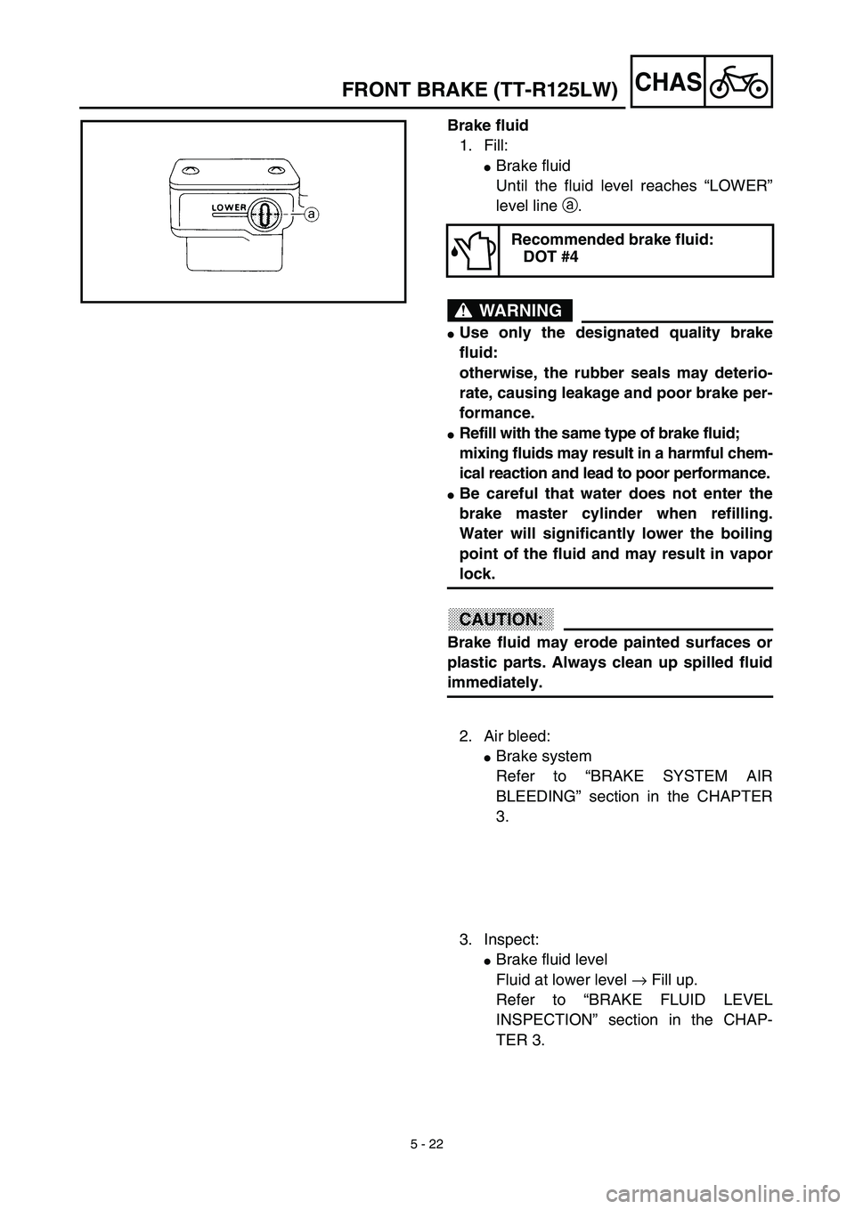
Brake fluid
1. Fill:
�Brake fluid
Until the fluid level reaches “LOWER”
level line a.
WARNING
�Use only the designated quality brake
fluid:
otherwise, the rubber seals may deterio-
rate, causing leakage and poor brake per-
formance.
�Refill with the same type of brake fluid;
mixing fluids may result in a harmful chem-
ical reaction and lead to poor performance.
�Be careful that water does not enter the
brake master cylinder when refilling.
Water will significantly lower the boiling
point of the fluid and may result in vapor
lock.
CAUTION:
Brake fluid may erode painted surfaces or
plastic parts. Always clean up spilled fluid
immediately.
Recommended brake fluid:
DOT #4
2. Air bleed:
�Brake system
Refer to “BRAKE SYSTEM AIR
BLEEDING” section in the CHAPTER
3.
3. Inspect:
�Brake fluid level
Fluid at lower level → Fill up.
Refer to “BRAKE FLUID LEVEL
INSPECTION” section in the CHAP-
TER 3.
FRONT BRAKE (TT-R125LW)
Page 410 of 510
5 - 23
CHAS
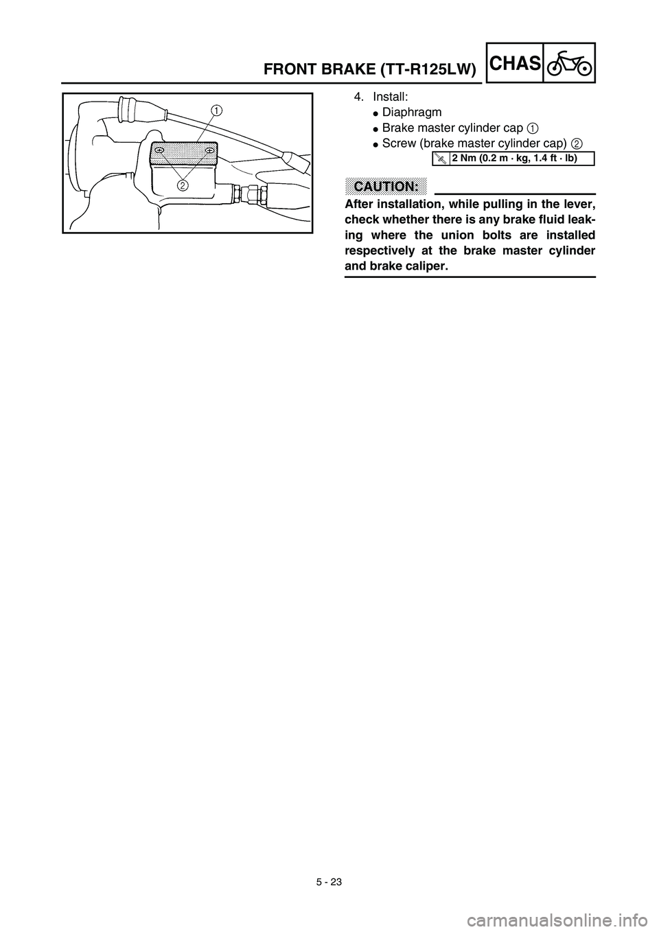
4. Install:
�Diaphragm
�Brake master cylinder cap 1
�Screw (brake master cylinder cap) 2
CAUTION:
After installation, while pulling in the lever,
check whether there is any brake fluid leak-
ing where the union bolts are installed
respectively at the brake master cylinder
and brake caliper.
T R..2 Nm (0.2 m · kg, 1.4 ft · lb)
FRONT BRAKE (TT-R125LW)
Page 412 of 510
5 - 24
CHAS
REAR WHEEL AND REAR BRAKE
Extent of removal:1 Rear wheel removal 2 Wheel bearing removal
3 Brake shoe plate assembly removal and disassembly
Extent of removal Order Part name Q’ty Remarks
Preparation for removalREAR WHEEL AND DRUM
BRAKE
Hold the machine by placing the
suitable stand under the engine.
WARNING
Support the machine securely so there is nodanger of it falling over.
1 Brake rod 1
2 Axle nut 1
3 Drive chain puller (right) 1
4 Wheel axle 1
5 Drive chain puller (left) 1
6 Drive chain 1
7 Rear wheel 1 Refer to “REMOVAL POINTS”.
8 Collar (right) 1
9 Brake shoe plate assembly 1
10Collar (left)
1
231
REAR WHEEL AND REAR BRAKE

 5 - 24
CHAS
REAR WHEEL AND REAR BRAKE
Extent of removal:1 Rear wheel removal 2 Wheel bearing removal
3 Brake shoe plate assembly removal and disassembly
Extent of removal Order Part name Q’ty Remar")