Page 446 of 510
5 - 41
CHASHANDLEBAR
EC5B0000
HANDLEBAR
TT-R125
Extent of removal:1 Handlebar removal
Extent of removal Order Part name Q’ty Remarks
Preparation for removalHANDLEBAR REMOVAL
Number plate
1 Clutch cable 1
2 Clutch lever 1
3 Engine stop switch 1
4 Front brake cable 1
5 Front brake lever 1
6 Grip cap (lower) 1
7 Grip cap (upper) 1
8 Throttle cable 1
9 Throttle grip assembly 1
10 Collar 1
11 Handlebar grip (left) 1 Refer to “REMOVAL POINTS”.
12 Handlebar holder 2
13 Handlebar 1
1
Page 448 of 510
5 - 42
CHASHANDLEBAR
TT-R125LW
Extent of removal:1 Handlebar removal
Extent of removal Order Part name Q’ty Remarks
Preparation for removalHANDLEBAR REMOVAL
Number plate
1 Clutch cable 1
2 Clutch lever 1
3 Engine stop switch 1
4 Brake master cylinder 1 Refer to “REMOVAL POINTS”.
5 Grip cap (lower) 1
6 Grip cap (upper) 1
7 Throttle cable 1
8 Throttle grip assembly 1
1
Page 454 of 510
5 - 45
CHAS
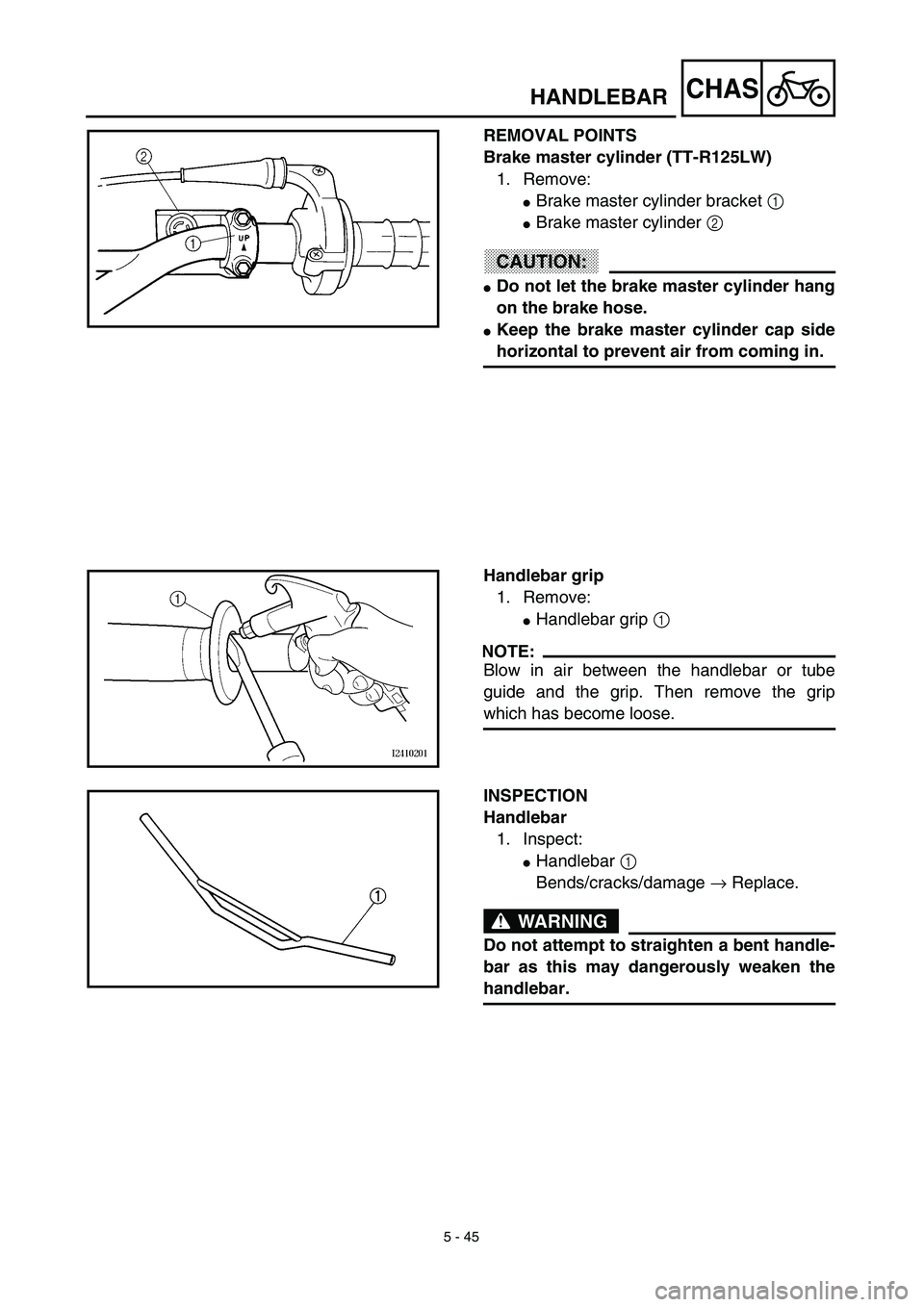
REMOVAL POINTS
Brake master cylinder (TT-R125LW)
1. Remove:
�Brake master cylinder bracket 1
�Brake master cylinder 2
CAUTION:
�Do not let the brake master cylinder hang
on the brake hose.
�Keep the brake master cylinder cap side
horizontal to prevent air from coming in.
Handlebar grip
1. Remove:
�Handlebar grip 1
NOTE:
Blow in air between the handlebar or tube
guide and the grip. Then remove the grip
which has become loose.
INSPECTION
Handlebar
1. Inspect:
�Handlebar 1
Bends/cracks/damage → Replace.
WARNING
Do not attempt to straighten a bent handle-
bar as this may dangerously weaken the
handlebar.
HANDLEBAR
Page 460 of 510
 5 - 48
CHAS
6. Install:
TT-R125
�Front brake lever holder 1
�Bolts (front brake lever holder) 2
�Front brake cable 3
�Clamp
NOTE:
Apply the lithium soap base grease on the
front brake cable end.
TT")
5 - 48
CHAS
6. Install:
TT-R125
�Front brake lever holder 1
�Bolts (front brake lever holder) 2
�Front brake cable 3
�Clamp
NOTE:
Apply the lithium soap base grease on the
front brake cable end.
TT-R125LW
�Brake master cylinder 1
�Brake master cylinder bracket 2
�Bolt (brake master cylinder bracket) 3
NOTE:
�Install the bracket so that the arrow mark a
face upward.
�First tighten the bolts on the upper side of the
brake master cylinder bracket, and then
tighten the bolts on the lower side.
7. Install:
�Engine stop switch 1
�Clutch lever holder 2
�Bolts (clutch lever holder) 3
NOTE:
�The engine stop switch and clutch lever
holder should be installed according to the
dimensions shown.
�Pass the engine stop switch lead in the mid-
dle of the clutch lever holder.
8. Install:
�Clutch cable 1
�Clamp
NOTE:
Apply the lithium soap base grease on the
clutch cable end.
9. Adjust:
�Brake lever free play
Refer to “FRONT BRAKE ADJUST-
MENT” section in the CHAPTER 3.
�Clutch lever free play
Refer to “CLUTCH ADJUSTMENT”
section in the CHAPTER 3.
T R..4 Nm (0.4 m · kg, 2.9 ft · lb)
T R..9 Nm (0.9 m · kg, 6.5 ft · lb)
T R..4 Nm (0.4 m · kg, 2.9 ft · lb)
HANDLEBAR
Page 474 of 510
5 - 55
CHASSWINGARM
EC570000
SWINGARM
Extent of removal:1 Swingarm removal
Extent of removal Order Part name Q’ty Remarks
Preparation for removalSWINGARM REMOVAL
Hold the machine by placing the
suitable stand under the engine.
WARNING
Support the machine securely so there is nodanger of it falling over.
Rear wheel Refer to “REAR WHEEL AND REAR
BRAKE” section.
1 Drive chain tensioner (upper) 1
2 Drive chain tensioner (lower) 1
3 Bolt (connecting arm-frame) 1
4 Bolt (rear shock absorber-relay arm) 1Hold the swingarm.
5 Pivot shaft 1
6 Swingarm 1
1
 5 - 41
CHASHANDLEBAR
EC5B0000
HANDLEBAR
TT-R125
Extent of removal:1 Handlebar removal
Extent of removal Order Part name Q’ty Remarks
Preparation for removalHANDLEBAR REMOVAL
Number plate
1 Clutch ca")
 5 - 42
CHASHANDLEBAR
TT-R125LW
Extent of removal:1 Handlebar removal
Extent of removal Order Part name Q’ty Remarks
Preparation for removalHANDLEBAR REMOVAL
Number plate
1 Clutch cable 1
2 Clutch le")
 5 - 55
CHASSWINGARM
EC570000
SWINGARM
Extent of removal:1 Swingarm removal
Extent of removal Order Part name Q’ty Remarks
Preparation for removalSWINGARM REMOVAL
Hold the machine by placing the
suit")