Page 380 of 510
5 - 8
CHAS
FRONT WHEEL (TT-R125LW)
Extent of removal:1 Front wheel removal2 Wheel bearing removal
3 Brake disc removal
Extent of removal Order Part name Q’ty Remarks
Preparation for removalFRONT WHEEL REMOVAL
Hold the machine by placing the
suitable stand under the engine.
WARNING
Support the machine securely so there is nodanger of it falling over.
1 Axle nut 1
2 Washer 1
3 Wheel axle 1
4 Front wheel 1
5 Collar 2
6 Oil seal 2
7 Wheel bearing 2 Refer to “REMOVAL POINTS”.
8 Spacer 1
9Brake disk
1
2
31
3
FRONT WHEEL (TT-R125LW)
Page 384 of 510
5 - 10
CHASFRONT WHEEL (TT-R125LW)
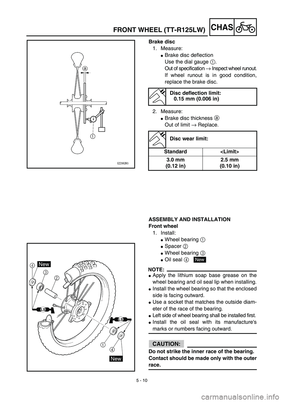
Brake disc
1. Measure:
�Brake disc deflection
Use the dial gauge 1.
Out of specification → Inspect wheel runout.
If wheel runout is in good condition,
replace the brake disc.
2. Measure:
�Brake disc thickness a
Out of limit → Replace.
Disc deflection limit:
0.15 mm (0.006 in)
Disc wear limit:
Standard
3.0 mm
(0.12 in)2.5 mm
(0.10 in)
ASSEMBLY AND INSTALLATION
Front wheel
1. Install:
�Wheel bearing 1
�Spacer 2
�Wheel bearing 3
�Oil seal 4
NOTE:
�Apply the lithium soap base grease on the
wheel bearing and oil seal lip when installing.
�Install the wheel bearing so that the enclosed
side is facing outward.
�Use a socket that matches the outside diam-
eter of the race of the bearing.
�Left side of wheel bearing shall be installed first.
�Install the oil seal with its manufacture's
marks or numbers facing outward.
CAUTION:
Do not strike the inner race of the bearing.
Contact should be made only with the outer
race.
New
Page 386 of 510
5 - 11
CHASFRONT WHEEL (TT-R125LW)
2. Install:
�Brake disc 1
�Bolt (brake disc) 2
NOTE:
Tighten the bolts in stage, using a crisscross
pattern.
T R..12 Nm (1.2 m · kg, 8.7 ft · lb)LT
3. Install:
�Collar 1
NOTE:
�Apply the lithium soap base grease on the oil
seal lips.
�Install the longer collar on the brake disc 2
side.
4. Install:
�Front wheel
NOTE:
Install the brake disc 1 between the brake
pads 2 correctly.
5. Install:
�Wheel axle 1
6. Install:
�Washer 1
�Axle nut 2
T R..45 Nm (4.5 m · kg, 32 ft · lb)
Page 388 of 510
5 - 12
CHAS
FRONT BRAKE (TT-R125LW)
Extent of removal:1 Brake hose removal 2 Brake caliper removal
3 Brake master cylinder removal
Extent of removal Order Part name Q’ty Remarks
Preparation for removalFRONT BRAKE REMOVAL
Hold the machine by placing the
suitable stand under the engine.
Drain the brake fluid.
WARNING
Support the machine securely so there is nodanger of it falling over.
Refer to “REMOVAL POINTS”.
1 Brake hose holder 2
2 Union bolt 1
3 Brake hose 1
4 Joint 1
5 Brake caliper support bolt 1
6 Brake caliper 1 Refer to “REMOVAL POINTS”.
7 Brake lever 1
8 Brake master cylinder bracket 1
9Brake master cylinder
1
3
12
2
3
FRONT BRAKE (TT-R125LW)
Page 390 of 510
5 - 13
CHASFRONT BRAKE (TT-R125LW)
BRAKE CALIPER AND BRAKE MASTER CYLINDER DISASSEMBLY
Extent of removal:1 Brake caliper disassembly2 Brake master cylinder disassembly
Extent of removal Order Part name Q’ty Remarks
Preparation for removalBRAKE CALIPER AND BRAKE
MASTER CYLINDER DISAS-
SEMBLY
Hold the machine by placing the
suitable stand under the engine.
WARNING
Support the machine securely so there is no
danger of it falling over.
1Brake pad 2
2Brake caliper bracket 1
3Brake caliper piston 2 Refer to “REMOVAL POINTS”.
4Brake caliper dust seal 2
Refer to “REMOVAL POINTS”.
5Brake caliper piston seal 2
6Pin boot 1
7Sleeve boot 1
8Brake master cylinder cap 1
9Diaphragm 1
0Brake master cylinder boot 1
ACirclip 1
BWasher 1
CBrake master cylinder kit 1
2
1
Page 392 of 510
 5 - 14
CHASFRONT BRAKE (TT-R125LW)
REMOVAL POINTS
Brake fluid
1. Remove:
�Brake master cylinder cap 1
NOTE:
Do not remove the diaphragm.
2. Connect the transparent hose 2 to the
bleed screw 1 and pla")
5 - 14
CHASFRONT BRAKE (TT-R125LW)
REMOVAL POINTS
Brake fluid
1. Remove:
�Brake master cylinder cap 1
NOTE:
Do not remove the diaphragm.
2. Connect the transparent hose 2 to the
bleed screw 1 and place a suitable con-
tainer under its end.
3. Loosen the bleed screw and drain the
brake fluid while pulling in the lever.
CAUTION:
�Do not reuse the drained brake fluid.
�Brake fluid may erode painted surfaces or
plastic parts. Always clean up spilled
fluid immediately.
Brake caliper
1. Remove:
�Brake caliper 1
NOTE:
Turn the brake caliper counterclockwise and
pull out it from the guide pin 2 on the brake
caliper bracket.
Brake caliper piston
1. Remove:
�Brake caliper piston
Use compressed air and proceed care-
fully.
WARNING
�Cover piston with rag and use extreme
caution when expelling piston from cylin-
der.
�Never attempt to pry out piston.
Brake caliper piston removal steps:
�Insert a piece of rag into the brake caliper
to lock one brake caliper.
�Carefully force the piston out of the brake
caliper cylinder with compressed air.
Page 394 of 510
5 - 15
CHAS
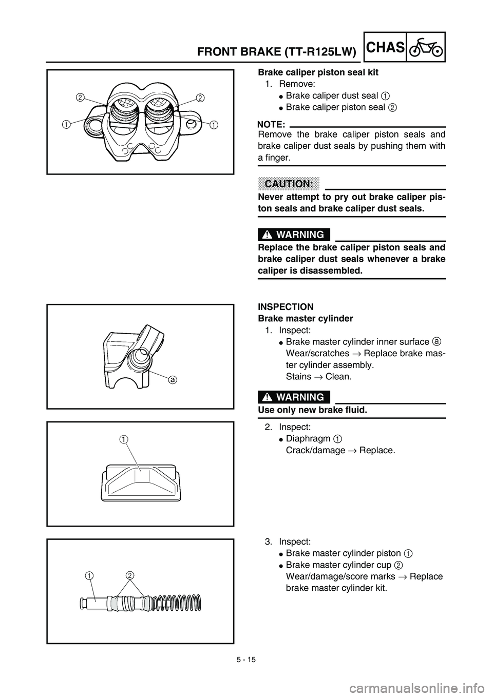
Brake caliper piston seal kit
1. Remove:
�Brake caliper dust seal 1
�Brake caliper piston seal 2
NOTE:
Remove the brake caliper piston seals and
brake caliper dust seals by pushing them with
a finger.
CAUTION:
Never attempt to pry out brake caliper pis-
ton seals and brake caliper dust seals.
WARNING
Replace the brake caliper piston seals and
brake caliper dust seals whenever a brake
caliper is disassembled.
INSPECTION
Brake master cylinder
1. Inspect:
�Brake master cylinder inner surface a
Wear/scratches → Replace brake mas-
ter cylinder assembly.
Stains → Clean.
WARNING
Use only new brake fluid.
2. Inspect:
�Diaphragm 1
Crack/damage → Replace.
3. Inspect:
�Brake master cylinder piston 1
�Brake master cylinder cup 2
Wear/damage/score marks → Replace
brake master cylinder kit.
FRONT BRAKE (TT-R125LW)
Page 396 of 510
5 - 16
CHAS
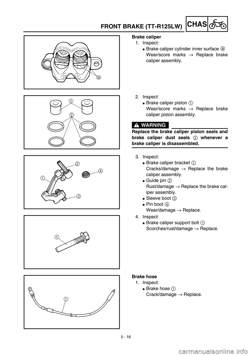
Brake caliper
1. Inspect:
�Brake caliper cylinder inner surface a
Wear/score marks → Replace brake
caliper assembly.
2. Inspect:
�Brake caliper piston 1
Wear/score marks → Replace brake
caliper piston assembly.
WARNING
Replace the brake caliper piston seals and
brake caliper dust seals 2 whenever a
brake caliper is disassembled.
3. Inspect:
�Brake caliper bracket 1
Cracks/damage → Replace the brake
caliper assembly.
�Guide pin 2
Rust/damage → Replace the brake cal-
iper assembly.
�Sleeve boot 3
�Pin boot 4
Wear/damage → Replace.
4. Inspect:
�Brake caliper support bolt 1
Scorches/rust/damage → Replace.
Brake hose
1. Inspect:
�Brake hose 1
Crack/damage → Replace.
FRONT BRAKE (TT-R125LW)
 5 - 8
CHAS
FRONT WHEEL (TT-R125LW)
Extent of removal:1 Front wheel removal2 Wheel bearing removal
3 Brake disc removal
Extent of removal Order Part name Q’ty Remarks
Preparation for removalFRONT WHE")

 5 - 12
CHAS
FRONT BRAKE (TT-R125LW)
Extent of removal:1 Brake hose removal 2 Brake caliper removal
3 Brake master cylinder removal
Extent of removal Order Part name Q’ty Remarks
Preparation for rem")
 5 - 13
CHASFRONT BRAKE (TT-R125LW)
BRAKE CALIPER AND BRAKE MASTER CYLINDER DISASSEMBLY
Extent of removal:1 Brake caliper disassembly2 Brake master cylinder disassembly
Extent of removal Order Part nam")