Page 206 of 510
3 - 28
INSP
ADJ
LUBRICATION
LUBRICATION
To ensure smooth operation of all compo-
nents, lubricate your machine during setup,
after break-in, and after every ride.
1All control cable
2Brake and clutch lever pivots
3Shift pedal pivot
4Footrest pivot
5Throttle-to-handlebar contact
6Drive chain
7Tube guide cable winding portion
8Throttle cable end
9Brake and clutch cable ends
(Clutch cable end only for the TT-R125LW)ÅUse Yamaha cable lube or equivalent on these
areas.
ıUse SAE 10W-30 motor oil or suitable chain
lubricants.
ÇLubricate the following areas with high quality,
lightweight lithium-soap base grease.
AAA
AAB
CC
Page 366 of 510
5 - 1
CHAS
FRONT WHEEL AND FRONT BRAKE (TT-R125)
EC500000
CHASSIS
FRONT WHEEL AND FRONT BRAKE (TT-R125)
Extent of removal:
1
Front wheel removal
2
Wheel bearing removal
3
Brake shoe plate assembly removal and disassembly
Extent of removal Order Part name Q’ty Remarks
Preparation for removal
FRONT WHEEL AND DRUM
BRAKE
Hold the machine by placing the
suitable stand under the engine.
WARNING
Support the machine securely so there is no
danger of it falling over.
1 Brake cable holder 1
2 Brake cable 1 Disconnect at the lever side, first.
3 Axle nut 1
4 Wheel axle 1
5 Front wheel 1
6 Collar set 1
7 Brake shoe plate assembly 1
8 Oil seal 1
9 Wheel bearing 2 Refer to “REMOVAL POINTS”.
10Spacer
1
2
3
1
Page 368 of 510
5 - 2
CHAS
FRONT WHEEL AND FRONT BRAKE (TT-R125)
Extent of removal Order Part name Q’ty Remarks
11 Brake shoe 2
12 Spring 2
13 Brake camshaft lever 1
14 Wear indicator plate 1
15 Brake camshaft 1
16 Brake shoe plate 1
3
Page 370 of 510
5 - 3
CHAS
FRONT WHEEL AND FRONT BRAKE (TT-R125)
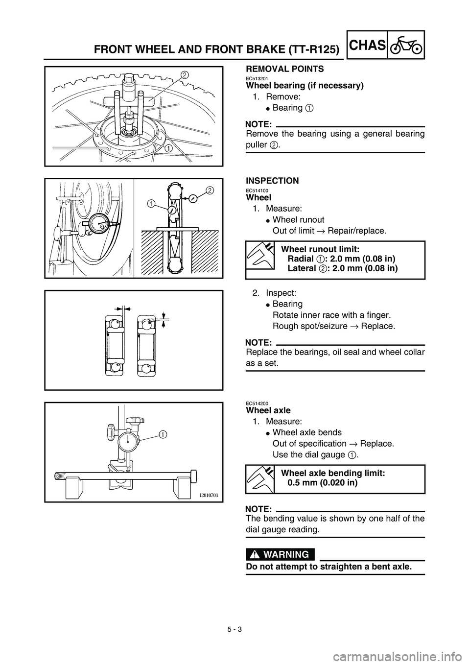
REMOVAL POINTS
EC513201
Wheel bearing (if necessary)
1. Remove:
�
Bearing
1
NOTE:
Remove the bearing using a general bearing
puller
2
.
INSPECTION
EC514100
Wheel
1. Measure:
�
Wheel runout
Out of limit
→
Repair/replace.
Wheel runout limit:
Radial
1
: 2.0 mm (0.08 in)
Lateral
2
: 2.0 mm (0.08 in)
2. Inspect:
�
Bearing
Rotate inner race with a finger.
Rough spot/seizure
→
Replace.
NOTE:
Replace the bearings, oil seal and wheel collar
as a set.
EC514200
Wheel axle
1. Measure:
�
Wheel axle bends
Out of specification
→
Replace.
Use the dial gauge
1
.
NOTE:
The bending value is shown by one half of the
dial gauge reading.
WARNING
Do not attempt to straighten a bent axle.
Wheel axle bending limit:
0.5 mm (0.020 in)
Page 372 of 510
5 - 4
CHAS
FRONT WHEEL AND FRONT BRAKE (TT-R125)
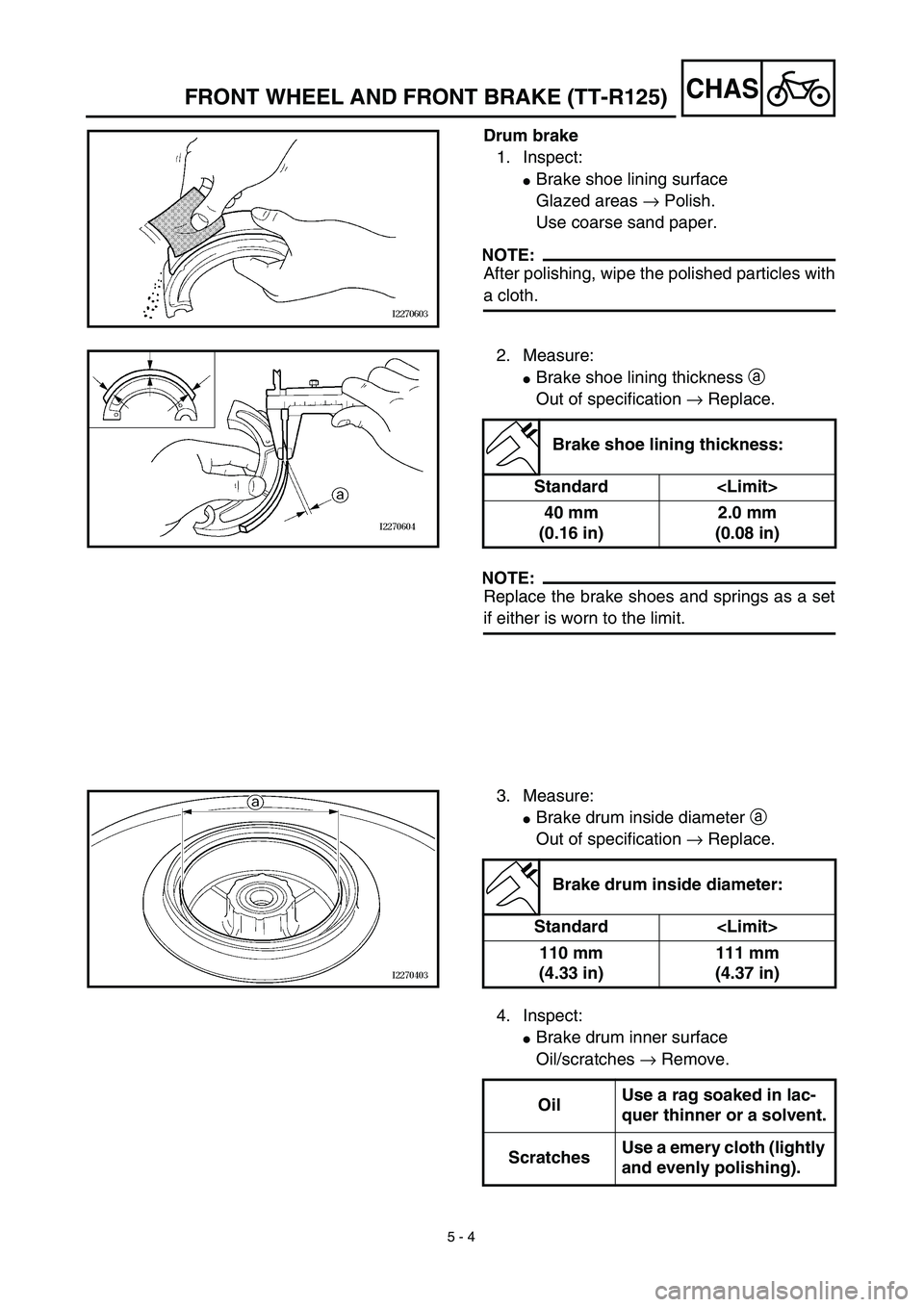
Drum brake
1. Inspect:
�
Brake shoe lining surface
Glazed areas
→
Polish.
Use coarse sand paper.
NOTE:
After polishing, wipe the polished particles with
a cloth.
2. Measure:
�
Brake shoe lining thickness
a
Out of specification
→
Replace.
NOTE:
Replace the brake shoes and springs as a set
if either is worn to the limit.
Brake shoe lining thickness:
Standard
40 mm
(0.16 in)2.0 mm
(0.08 in)
3. Measure:
�
Brake drum inside diameter
a
Out of specification
→
Replace.
Brake drum inside diameter:
Standard
110 mm
(4.33 in)111 mm
(4.37 in)
4. Inspect:
�
Brake drum inner surface
Oil/scratches
→
Remove.
OilUse a rag soaked in lac-
quer thinner or a solvent.
ScratchesUse a emery cloth (lightly
and evenly polishing).
Page 374 of 510
5 - 5
CHAS
FRONT WHEEL AND FRONT BRAKE (TT-R125)
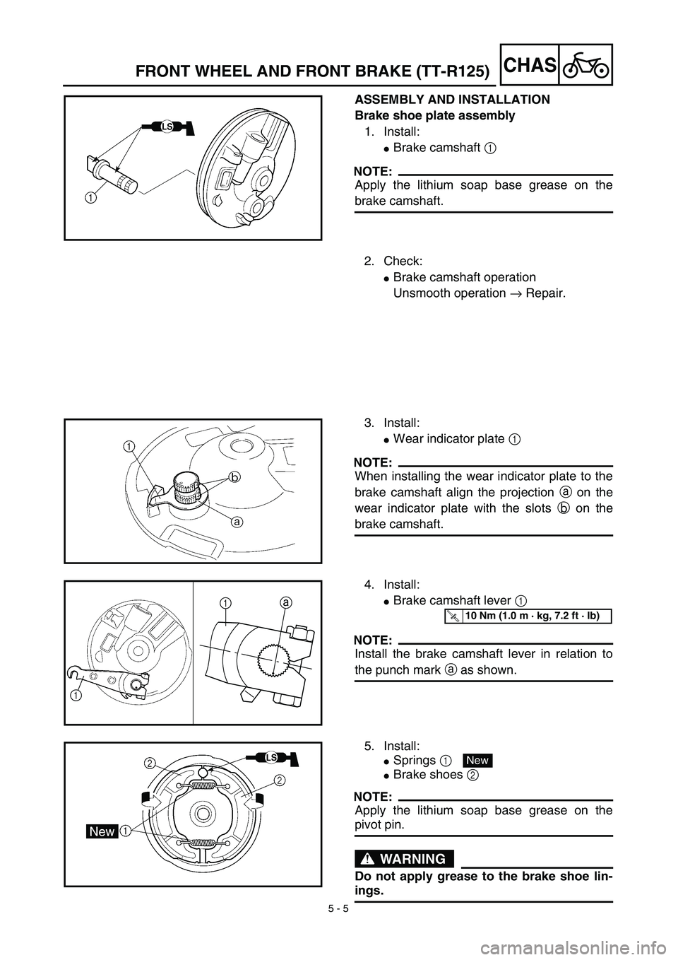
ASSEMBLY AND INSTALLATION
Brake shoe plate assembly
1. Install:
�
Brake camshaft
1
NOTE:
Apply the lithium soap base grease on the
brake camshaft.
2. Check:
�
Brake camshaft operation
Unsmooth operation
→
Repair.
3. Install:
�
Wear indicator plate
1
NOTE:
When installing the wear indicator plate to the
brake camshaft align the projection
a
on the
wear indicator plate with the slots
b
on the
brake camshaft.
4. Install:
�
Brake camshaft lever
1
NOTE:
Install the brake camshaft lever in relation to
the punch mark
a
as shown.
1
1a
T R..10 Nm (1.0 m · kg, 7.2 ft · lb)
5. Install:
�
Springs
1
�
Brake shoes 2
NOTE:
Apply the lithium soap base grease on the
pivot pin.
WARNING
Do not apply grease to the brake shoe lin-
ings.
New
Page 376 of 510
5 - 6
CHASFRONT WHEEL AND FRONT BRAKE (TT-R125)
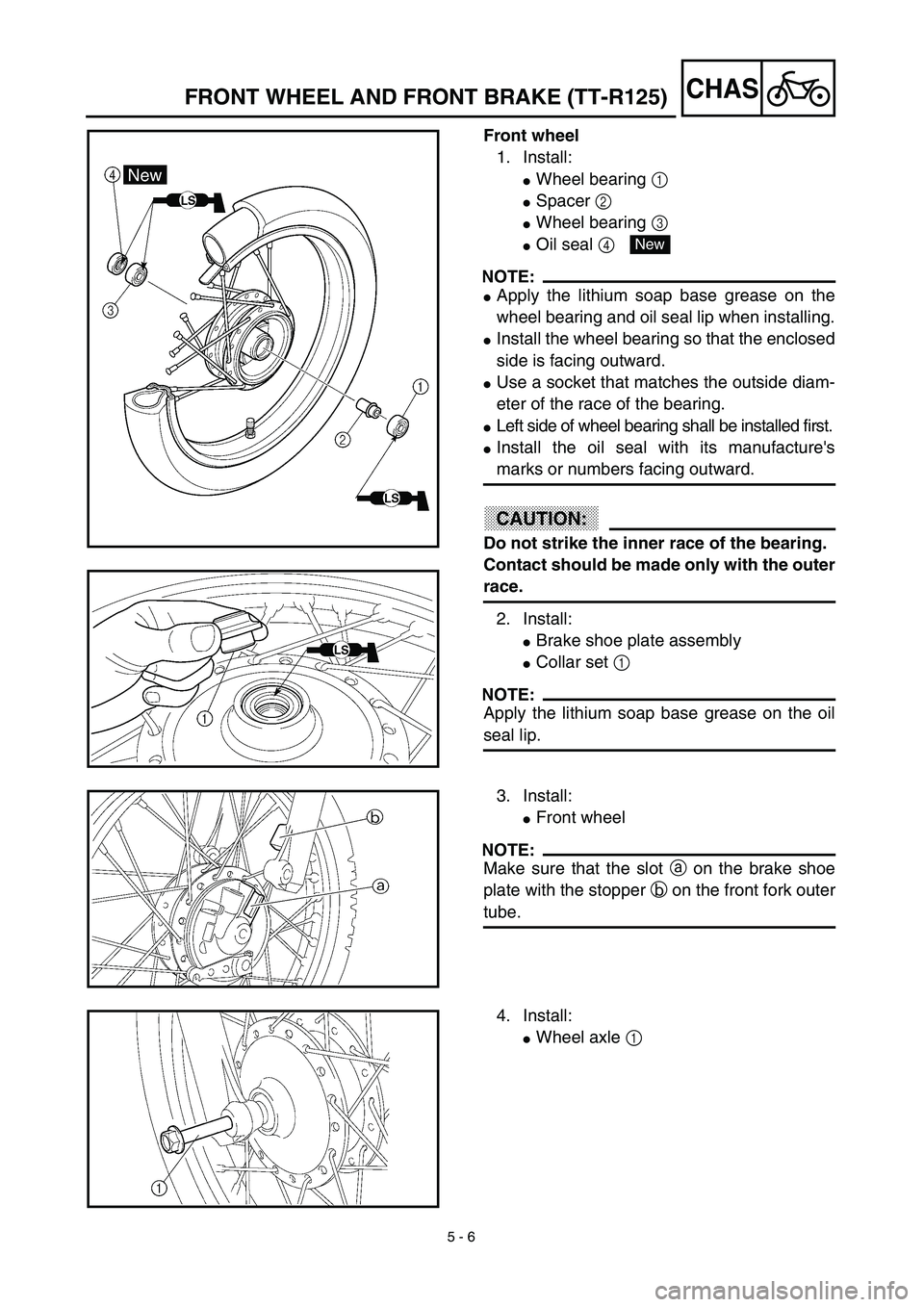
Front wheel
1. Install:
�Wheel bearing 1
�Spacer 2
�Wheel bearing 3
�Oil seal 4
NOTE:
�Apply the lithium soap base grease on the
wheel bearing and oil seal lip when installing.
�Install the wheel bearing so that the enclosed
side is facing outward.
�Use a socket that matches the outside diam-
eter of the race of the bearing.
�Left side of wheel bearing shall be installed first.
�Install the oil seal with its manufacture's
marks or numbers facing outward.
CAUTION:
Do not strike the inner race of the bearing.
Contact should be made only with the outer
race.
2. Install:
�Brake shoe plate assembly
�Collar set 1
NOTE:
Apply the lithium soap base grease on the oil
seal lip.
New
3. Install:
�Front wheel
NOTE:
Make sure that the slot a on the brake shoe
plate with the stopper b on the front fork outer
tube.
4. Install:
�Wheel axle 1
Page 378 of 510
5 - 7
CHASFRONT WHEEL AND FRONT BRAKE (TT-R125)
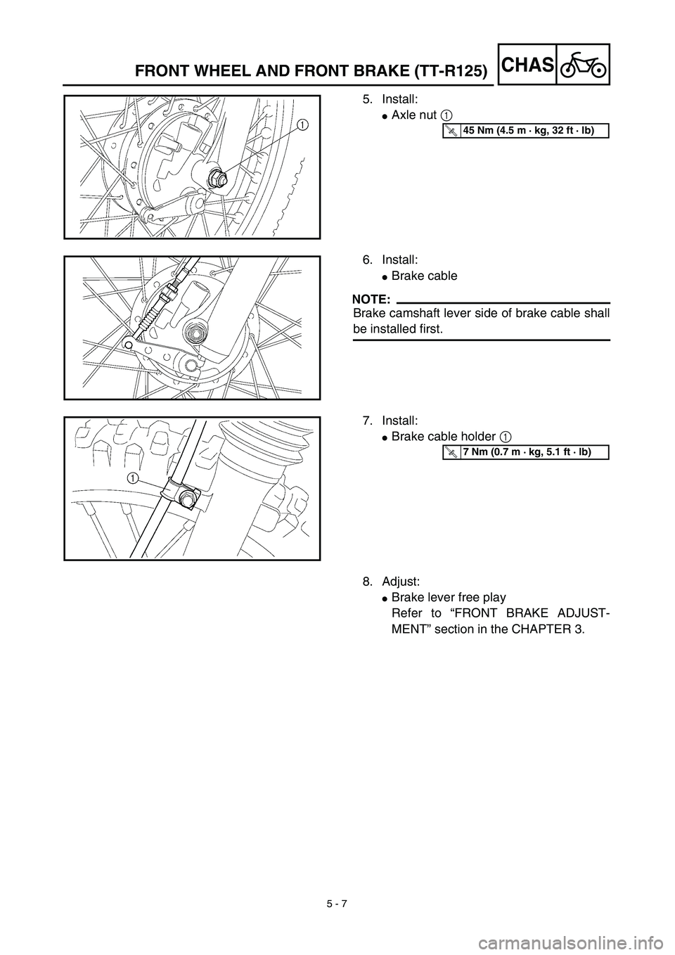
5. Install:
�Axle nut 1
T R..45 Nm (4.5 m · kg, 32 ft · lb)
6. Install:
�Brake cable
NOTE:
Brake camshaft lever side of brake cable shall
be installed first.
7. Install:
�Brake cable holder 1
T R..7 Nm (0.7 m · kg, 5.1 ft · lb)
8. Adjust:
�Brake lever free play
Refer to “FRONT BRAKE ADJUST-
MENT” section in the CHAPTER 3.
 3 - 28
INSP
ADJ
LUBRICATION
LUBRICATION
To ensure smooth operation of all compo-
nents, lubricate your machine during setup,
after break-in, and after every ride.
1All control cable
2Brake and clutch")

5 - 1
CHAS
FRONT WHEEL AND FRONT BRAKE (TT-R125)
EC500000
CHASSIS
FRONT WHEEL AND FRONT BRAKE (TT-R125)
Extent of removal:
1
Front wheel removal
2
Wheel bearing removal
3
Brake")

5 - 2
CHAS
FRONT WHEEL AND FRONT BRAKE (TT-R125)
Extent of removal Order Part name Q’ty Remarks
11 Brake shoe 2
12 Spring 2
13 Brake camshaft lever 1
14 Wear indicator plate 1
15 Brake camshaft")