Page 154 of 510
 3 - 3
INSP
ADJ
PRE-OPERATION INSPECTION AND MAINTENANCE
PRE-OPERATION INSPECTION AND MAINTENANCE
Before riding for break-in operation or practice, make sure the machine is in good operating condi-
tio")
3 - 3
INSP
ADJ
PRE-OPERATION INSPECTION AND MAINTENANCE
PRE-OPERATION INSPECTION AND MAINTENANCE
Before riding for break-in operation or practice, make sure the machine is in good operating condi-
tion.
Before using this machine, check the following points.
GENERAL INSPECTION AND MAINTENANCE
Item Routine Page
FuelCheck that a fresh gasoline is filled in the fuel tank. Check the
fuel line for leakage.P.1-12
Engine oilCheck that the oil level is correct. Check the crankcase for leak-
age.P.3-7 ~ 10
Gear shifter and clutchCheck that gears can be shifted correctly in order and that the
clutch operates smoothly.P.3-4
Throttle grip/housingCheck that the throttle grip operation and free play are correctly
adjusted. Lubricate the throttle grip and housing, if necessary.P.3-4 ~ 5
BrakesCheck the play of front and rear brake and effect of front and
rear brake.
Check fluid level and leakage. (TT-R125LW only)P.3-15 ~ 20
Drive chainCheck chain slack and alignment. Check that the chain is lubri-
cated properly.P.3-21 ~ 22
WheelsCheck for excessive wear and tire pressure. Check for loose
spokes and have no excessive play.P.3-24 ~ 25
SteeringCheck that the handlebar can be turned smoothly and have no
excessive play.P.3-25 ~ 27
Front forks and rear shock
absorber assemblyCheck that they operate smoothly and there is no oil leakage. P.3-23 ~ 24
Cables (wires)Check that the clutch and throttle cables move smoothly. Check
that they are not caught when the handlebars are turned or
when the front forks travel up and down.—
Muffler Check that the muffler is tightly mounted and has no cracks. P.4-2
Sprocket Check that the driven sprocket tightening nut is not loose. P.3-20
Lubrication Check for smooth operation. Lubricate if necessary. P.3-28
Bolts and nuts Check the chassis and engine for loose bolts and nuts.—
Lead connectorsCheck that the CDI magneto, CDI unit, and ignition coil are con-
nected tightly.P.1-5
Page 180 of 510
 3 - 15
INSP
ADJ
EC360000
CHASSIS
EC361012
BRAKE SYSTEM AIR BLEEDING (TT-R125LW)
WARNING
Bleed the brake system if:
�The system has been disassembled.
�A brake hose has been loosened or
removed.
�The b")
3 - 15
INSP
ADJ
EC360000
CHASSIS
EC361012
BRAKE SYSTEM AIR BLEEDING (TT-R125LW)
WARNING
Bleed the brake system if:
�The system has been disassembled.
�A brake hose has been loosened or
removed.
�The brake fluid is very low.
�The brake operation is faulty.
A dangerous loss of braking performance
may occur if the brake system is not prop-
erly bleed.
1. Remove:
�Brake master cylinder cap
�Diaphragm
2. Bleed:
�Brake fluid
Air bleeding steps:
a. Add proper brake fluid to the reservoir.
b. Install the diaphragm. Be careful not to
spill any fluid or allow the reservoir to
overflow.
c. Connect the clear plastic tube 2 tightly
to the caliper bleed screw 1.
d. Place the other end of the tube into a
container.
e. Slowly apply the brake lever several
times.
f. Pull in the lever. Hold the lever in posi-
tion.
g. Loosen the bleed screw and allow the
lever to travel towards its limit.
h. Tighten the bleed screw when the lever
limit has been reached; then release the
lever.
T R..
Bleed screw:
6 Nm (0.6 m • kg, 4.3 ft • lb)
i. Repeat steps (e) to (h) until of the air
bubbles have been removed from the
system.
CHASSIS/BRAKE SYSTEM AIR BLEEDING (TT-R125LW)
Page 182 of 510
3 - 16
INSP
ADJ
3. Install:
�Diaphragm
�Brake master cylinder cap
NOTE:
If bleeding is difficult, it may be necessary to
let the brake fluid system stabilize for a few
hours. Repeat the bleeding procedure when
the tiny bubbles in the system have disap-
peared.
j. Add brake fluid to the level line on the
reservoir.
WARNING
Check the operation of the brake after
bleeding the brake system.
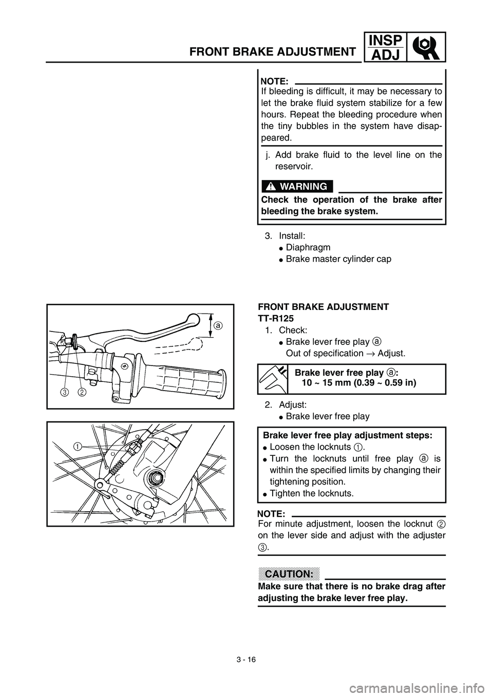
FRONT BRAKE ADJUSTMENT
TT-R125
1. Check:
�Brake lever free play a
Out of specification → Adjust.
2. Adjust:
�Brake lever free play
NOTE:
For minute adjustment, loosen the locknut 2
on the lever side and adjust with the adjuster
3.
CAUTION:
Make sure that there is no brake drag after
adjusting the brake lever free play.
Brake lever free play a:
10 ~ 15 mm (0.39 ~ 0.59 in)
Brake lever free play adjustment steps:
�Loosen the locknuts 1.
�Turn the locknuts until free play a is
within the specified limits by changing their
tightening position.
�Tighten the locknuts.
FRONT BRAKE ADJUSTMENT
Page 184 of 510
3 - 17
INSP
ADJ
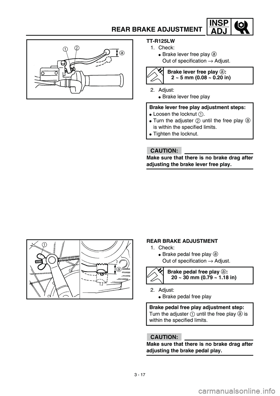
TT-R125LW
1. Check:
�Brake lever free play a
Out of specification → Adjust.
2. Adjust:
�Brake lever free play
CAUTION:
Make sure that there is no brake drag after
adjusting the brake lever free play.
Brake lever free play a:
2 ~ 5 mm (0.08 ~ 0.20 in)
Brake lever free play adjustment steps:
�Loosen the locknut 1.
�Turn the adjuster 2 until the free play a
is within the specified limits.
�Tighten the locknut.
REAR BRAKE ADJUSTMENT
1. Check:
�Brake pedal free play a
Out of specification → Adjust.
2. Adjust:
�Brake pedal free play
CAUTION:
Make sure that there is no brake drag after
adjusting the brake pedal play.
Brake pedal free play a:
20 ~ 30 mm (0.79 ~ 1.18 in)
Brake pedal free play adjustment step:
Turn the adjuster 1 until the free play a is
within the specified limits.
REAR BRAKE ADJUSTMENT
Page 186 of 510
3 - 18
INSP
ADJ
BRAKE PEDAL HEIGHT ADJUSTMENT
1. Check:
�Brake pedal height a
Out of specification → Adjust.
2. Adjust:
�Brake pedal height
FRONT BRAKE PAD INSPECTION AND
REPLACEMENT (TT-R125LW)
1. Remove:
�Plug
2. Inspect:
�Brake pad thickness a
Out of specification → Replace as a set.
Brake pedal height a:
1 mm (0.04 in)
Pedal height adjustment steps:
�Loosen the locknut 1.
�Turn the adjusting bolt 2 until the pedal
height a is within specified height.
�Tighten the locknut.
Brake pad thickness a:
Standard
4.0 mm
(0.16 in)0.8 mm
(0.03 in)
3. Replace:
�Brake pad
Brake pad replacement steps:
�Remove the brake caliper support bolt 1.
�Turn the brake caliper 2 counterclock-
wise a.
�Replace the brake pads 3.
BRAKE PEDAL HEIGHT ADJUSTMENT/FRONT BRAKE
PAD INSPECTION AND REPLACEMENT (TT-R125LW)
Page 188 of 510
 3 - 19
INSP
ADJ
4. Inspect:
�Brake fluid level
Refer to “BRAKE FLUID LEVEL
INSPECTION” section in the CHAP-
TER 3.
5. Check:
�Brake lever operation
A softy or spongy feeling → Bleed
brake system")
3 - 19
INSP
ADJ
4. Inspect:
�Brake fluid level
Refer to “BRAKE FLUID LEVEL
INSPECTION” section in the CHAP-
TER 3.
5. Check:
�Brake lever operation
A softy or spongy feeling → Bleed
brake system.
Refer to “BRAKE SYSTEM AIR
BLEEDING” section.
FRONT BRAKE SHOE INSPECTION (TT-R125)
1. Inspect:
�Brake shoe lining wear limit
�Connect the transparent hose 4 to the
bleed screw 5 and place the suitable con-
tainer under its end.
�Loosen the bleed screw and push the
brake caliper piston in.
CAUTION:
Do not reuse the drained brake fluid.
�Tighten the bleed screw.
T R..
Bleed screw:
6 Nm (0.6 m • kg, 4.3 ft • lb)
�Install the brake caliper 6 and brake cali-
per support bolt 7.
NOTE:
Apply the lithium soap base grease on the
caliper support bolt.
T R..
Brake caliper support bolt:
22 Nm (2.2 m • kg, 16 ft • lb)
Brake shoe lining wear limit checking
steps:
�Fully pull in the brake lever and hold it in
position.
�Then check the brake shoe wear indicator
1 is within the wear limit a.
Outside the limit → Replace the brake
shoe.
Refer to “FRONT WHEEL AND FRONT
BRAKE” section in the CHAPTER 5.
FRONT BRAKE SHOE INSPECTION (TT-R125)
Page 190 of 510
 3 - 20
INSP
ADJ
REAR BRAKE SHOE INSPECTION
1. Inspect:
�Brake shoe lining wear limit
BRAKE FLUID LEVEL INSPECTION
(TT-R125LW)
1. Place the brake master cylinder so that
its top is in a horizontal posi")
3 - 20
INSP
ADJ
REAR BRAKE SHOE INSPECTION
1. Inspect:
�Brake shoe lining wear limit
BRAKE FLUID LEVEL INSPECTION
(TT-R125LW)
1. Place the brake master cylinder so that
its top is in a horizontal position.
2. Inspect:
�Brake fluid level
Fluid at lower level → Fill up.
aLower level
WARNING
�Use only designated quality brake fluid to
avoid poor brake performance.
�Refill with same type and brand of brake
fluid; mixing fluids could result in poor
brake performance.
�Be sure that water or other contaminants
do not enter brake master cylinder when
refilling.
�Clean up spilled fluid immediately to
avoid erosion of painted surfaces or plas-
tic parts. Brake shoe lining wear limit checking
steps:
�Fully push down the brake pedal and hold
it in position.
�Then check the brake shoe wear indicator
1 is within the wear limit a.
Outside the limit → Replace the brake
shoe.
Refer to “REAR WHEEL AND REAR BRAKE”
section in the CHAPTER 5.
Recommended brake fluid:
DOT #4
SPROCKETS INSPECTION
1. Inspect:
�Sprocket teeth a
Excessive wear → Replace.
NOTE:
Replace the drive, driven sprockets and drive
chain as a set.
REAR BRAKE SHOE INSPECTION/BRAKE FLUID LEVEL
INSPECTION (TT-R125LW)/SPROCKETS INSPECTION
Page 196 of 510
3 - 23
INSP
ADJ
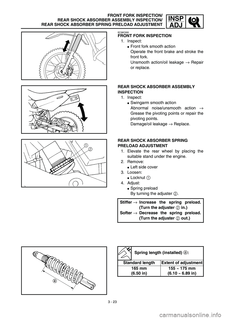
FRONT FORK INSPECTION/
REAR SHOCK ABSORBER ASSEMBLY INSPECTION/
REAR SHOCK ABSORBER SPRING PRELOAD ADJUSTMENT
EC36C000
FRONT FORK INSPECTION
1. Inspect:
�Front fork smooth action
Operate the front brake and stroke the
front fork.
Unsmooth action/oil leakage → Repair
or replace.
REAR SHOCK ABSORBER ASSEMBLY
INSPECTION
1. Inspect:
�Swingarm smooth action
Abnormal noise/unsmooth action →
Grease the pivoting points or repair the
pivoting points.
Damage/oil leakage → Replace.
REAR SHOCK ABSORBER SPRING
PRELOAD ADJUSTMENT
1. Elevate the rear wheel by placing the
suitable stand under the engine.
2. Remove:
�Left side cover
3. Loosen:
�Locknut 1
4. Adjust:
�Spring preload
By turning the adjuster 2.
Stiffer →Increase the spring preload.
(Turn the adjuster 2 in.)
Softer →Decrease the spring preload.
(Turn the adjuster 2 out.)
Spring length (installed) a:
Standard length Extent of adjustment
165 mm
(6.50 in)155 ~ 175 mm
(6.10 ~ 6.89 in)