Page 250 of 510
4 - 21
ENGCAMSHAFT AND ROCKER ARMS
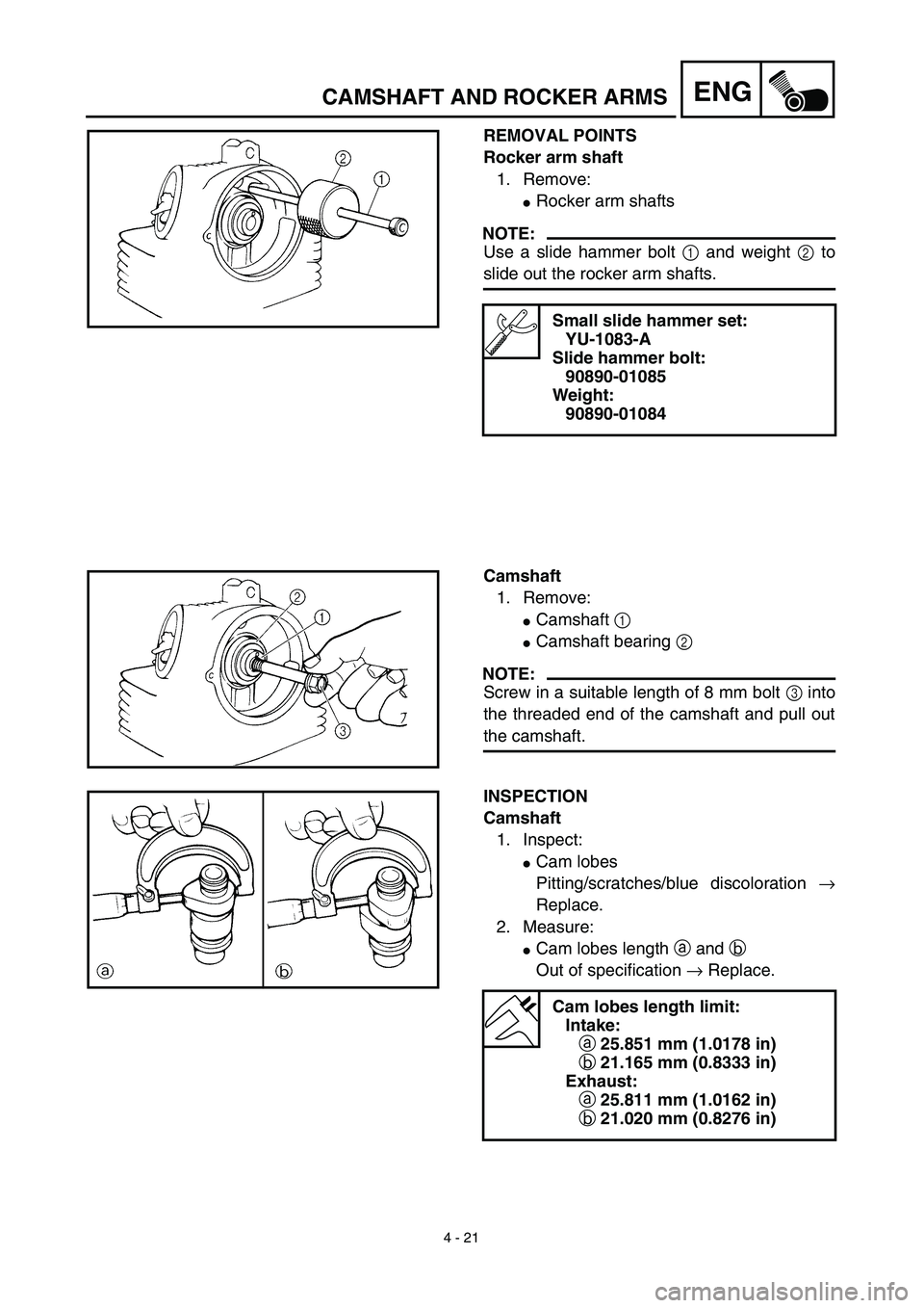
REMOVAL POINTS
Rocker arm shaft
1. Remove:
�Rocker arm shafts
NOTE:
Use a slide hammer bolt 1 and weight 2 to
slide out the rocker arm shafts.
Small slide hammer set:
YU-1083-A
Slide hammer bolt:
90890-01085
Weight:
90890-01084
Camshaft
1. Remove:
�Camshaft 1
�Camshaft bearing 2
NOTE:
Screw in a suitable length of 8 mm bolt 3 into
the threaded end of the camshaft and pull out
the camshaft.
INSPECTION
Camshaft
1. Inspect:
�Cam lobes
Pitting/scratches/blue discoloration →
Replace.
2. Measure:
�Cam lobes length a and b
Out of specification → Replace.
Cam lobes length limit:
Intake:
a 25.851 mm (1.0178 in)
b 21.165 mm (0.8333 in)
Exhaust:
a 25.811 mm (1.0162 in)
b 21.020 mm (0.8276 in)
Page 252 of 510
4 - 22
ENGCAMSHAFT AND ROCKER ARMS
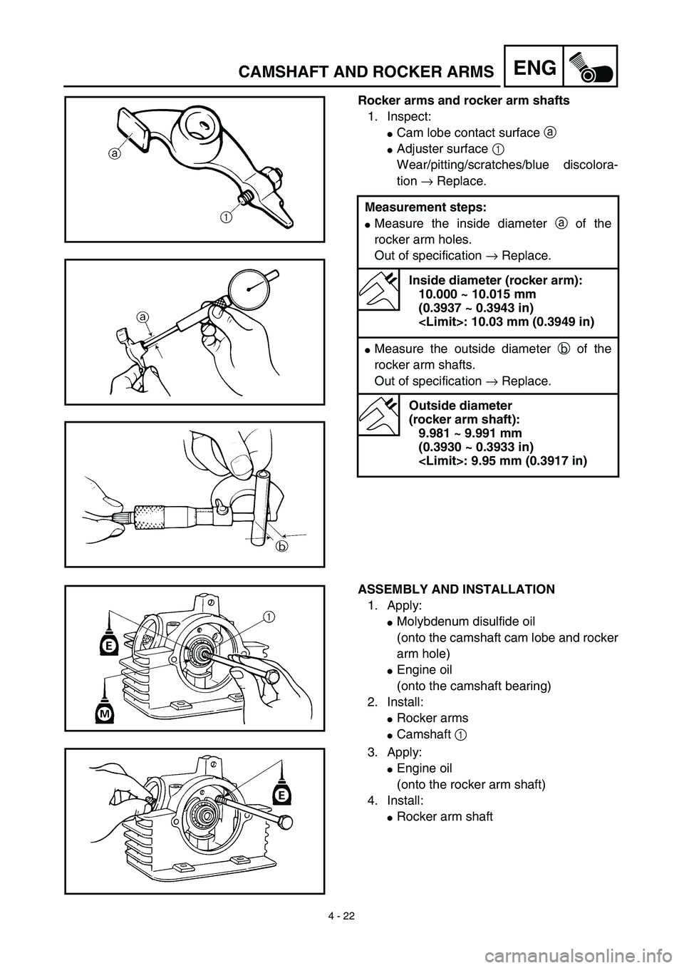
Rocker arms and rocker arm shafts
1. Inspect:
�Cam lobe contact surface a
�Adjuster surface 1
Wear/pitting/scratches/blue discolora-
tion → Replace.
Measurement steps:
�Measure the inside diameter a of the
rocker arm holes.
Out of specification → Replace.
Inside diameter (rocker arm):
10.000 ~ 10.015 mm
(0.3937 ~ 0.3943 in)
: 10.03 mm (0.3949 in)
�Measure the outside diameter b of the
rocker arm shafts.
Out of specification → Replace.
Outside diameter
(rocker arm shaft):
9.981 ~ 9.991 mm
(0.3930 ~ 0.3933 in)
: 9.95 mm (0.3917 in)
ASSEMBLY AND INSTALLATION
1. Apply:
�Molybdenum disulfide oil
(onto the camshaft cam lobe and rocker
arm hole)
�Engine oil
(onto the camshaft bearing)
2. Install:
�Rocker arms
�Camshaft 1
3. Apply:
�Engine oil
(onto the rocker arm shaft)
4. Install:
�Rocker arm shaft
Page 264 of 510
 4 - 28
ENGVALVES AND VALVE SPRINGS
8. Measure:
�Valve seat width a
Out of specification → Reface the valve
seat.
Valve seat width:
Intake:
0.9 ~ 1.1 mm (0.0354 ~ 0.0433 in)
<Limit>: 1.6 mm (0.0630")
4 - 28
ENGVALVES AND VALVE SPRINGS
8. Measure:
�Valve seat width a
Out of specification → Reface the valve
seat.
Valve seat width:
Intake:
0.9 ~ 1.1 mm (0.0354 ~ 0.0433 in)
: 1.6 mm (0.0630 in)
Exhaust:
0.9 ~ 1.1 mm (0.0354 ~ 0.0433 in)
: 1.6 mm (0.0630 in)
Measurement steps:
�Apply Mechanic’s blueing dye (Dykem) b
to the valve face.
�Install the valve into the cylinder head.
�Press the valve through the valve guide
and onto the valve seat to make a clear
pattern.
�Measure the valve seat width. Where the
valve seat and valve face made contact,
blueing will have been removed.
�If the valve seat is too wide, too narrow, or
the seat is not centered, the valve seat
must be refaced.
9. Lap:
�Valve face
�Valve seat
NOTE:
After refacing the valve seat or replacing the
valve and valve guide, the valve seat and
valve face should be lapped.
Lapping steps:
�Apply a coarse lapping compound to the
valve face.
CAUTION:
Do not let the compound enter the gap
between the valve stem and the valve
guide.
�Apply molybdenum disulfide oil to the
valve stem.
Page 266 of 510
 4 - 29
ENGVALVES AND VALVE SPRINGS
�Install the valve into the cylinder head.
�Turn the valve until the valve face and
valve seat are evenly polished, then clean
off all of the compound.
NOTE:
For bes")
4 - 29
ENGVALVES AND VALVE SPRINGS
�Install the valve into the cylinder head.
�Turn the valve until the valve face and
valve seat are evenly polished, then clean
off all of the compound.
NOTE:
For best lapping results, lightly tap the valve
seat while rotating the valve back and forth
between your hands.
�Apply a fine lapping compound to the
valve face and repeat the above steps.
NOTE:
After every lapping operation be sure to
clean off all of the compound from the valve
face and valve seat.
�Apply Mechanic’s blueing dye (Dykem) to
the valve face.
�Install the valve into the cylinder head.
�Press the valve through the valve guide
and onto the valve seat to make a clear
pattern.
�Measure the valve seat width again. If the
valve seat width is out of specification,
reface and re-lap the valve seat.
Valve spring
1. Measure:
�Valve spring free length a
Out of specification → Replace.
Free length (valve spring):
Intake:
32.55 mm (1.28 in)
: 31.2 mm (1.23 in)
Exhaust:
32.55 mm (1.28 in)
: 31.2 mm (1.23 in)
Page 278 of 510
4 - 35
ENGCYLINDER AND PISTON
�If out of specification, replace the cylinder,
and replace the piston and piston rings as
a set.
Piston pin
1. Inspect:
�Piston pin
Blue discoloration/grooves → Replace,
then inspect the lubrication system.
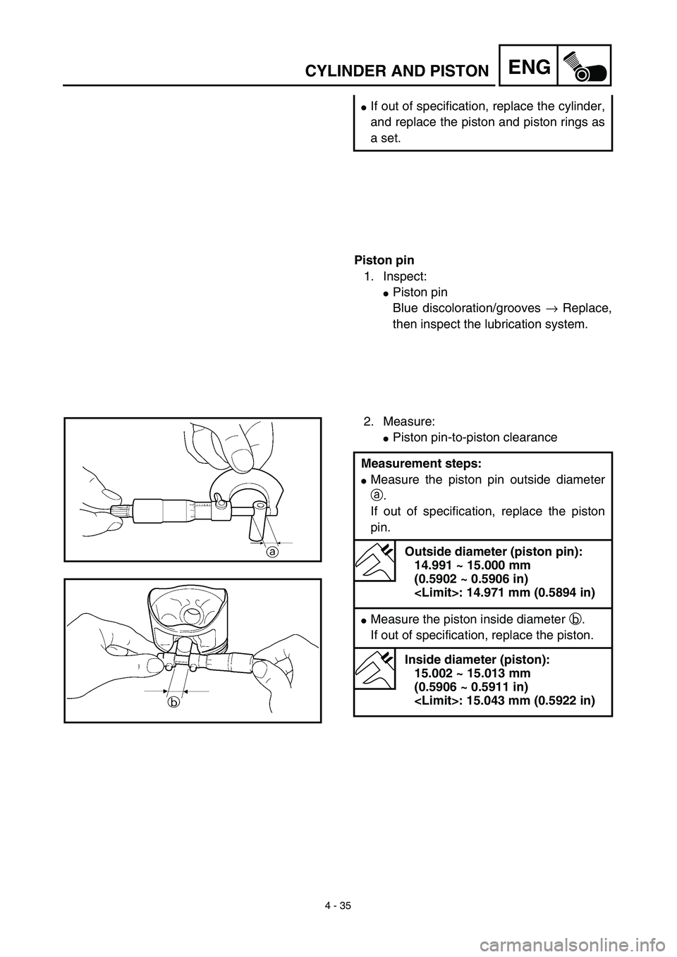
2. Measure:
�Piston pin-to-piston clearance
Measurement steps:
�Measure the piston pin outside diameter
a.
If out of specification, replace the piston
pin.
Outside diameter (piston pin):
14.991 ~ 15.000 mm
(0.5902 ~ 0.5906 in)
: 14.971 mm (0.5894 in)
�Measure the piston inside diameter b.
If out of specification, replace the piston.
Inside diameter (piston):
15.002 ~ 15.013 mm
(0.5906 ~ 0.5911 in)
: 15.043 mm (0.5922 in)
Page 282 of 510
4 - 37
ENGCYLINDER AND PISTON
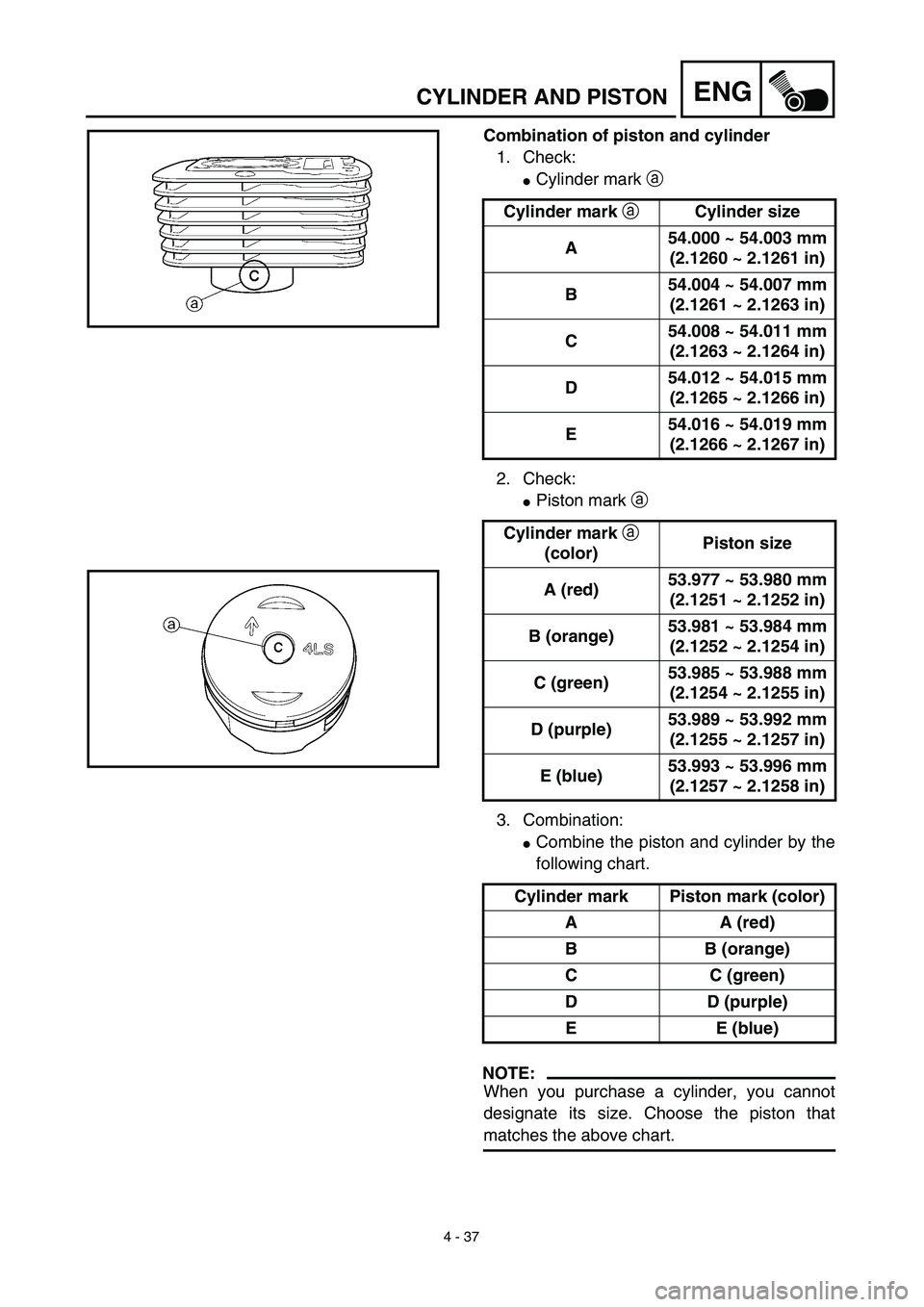
Combination of piston and cylinder
1. Check:
�Cylinder mark a
2. Check:
�Piston mark a
3. Combination:
�Combine the piston and cylinder by the
following chart.
NOTE:
When you purchase a cylinder, you cannot
designate its size. Choose the piston that
matches the above chart.Cylinder mark aCylinder size
A54.000 ~ 54.003 mm
(2.1260 ~ 2.1261 in)
B54.004 ~ 54.007 mm
(2.1261 ~ 2.1263 in)
C54.008 ~ 54.011 mm
(2.1263 ~ 2.1264 in)
D54.012 ~ 54.015 mm
(2.1265 ~ 2.1266 in)
E54.016 ~ 54.019 mm
(2.1266 ~ 2.1267 in)
Cylinder mark a
(color)Piston size
A (red)53.977 ~ 53.980 mm
(2.1251 ~ 2.1252 in)
B (orange)53.981 ~ 53.984 mm
(2.1252 ~ 2.1254 in)
C (green)53.985 ~ 53.988 mm
(2.1254 ~ 2.1255 in)
D (purple)53.989 ~ 53.992 mm
(2.1255 ~ 2.1257 in)
E (blue)53.993 ~ 53.996 mm
(2.1257 ~ 2.1258 in)
Cylinder mark Piston mark (color)
A A (red)
B B (orange)
C C (green)
D D (purple)
E E (blue)
Page 496 of 510
6 - 1
–+ELEC
* The illustration shows the TT-R125LW
ELECTRICAL COMPONENTS AND WIRING DIAGRAM
EC600000
ELECTRICAL
EC610000
ELECTRICAL COMPONENTS AND WIRING DIAGRAM
EC611000
ELECTRICAL COMPONENTS
1CDI unit
2Engine stop switch
3Ignition coil
4CDI magneto
5Spark plugCOLOR CODE
B...................... Black
Br .................... Brown
G ..................... Green
O ..................... Orange
R ..................... Red
W..................... WhiteB/R .................. Black/Red
B/W ................. Black/White
G/L .................. Green/Blue
G/W ................. Green/White
W/L .................. White/Blue
W/R ................. White/Red
EC612000
WIRING DIAGRAM
 6 - 1
–+ELEC
* The illustration shows the TT-R125LW
ELECTRICAL COMPONENTS AND WIRING DIAGRAM
EC600000
ELECTRICAL
EC610000
ELECTRICAL COMPONENTS AND WIRING DIAGRAM
EC611000
ELECTRICAL COMPONENTS
1CDI")