Page 1607 of 2234
700TJ±01
B56435
Slide
B61414
Slide
B66957
Butyl TapeMirror Base
a
b
c
d
70±64
±
WINDSHIELD/WINDOWGLASS/MIRROR INNER REAR VIEW MIRROR ASSY
AVENSIS REPAIR MANUAL (RM1018E)
INNER REAR VIEW MIRROR ASSY
REPLACEMENT
HINT:
The installation is in the reverse order of the removal. However, when there is a special point concerning
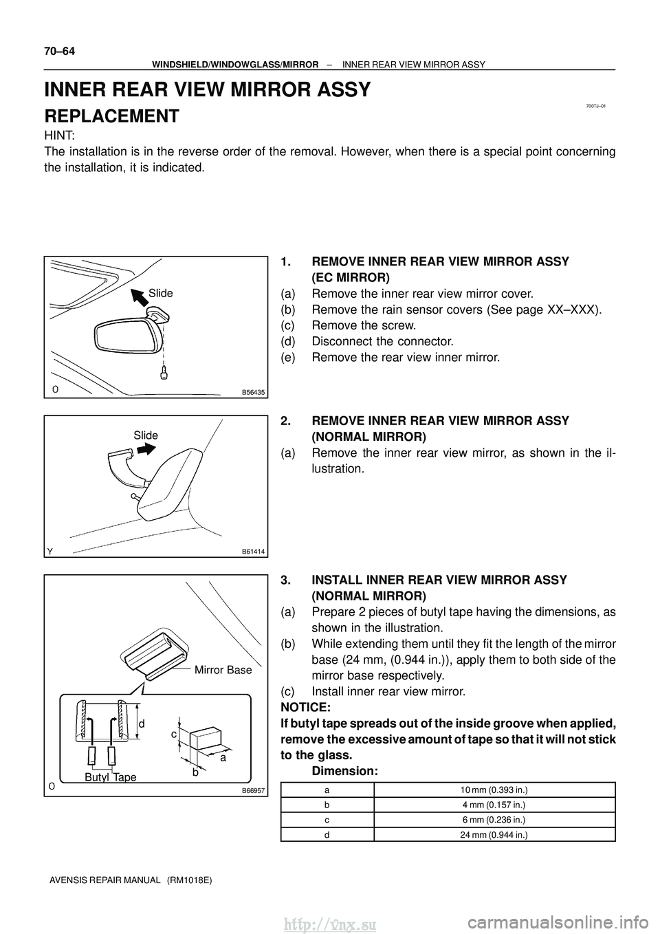
the installation, it is indicated. 1. REMOVE INNER REAR VIEW MIRROR ASSY(EC MIRROR)
(a) Remove the inner rear view mirror cover.
(b) Remove the rain sensor covers (See page XX±XXX).
(c) Remove the screw.
(d) Disconnect the connector.
(e) Remove the rear view inner mirror.
2. REMOVE INNER REAR VIEW MIRROR ASSY (NORMAL MIRROR)
(a) Remove the inner rear view mirror, as shown in the il- lustration.
3. INSTALL INNER REAR VIEW MIRROR ASSY (NORMAL MIRROR)
(a) Prepare 2 pieces of butyl tape having the dimensions, as
shown in the illustration.
(b) While extending them until they fit the length of the mirror base (24 mm, (0.944 in.)), apply them to both side of the
mirror base respectively.
(c) Install inner rear view mirror.
NOTICE:
If butyl tape spreads out of the inside groove when applied,
remove the excessive amount of tape so that it will not stick
to the glass. Dimension:
a10 mm (0.393 in.)
b4 mm (0.157 in.)
c6 mm (0.236 in.)
d24 mm (0.944 in.)
http://vnx.su
Page 1608 of 2234
700TI±01
B68929
B68929
±
WINDSHIELD/WINDOWGLASS/MIRROR OUTER REAR VIEW MIRROR ASSY LH
70±65
AVENSIS REPAIR MANUAL (RM1018E)
OUTER REAR VIEW MIRROR ASSY LH
REPLACEMENT
HINT:
�The installation is in the reverse order of the removal. However, when there is a special point concern-
ing the installation, it is indicated.
�Use the same procedures on the RH side as on the LH side.
1.REMOVE FRONT DOOR HOLE COVER SUB±ASSY NO.1 LH (See page 75±8)
(a) Remove the front door lower frame bracket garnish.
(b) Remove the front door trim base.
(c) Only driver side: Remove the fuel lid opener switch.
(d) w/ Power window: Remove the power window regulator switch.
(e) Remove the front door trim board sub.
(f) Remove the front door inside handle.
(g) remove the front service hole cover No. 1.
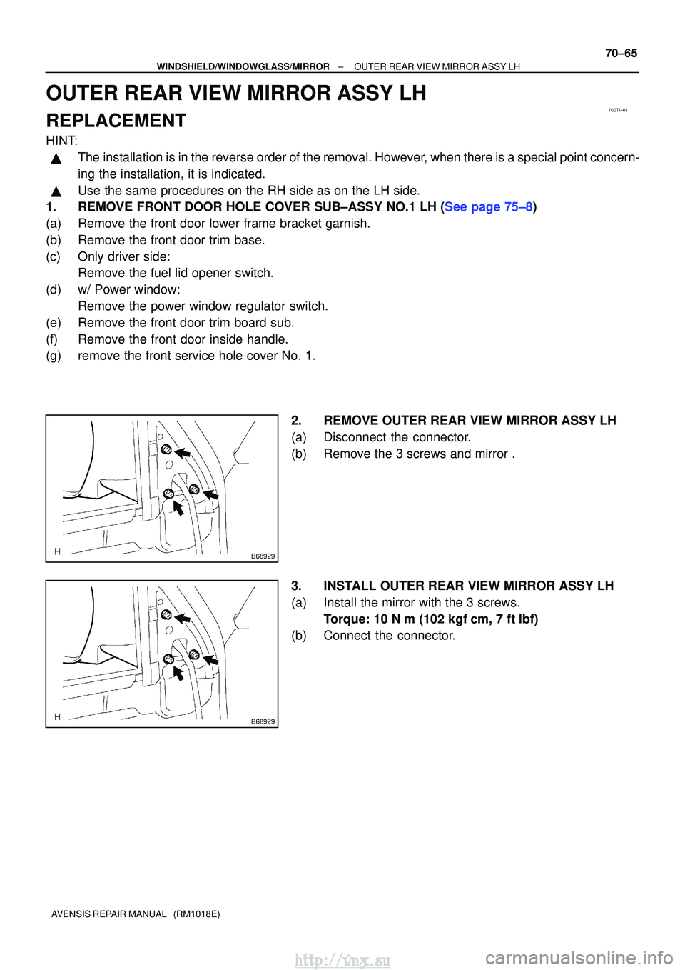
2. REMOVE OUTER REAR VIEW MIRROR ASSY LH
(a) Disconnect the connector.
(b) Remove the 3 screws and mirror .
3. INSTALL OUTER REAR VIEW MIRROR ASSY LH
(a) Install the mirror with the 3 screws.Torque: 10 N �m (102 kgf� cm, 7 ft�lbf)
(b) Connect the connector.
http://vnx.su
Page 1609 of 2234
700TE±01
B54715
Switch
Position(A) (B)
Retract ed
Position Driving
Position
B54716
Switch
Position
(A) (B)
Forward
Position
Retract ed
Position
(3)
Retracted
PositionDriving
Position
(4)
B54717
Switch
Position
(A) (B)
Retract ed
Position Driving
Position
Retract ed
Position
(1)
(3)
±
WINDSHIELD/WINDOWGLASS/MIRROR POWER MIRROR CONTROL SYSTEM
70±55
AVENSIS REPAIR MANUAL (RM1018E)
POWER MIRROR CONTROL SYSTEM
ON±VEHICLE INSPECTION
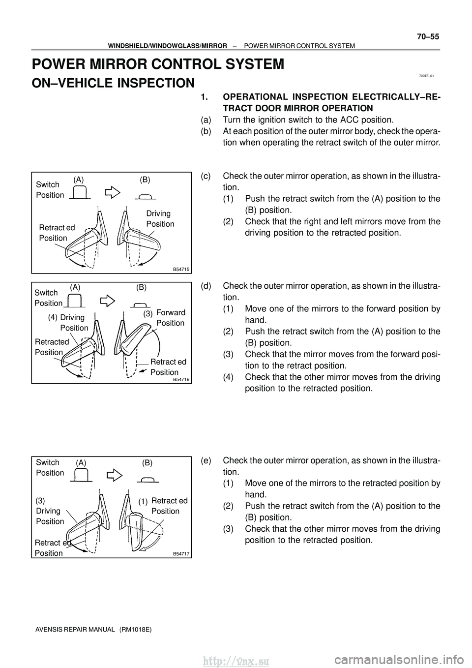
1. OPERATIONAL INSPECTION ELECTRICALLY±RE-
TRACT DOOR MIRROR OPERATION
(a) Turn the ignition switch to the ACC position.
(b) At each position of the outer mirror body, check the opera- tion when operating the retract switch of the outer mirror.
(c) Check the outer mirror operation, as shown in the illustra- tion.
(1) Push the retract switch from the (A) position to the
(B) position.
(2) Check that the right and left mirrors move from the driving position to the retracted position.
(d) Check the outer mirror operation, as shown in the illustra- tion.
(1) Move one of the mirrors to the forward position byhand.
(2) Push the retract switch from the (A) position to the
(B) position.
(3) Check that the mirror moves from the forward posi- tion to the retract position.
(4) Check that the other mirror moves from the driving position to the retracted position.
(e) Check the outer mirror operation, as shown in the illustra- tion.
(1) Move one of the mirrors to the retracted position byhand.
(2) Push the retract switch from the (A) position to the (B) position.
(3) Check that the other mirror moves from the driving position to the retracted position.
http://vnx.su
Page 1610 of 2234
B54718
Switch
Position(A)
(B)
Retract ed
Position
Driving
Position
B54719
Switch
Position
(A)
(B)
Retracted
Position Driving
Position
Driving
Position
(3)
(1)
70±56
±
WINDSHIELD/WINDOWGLASS/MIRROR POWER MIRROR CONTROL SYSTEM
AVENSIS REPAIR MANUAL (RM1018E)
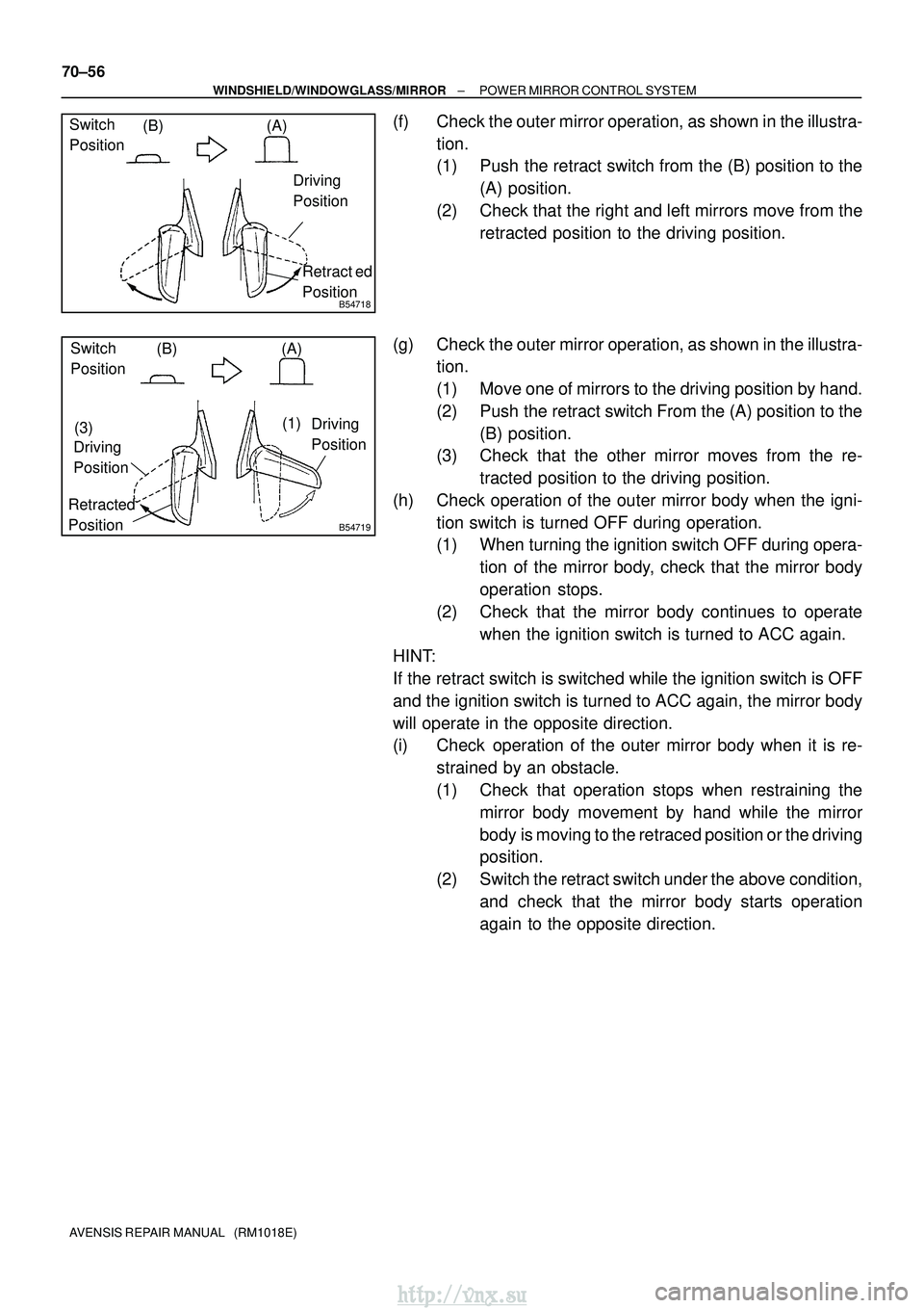
(f) Check the outer mirror operation, as shown in the illustra- tion.
(1) Push the retract switch from the (B) position to the(A) position.
(2) Check that the right and left mirrors move from the retracted position to the driving position.
(g) Check the outer mirror operation, as shown in the illustra- tion.
(1) Move one of mirrors to the driving position by hand.
(2) Push the retract switch From the (A) position to the
(B) position.
(3) Check that the other mirror moves from the re-
tracted position to the driving position.
(h) Check operation of the outer mirror body when the igni- tion switch is turned OFF during operation.
(1) When turning the ignition switch OFF during opera-tion of the mirror body, check that the mirror body
operation stops.
(2) Check that the mirror body continues to operate when the ignition switch is turned to ACC again.
HINT:
If the retract switch is switched while the ignition switch is OFF
and the ignition switch is turned to ACC again, the mirror body
will operate in the opposite direction.
(i) Check operation of the outer mirror body when it is re-
strained by an obstacle.
(1) Check that operation stops when restraining themirror body movement by hand while the mirror
body is moving to the retraced position or the driving
position.
(2) Switch the retract switch under the above condition, and check that the mirror body starts operation
again to the opposite direction.
http://vnx.su
Page 1611 of 2234
700TF±01
B67247
Outer Rear View Mirror Assy LHOuter Mirror Switch Assy Outer Rear View Mirror Assy RH
±
WINDSHIELD/WINDOWGLASS/MIRROR POWER MIRROR CONTROL SYSTEM
70±57
AVENSIS REPAIR MANUAL (RM1018E)
LOCATION
http://vnx.su
Page 1612 of 2234
700TG±01
70±58
±
WINDSHIELD/WINDOWGLASS/MIRROR POWER MIRROR CONTROL SYSTEM
AVENSIS REPAIR MANUAL (RM1018E)
PROBLEM SYMPTOMS TABLE
SymptomSuspected AreaSee Page
Mirror does not operate
1. Outer mirror switch assy
2. Outer rear view mirror assy
3. Wire harness70±59
70±59 ±
Mirror operates abnormally
1. Outer mirror switch assy
2. Outer rear view mirror assy
3. Wire harness70±59
70±59±
http://vnx.su
Page 1613 of 2234
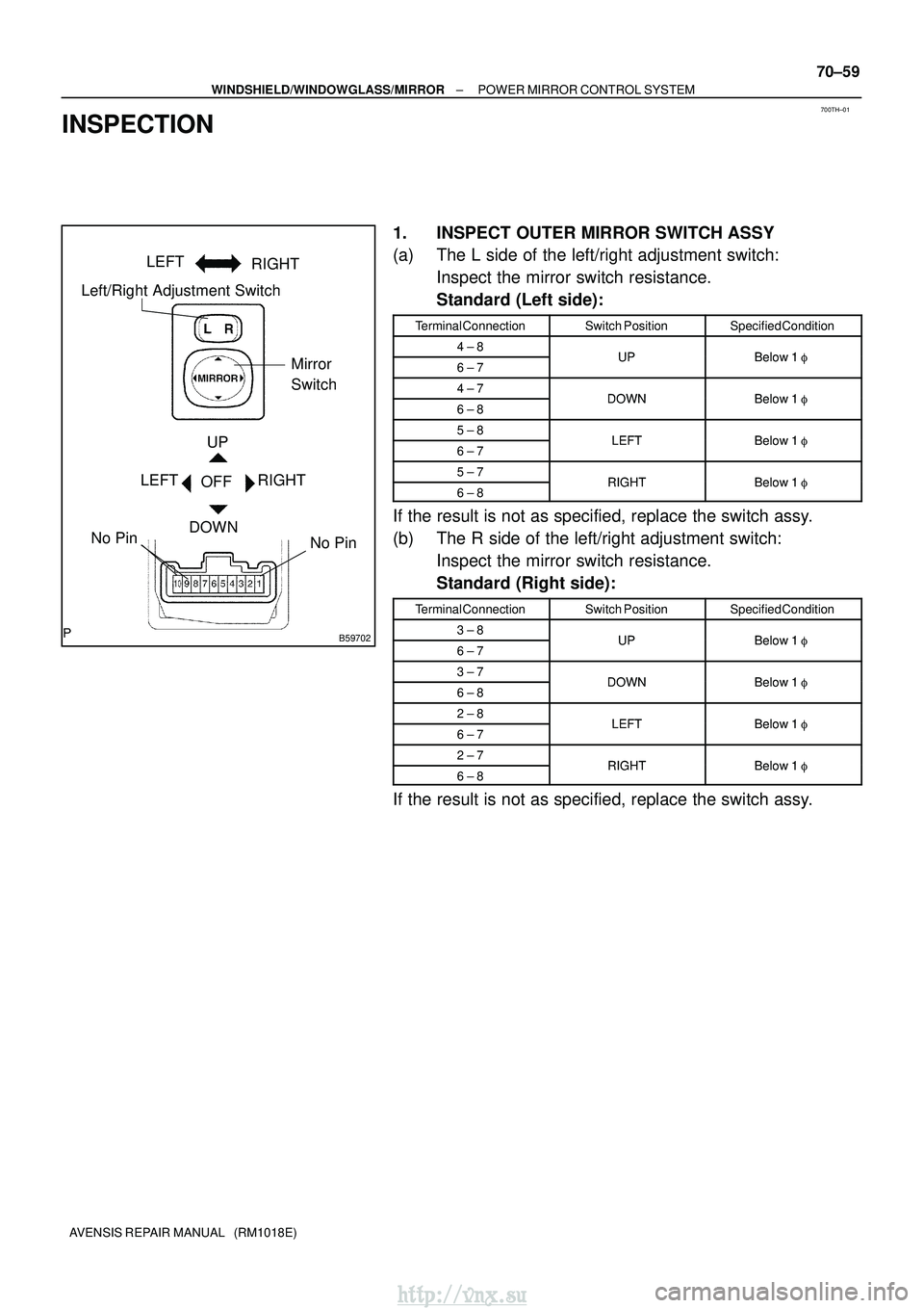
700TH±01
B59702
Left/Right Adjustment SwitchMirror
Switch
No Pin
UP
OFF
DOWN
LEFT RIGHT LEFT
RIGHT
No Pin
±
WINDSHIELD/WINDOWGLASS/MIRROR POWER MIRROR CONTROL SYSTEM
70±59
AVENSIS REPAIR MANUAL (RM1018E)
INSPECTION
1. INSPECT OUTER MIRROR SWITCH ASSY
(a) The L side of the left/right adjustment switch:
Inspect the mirror switch resistance.
Standard (Left side):
Terminal ConnectionSwitch PositionSpecified Condition
4 ± 8UPBelow 1 �6 ± 7UPBelow 1 �
4 ± 7DOWNBelow 1�6 ± 8DOWNBelow 1 �
5 ± 8LEFTBelow 1�6 ± 7LEFTBelow 1 �
5 ± 7RIGHTBelow 1�6 ± 8RIGHTBelow 1 �
If the result is not as specified, replace the switch assy.
(b) The R side of the left/right adjustment switch:
Inspect the mirror switch resistance.
Standard (Right side):
Terminal ConnectionSwitch PositionSpecified Condition
3 ± 8UPBelow 1 �6 ± 7UPBelow 1 �
3 ± 7DOWNBelow 1�6 ± 8DOWNBelow 1 �
2 ± 8LEFTBelow 1�6 ± 7LEFTBelow 1 �
2 ± 7RIGHTBelow 1�6 ± 8RIGHTBelow 1 �
If the result is not as specified, replace the switch assy.
http://vnx.su
Page 1614 of 2234
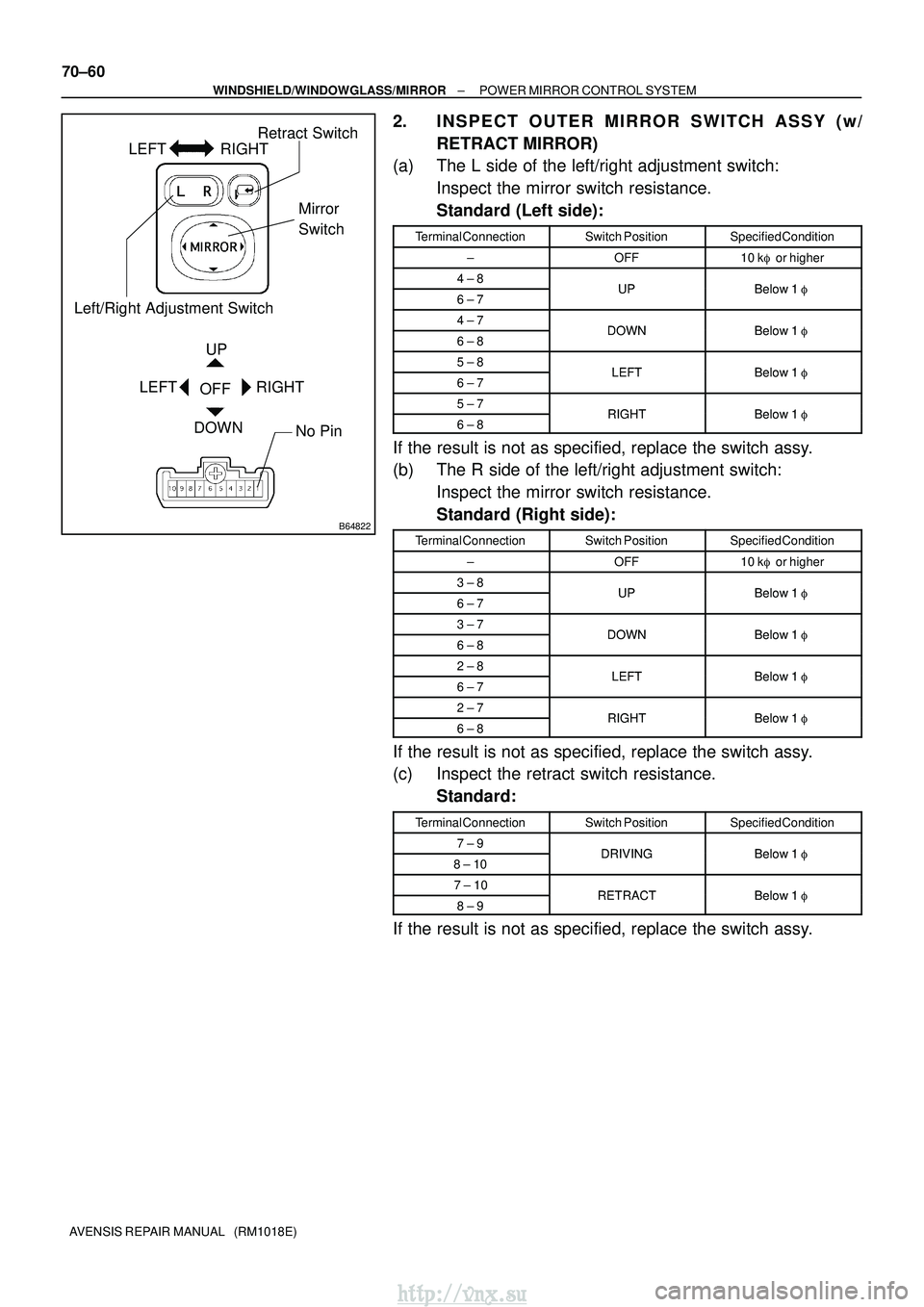
B64822
Left/Right Adjustment SwitchRetract Switch
Mirror
Switch
No Pin
UP
OFF
DOWN
LEFT RIGHT
LEFT RIGHT
70±60
±
WINDSHIELD/WINDOWGLASS/MIRROR POWER MIRROR CONTROL SYSTEM
AVENSIS REPAIR MANUAL (RM1018E)
2. INSPECT OUTER MIRROR SWITCH ASSY (w/ RETRACT MIRROR)
(a) The L side of the left/right adjustment switch:
Inspect the mirror switch resistance.
Standard (Left side):
Terminal ConnectionSwitch PositionSpecified Condition
±OFF10 k� or higher
4 ± 8UPBelow 1 �6 ± 7UPBelow 1 �
4 ± 7DOWNBelow 1�6 ± 8DOWNBelow 1 �
5 ± 8LEFTBelow 1�6 ± 7LEFTBelow 1 �
5 ± 7RIGHTBelow 1�6 ± 8RIGHTBelow 1 �
If the result is not as specified, replace the switch assy.
(b) The R side of the left/right adjustment switch:
Inspect the mirror switch resistance.
Standard (Right side):
Terminal ConnectionSwitch PositionSpecified Condition
±OFF10 k� or higher
3 ± 8UPBelow 1 �6 ± 7UPBelow 1 �
3 ± 7DOWNBelow 1�6 ± 8DOWNBelow 1 �
2 ± 8LEFTBelow 1�6 ± 7LEFTBelow 1 �
2 ± 7RIGHTBelow 1�6 ± 8RIGHTBelow 1 �
If the result is not as specified, replace the switch assy.
(c) Inspect the retract switch resistance.
Standard:
Terminal ConnectionSwitch PositionSpecified Condition
7 ± 9DRIVINGBelow 1 �8 ± 10DRIVINGBelow 1 �
7 ± 10RETRACTBelow 1�8 ± 9RETRACTBelow 1 �
If the result is not as specified, replace the switch assy.
http://vnx.su