Page 318 of 2234

A77913
Turn
Push
A77914
Turn
A81621
Fuel Pipe
Clamp
Push
11±28
±
FUELFUEL INJECTOR ASSY(1AZ±FE)
AVENSIS REPAIR MANUAL (RM1018E)
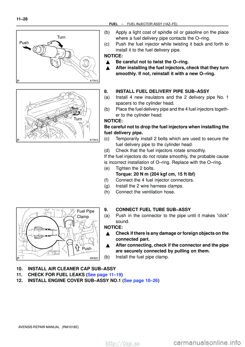
(b)Apply a light coat of spindle oil or gasoline on the place where a fuel delivery pipe contacts the O±ring.
(c)Push the fuel injector while twisting it back and forth to
install it to the fuel delivery pipe.
NOTICE:
�Be careful not to twist the O±ring.
�After installing the fuel injectors, check that they turn
smoothly. If not, reinstall it with a new O±ring.
8.INSTALL FUEL DELIVERY PIPE SUB±ASSY
(a)Install 4 new insulators and the 2 delivery pipe No. 1 spacers to the cylinder head.
(b)Place the fuel delivery pipe and the 4 fuel injectors togeth- er to the cylinder head.
NOTICE:
Be careful not to drop the fuel injectors when installing the
fuel delivery pipe.
(c)Temporarily install 2 bolts which are used to secure the fuel delivery pipe to the cylinder head.
(d)Check that the fuel injectors rotate smoothly.
If the fuel injectors do not rotate smoothly, the probable cause
is incorrect installation of O±ring. Replace with the O±ring.
(e)Tighten the 2 bolts. Torque: 20 N �m (204 kgf�cm, 15 ft�lbf)
(f)Connect the 4 fuel injector connectors.
(g)Install the 2 wire harness clamps.
(h)Connect the ventilation hose.
9.CONNECT FUEL TUBE SUB±ASSY
(a)Push in the connector to the pipe until it makes ºclickº sound.
NOTICE:
�Check if there is any damage or foreign objects on the
connected part.
�After connecting, check if the connector and the pipe
are securely connected by pulling on them.
(b)Install the fuel pipe clamp.
10.INSTALL AIR CLEANER CAP SUB±ASSY
11.CHECK FOR FUEL LEAKS (See page 11±19)
12.INSTALL ENGINE COVER SUB±ASSY NO.1 (See page 10±26)
http://vnx.su
Page 321 of 2234
A79577
N´m (kgf´cm, ft´lbf): Specified torque
� Non±reusable part �
Gasket �
Gasket Fuel Tube Sub±assy
Fuel Pipe Clamp
Fuel Pressure Pulsation
Damper Assy
Fuel Pump Assy
� Fuel Pump
Insulator
Fuel HoseFuel Pipe Sub±assy No. 1
� Fuel Injector Back±up Ring No. 1
25 (255, 18)
33 (331, 24)
9.0 (92, 80 in. �lbf)
38 (388, 28 )
30 (306, 22)
� Fuel Injector Back±up Ring No. 2
� Fuel Injector Back±up Ring No. 3
�
O±ring
Engine Cover Bracket
±
FUEL FUEL INJECTOR ASSY (1AZ±FSE)
11±39
AVENSIS REPAIR MANUAL (RM1018E)
http://vnx.su
Page 322 of 2234
A79597
N´m (kgf´cm, ft´lbf): Specified torque
� Non±reusable part �
Gasket �
Gasket
38 (388, 28)
21 (210, 15)
9.5 (97, 84 in. �lbf)
30 (306, 22)
9.8 (100, 7)
30 (306, 22)
30 (306, 22)
Union to Connector
Tube Hose
Vacuum Hose
Intake Manifold
Insulator No. 1
Intake Air Control Valve Assy
Intake Manifold Insulator No. 2
Surge Tank
Stay No. 1
Engine Cover Bracket Charcoal Canister Assy
Intake Manifold
x2
11±40
±
FUEL FUEL INJECTOR ASSY (1AZ±FSE)
AVENSIS REPAIR MANUAL (RM1018E)
http://vnx.su
Page 324 of 2234
110TY±01
A78470
� Fuel Injector O±Ring
� Non±reusable part
N´m (kgf´cm, ft´lbf) : Specified torque
7.0 (71, 62 in.´lbf)
Ventilation Hose
Fuel Injector Connector
No. 1 Spacer
�
Injector Vibration
Insulator Fuel Delivery Pipe
Sub±assy
Fuel Tube Sub±assy
Fuel Pipe Clamp No. 2
Cylinder Head Cover No. 2
�
Fuel Injector O±Ring
� Fuel Injector Grommet
Fuel Injector Assy
Fuel Injector Assy
1ZZ±FE:
Clip
3ZZ±FE:
19 (189, 14)
9.0 (91, 80 in.´lbf)
11±10
±
FUEL FUEL INJECTOR ASSY (1ZZ±FE/3ZZ±FE)
AVENSIS REPAIR MANUAL (RM1018E)
FUEL INJECTOR ASSY (1ZZ±FE/3ZZ±FE)
COMPONENTS
http://vnx.su
Page 326 of 2234
A78473
(a)(a)
(a)
(a)
(b)
(b)
(b)
A78480
A78475
Delivery Pipe No. 1 spacer
Insulator
A78476
11±12
±
FUEL FUEL INJECTOR ASSY (1ZZ±FE/3ZZ±FE)
AVENSIS REPAIR MANUAL (RM1018E)
(b) Disconnect the 4 fuel injector connectors.
(c) Remove the 3 wire harness clamps.
(d) Remove the 3 bolts, and then remove the fuel delivery pipe together with the 4 fuel injectors.
NOTICE:
Be careful not to drop the fuel injectors when removing the
fuel delivery pipe.
(e) Remove the 2 delivery pipe No. 1 spacers and the 4 insu- lators from the cylinder head.
5. REMOVE FUEL INJECTOR ASSY
(a) Pull out the 4 fuel injectors from the fuel delivery pipe.
http://vnx.su
Page 327 of 2234

A78477
New O±ring
1ZZ±FE:
A78478
New O±ring
3ZZ±FE:
New Grommet
A78479
Turn
Push
A78474
Turn
A
A
B
±
FUEL FUEL INJECTOR ASSY (1ZZ±FE/3ZZ±FE)
11±13
AVENSIS REPAIR MANUAL (RM1018E)
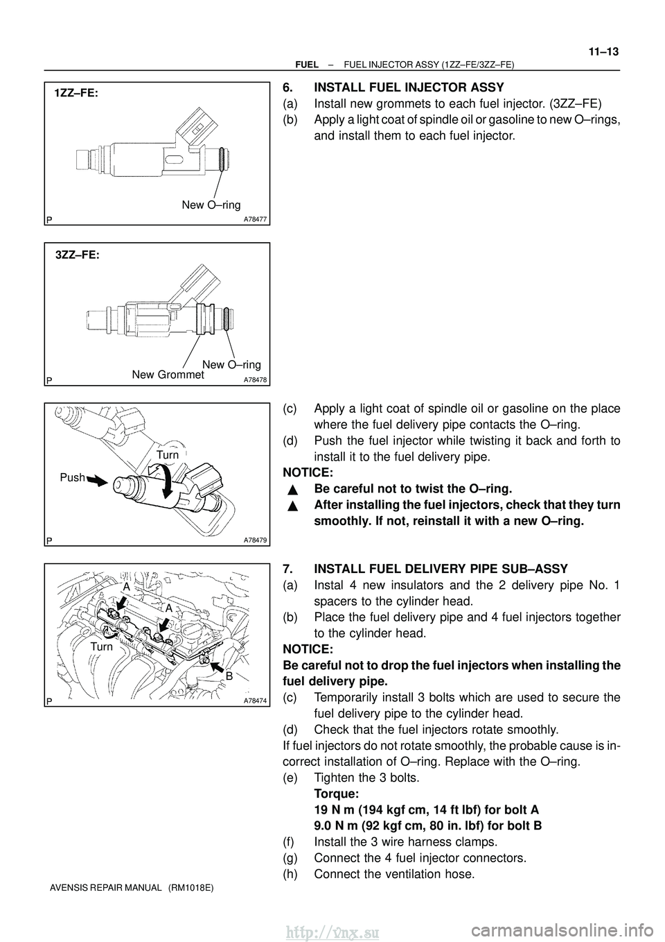
6. INSTALL FUEL INJECTOR ASSY
(a) Install new grommets to each fuel injector. (3ZZ±FE)
(b) Apply a light coat of spindle oil or gasoline to new O±rings,
and install them to each fuel injector.
(c) Apply a light coat of spindle oil or gasoline on the place where the fuel delivery pipe contacts the O±ring.
(d) Push the fuel injector while twisting it back and forth to install it to the fuel delivery pipe.
NOTICE:
�Be careful not to twist the O±ring.
�After installing the fuel injectors, check that they turn
smoothly. If not, reinstall it with a new O±ring.
7. INSTALL FUEL DELIVERY PIPE SUB±ASSY
(a) Instal 4 new insulators and the 2 delivery pipe No. 1 spacers to the cylinder head.
(b) Place the fuel delivery pipe and 4 fuel injectors together
to the cylinder head.
NOTICE:
Be careful not to drop the fuel injectors when installing the
fuel delivery pipe.
(c) Temporarily install 3 bolts which are used to secure the fuel delivery pipe to the cylinder head.
(d) Check that the fuel injectors rotate smoothly.
If fuel injectors do not rotate smoothly, the probable cause is in-
correct installation of O±ring. Replace with the O±ring.
(e) Tighten the 3 bolts. Torque:
19 N�m (194 kgf� cm, 14 ft�lbf) for bolt A
9.0 N� m (92 kgf �cm, 80 in. �lbf) for bolt B
(f) Install the 3 wire harness clamps.
(g) Connect the 4 fuel injector connectors.
(h) Connect the ventilation hose.
http://vnx.su
Page 332 of 2234
A79577
N´m (kgf´cm, ft´lbf): Specified torque
� Non±reusable part �
Gasket �
Gasket Fuel Tube Sub±assy
Fuel Pipe Clamp
Fuel Pressure Pulsation
Damper Assy
Fuel Pump Assy
� Fuel Pump
Insulator
Fuel HoseFuel pipe Sub±assy No. 1
� Fuel Injector Back±up Ring No. 1
25 (255, 18)
33 (331, 24)
9.0 (92, 80 in. �lbf)
38 (388, 28 )
30 (306, 22)
� Fuel Injector Back±up Ring No. 2
� Fuel Injector Back±up Ring No. 3
�
O±ring
Engine Cover Bracket
±
FUEL FUEL PUMP ASSY (1AZ±FSE)
11±51
AVENSIS REPAIR MANUAL (RM1018E)
http://vnx.su
Page 334 of 2234

A79573
A79574
A79834
±
FUEL FUEL PUMP ASSY (1AZ±FSE)
11±53
AVENSIS REPAIR MANUAL (RM1018E)
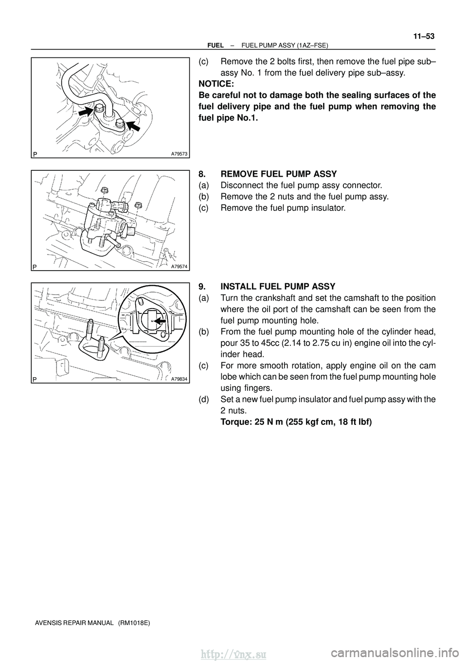
(c) Remove the 2 bolts first, then remove the fuel pipe sub±
assy No. 1 from the fuel delivery pipe sub±assy.
NOTICE:
Be careful not to damage both the sealing surfaces of the
fuel delivery pipe and the fuel pump when removing the
fuel pipe No.1.
8. REMOVE FUEL PUMP ASSY
(a) Disconnect the fuel pump assy connector.
(b) Remove the 2 nuts and the fuel pump assy.
(c) Remove the fuel pump insulator.
9. INSTALL FUEL PUMP ASSY
(a) Turn the crankshaft and set the camshaft to the position
where the oil port of the camshaft can be seen from the
fuel pump mounting hole.
(b) From the fuel pump mounting hole of the cylinder head,
pour 35 to 45cc (2.14 to 2.75 cu in) engine oil into the cyl-
inder head.
(c) For more smooth rotation, apply engine oil on the cam lobe which can be seen from the fuel pump mounting hole
using fingers.
(d) Set a new fuel pump insulator and fuel pump assy with the 2 nuts.
Torque: 25 N �m (255 kgf� cm, 18 ft�lbf)
http://vnx.su