Page 359 of 2234

O±ringDelivery Pipe
Injector CORRECT
WRONG
B10707
A75345
Delivery Pipe
Insulator Grommet
O±ring
Insulator
Delivery Pipe
O±ring
1ZZ±FE
3ZZ±FE
O±ring Retainer Pipe
Nylon Tube Housing
A50709
A75344
Fuel Pipe Clamp No.2
11±2
±
FUEL FUEL SYSTEM (1ZZ±FE/3ZZ±FE)
AVENSIS REPAIR MANUAL (RM1018E)
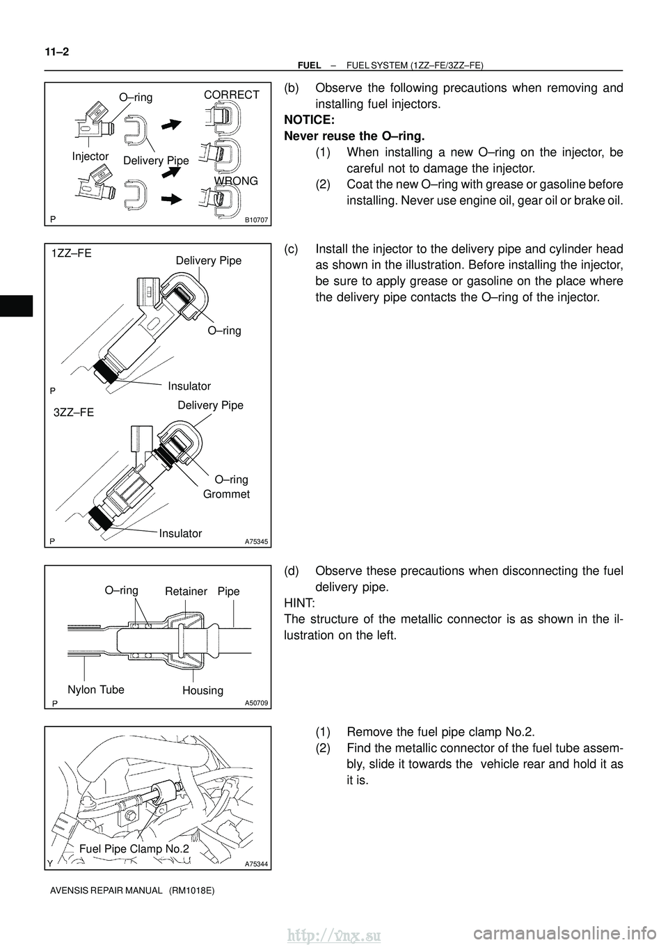
(b) Observe the following precautions when removing and installing fuel injectors.
NOTICE:
Never reuse the O±ring.
(1) When installing a new O±ring on the injector, becareful not to damage the injector.
(2) Coat the new O±ring with grease or gasoline before
installing. Never use engine oil, gear oil or brake oil.
(c) Install the injector to the delivery pipe and cylinder head as shown in the illustration. Before installing the injector,
be sure to apply grease or gasoline on the place where
the delivery pipe contacts the O±ring of the injector.
(d) Observe these precautions when disconnecting the fuel delivery pipe.
HINT:
The structure of the metallic connector is as shown in the il-
lustration on the left.
(1) Remove the fuel pipe clamp No.2.
(2) Find the metallic connector of the fuel tube assem-bly, slide it towards the vehicle rear and hold it as
it is.
http://vnx.su
Page 391 of 2234
110U9±01
A79435
Air Cleaner Cap w/ Hose
Air Cleaner Element
Air Cleaner Case
7.0 (71, 62 in.�lbf)
N´m (kgf´cm, ft´lbf)
: Specified torque
Radiator Hose Outlet
Clip
Engine Room Cover Side
Clip
Retainer
Radiator Support
Opening Cover
8.0 (82, 71 in.�lbf)
5.0 (51, 44 in.�lbf)
V (Cooler Compressor
to Crankshaft Pulley)
Belt No. 1
Injector Driver
72 (734, 53)
52 (530, 38)52 (530, 38)
Engine Cover No. 1
Engine Mounting Insulator Sub±assy RH
39 (398, 29)
Power Steering
Idle Pulley Bracket
52 (530, 38)
Clip
Engine Under Cover RH
Engine Under Cover Sub±assy No. 1
Clip
Radiator Reserve Tank Assy
6.0 (61, 53 in.� lbf)
11±66
±
FUEL INJECTION OR SUPPLY PUMP ASSY (1CD±FTV)
AVENSIS REPAIR MANUAL (RM1018E)
INJECTION OR SUPPLY PUMP ASSY (1CD±FTV)
COMPONENTS
http://vnx.su
Page 393 of 2234
A79436
5.0 (51, 44 in.�lbf)
* 42 (428, 31)
46 (469, 34)
* 31 (316, 23)
34 (347, 25)
* 31 (316, 23)
34 (347, 25)
Injection Pipe Clamp No. 2
Injection Pipe Sub±assy
� Fuel Inlet Pipe Sub±assy
64 (650, 47)
Injection Pump
Drive Pulley
� O±ring
Oil Level Gage Guide
: Specified torqueN´m (kgf´cm, ft´lbf)
* Use SST
18 (184, 13)
Oil Level Gage Sub±assy
Injection or
Supply Pump Assy
21 (210, 15)
21 (210, 15)
Water Inlet
8.8 (90, 78 in.�
lbf)
� Gasket
5.0 (51, 44 in.� lbf)
Intake Manifold
Insulator No. 1
* 42 (428, 31)
46 (469, 34)
Injection Pump to Fuel Filter
Fuel Hose or Pipe
Injection Pump to Fuel Pipe
Fuel Hose
11±68
±
FUEL INJECTION OR SUPPLY PUMP ASSY (1CD±FTV)
AVENSIS REPAIR MANUAL (RM1018E)
http://vnx.su
Page 394 of 2234

110UA±01
A15950
±
FUELINJECTION OR SUPPLY PUMP ASSY(1CD±FTV)
11±69
AVENSIS REPAIR MANUAL (RM1018E)
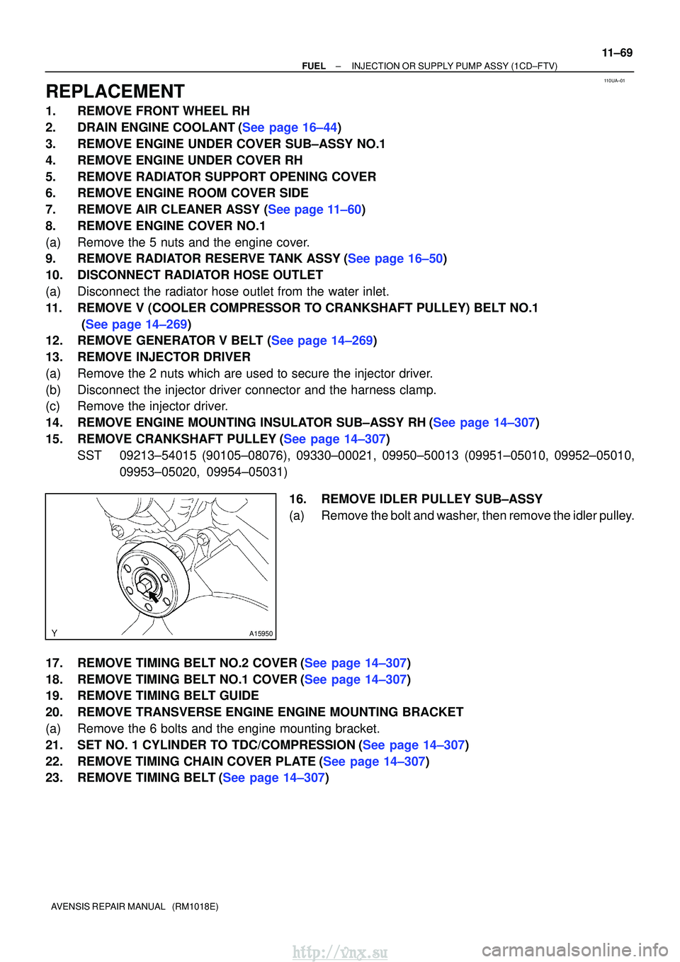
REPLACEMENT
1.REMOVE FRONT WHEEL RH
2.DRAIN ENGINE COOLANT(See page 16±44)
3.REMOVE ENGINE UNDER COVER SUB±ASSY NO.1
4.REMOVE ENGINE UNDER COVER RH
5.REMOVE RADIATOR SUPPORT OPENING COVER
6.REMOVE ENGINE ROOM COVER SIDE
7.REMOVE AIR CLEANER ASSY (See page 11±60)
8.REMOVE ENGINE COVER NO.1
(a)Remove the 5 nuts and the engine cover.
9.REMOVE RADIATOR RESERVE TANK ASSY(See page 16±50)
10.DISCONNECT RADIATOR HOSE OUTLET
(a)Disconnect the radiator hose outlet from the water inlet.
11.REMOVE V (COOLER COMPRESSOR TO CRANKSHAFT PULLEY) BELT NO.1
(See page 14±269)
12.REMOVE GENERATOR V BELT (See page 14±269)
13.REMOVE INJECTOR DRIVER
(a)Remove the 2 nuts which are used to secure the injector driver.
(b)Disconnect the injector driver connector and the harness clamp.
(c)Remove the injector driver.
14.REMOVE ENGINE MOUNTING INSULATOR SUB±ASSY RH(See page 14±307)
15.REMOVE CRANKSHAFT PULLEY(See page 14±307)
SST09213±54015 (90105±08076), 09330±00021, 09950±50013 (0995\
1±05010, 09952±05010, 09953±05020, 09954±05031)
16.REMOVE IDLER PULLEY SUB±ASSY
(a)Remove the bolt and washer, then remove the idler pulley.
17.REMOVE TIMING BELT NO.2 COVER(See page 14±307)
18.REMOVE TIMING BELT NO.1 COVER(See page 14±307)
19. REMOVE TIMING BELT GUIDE
20. REMOVE TRANSVERSE ENGINE ENGINE MOUNTING BRACKET
(a) Remove the 6 bolts and the engine mounting bracket.
21.SET NO. 1 CYLINDER TO TDC/COMPRESSION(See page 14±307)
22.REMOVE TIMING CHAIN COVER PLATE(See page 14±307)
23.REMOVE TIMING BELT(See page 14±307)
http://vnx.su
Page 396 of 2234
A79150
A79151
A79152
A62166
SST
±
FUELINJECTION OR SUPPLY PUMP ASSY(1CD±FTV)
11±71
AVENSIS REPAIR MANUAL (RM1018E)
29.REMOVE INTAKE MANIFOLD INSULATOR NO.1
(a)Remove the 2 bolts and the intake manifold insulator.
30.REMOVE OIL LEVEL GAGE SUB±ASSY
31.REMOVE OIL LEVEL GAGE GUIDE(See page 17±22)
32.REMOVE WATER INLET(See page 16±50) 33. DISCONNECT INJECTION PUMP TO FUEL PIPE FUELHOSE
(a) Disconnect the injection pump to fuel pipe fuel hose from the supply pump.
34. DISCONNECT INJECTION PUMP TO FUEL FILTER FUEL HOSE OR PIPE
(a) Disconnect the injection pump to fuel filter fuel hose or pipe from the supply pump.
35. REMOVE INJECTION PUMP DRIVE PULLEY
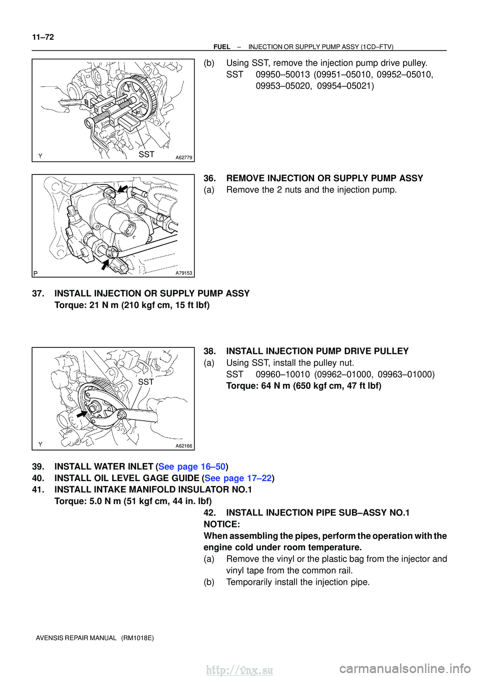
(a) Using SST, remove the pulley nut. SST 09960±10010 (09962±01000, 09963±01000)
http://vnx.su
Page 397 of 2234

A62779SST
A79153
A62166
SST
11±72
±
FUELINJECTION OR SUPPLY PUMP ASSY(1CD±FTV)
AVENSIS REPAIR MANUAL (RM1018E)
(b)Using SST, remove the injection pump drive pulley. SST09950±50013 (09951±05010, 09952±05010, 09953±05020, 09954±05021)
36.REMOVE INJECTION OR SUPPLY PUMP ASSY
(a)Remove the 2 nuts and the injection pump.
37.INSTALL INJECTION OR SUPPLY PUMP ASSY Torque: 21 N �m (210 kgf�cm, 15 ft�lbf)
38.INSTALL INJECTION PUMP DRIVE PULLEY
(a)Using SST, install the pulley nut.SST09960±10010 (09962±01000, 09963±01000)
Torque: 64 N �m (650 kgf�cm, 47 ft�lbf)
39.INSTALL WATER INLET(See page 16±50)
40.INSTALL OIL LEVEL GAGE GUIDE(See page 17±22)
41. INSTALL INTAKE MANIFOLD INSULATOR NO.1 Torque: 5.0 N �m (51 kgf �cm, 44 in. �lbf)
42. INSTALL INJECTION PIPE SUB±ASSY NO.1
NOTICE:
When assembling the pipes, perform the operation with the
engine cold under room temperature.
(a) Remove the vinyl or the plastic bag from the injector and vinyl tape from the common rail.
(b) Temporarily install the injection pipe.
http://vnx.su
Page 400 of 2234

±
FUEL INJECTION OR SUPPLY PUMP ASSY (1CD±FTV)
11±75
AVENSIS REPAIR MANUAL (RM1018E)
52.INSTALL TIMING BELT GUIDE(See page 14±307)
53.INSTALL TIMING BELT NO.1 COVER(See page 14±307)
54.INSTALL TIMING BELT NO.2 COVER(See page 14±307)
55. INSTALL IDLER PULLEY SUB±ASSY
Torque: 40 N �m (408 kgf� cm, 30 ft�lbf)
56.INSTALL CRANKSHAFT PULLEY(See page 14±307) SST 09213±54015 (90105±08076), 09330±00021
57.INSTALL ENGINE MOUNTING INSULATOR SUB±ASSY RH(See page 14±307)
58. INSTALL INJECTOR DRIVER Torque: 5.0 N �m (51 kgf �cm, 44 in. �lbf)
59. ADJUST V (COOLER COMPRESSOR TO CRANKSHAFT PULLEY) BELT NO.1 (See page 14±269)
60.INSTALL RADIATOR RESERVE TANK ASSY(See page 16±50)
61. INSTALL ENGINE COVER NO.1 Torque: 8.0 N �m (82 kgf �cm, 71 in. �lbf)
62.INSTALL AIR CLEANER ASSY (See page 11±60)
63. INSTALL FRONT WHEEL RH
Torque: 103 N� m (1,050 kgf�cm, 76 ft �lbf)
64.ADD ENGINE COOLANT(See page 16±44)
65.CHECK FOR ENGINE COOLANT LEAKS(See page 16±37)
66.CHECK FOR FUEL LEAKS(See page 11±60)
http://vnx.su
Page 439 of 2234
A79441
N´m (kgf´cm, ft´lbf): Specified torque
� Non±reusable part �
Gasket
� Gasket
�
Gasket
20 (204, 15)
20 (204, 15)
20 (204, 15)
12 (122, 8.9)
53 (540, 39)
13 (135, 9.7)
36 (367, 27)
61 (622, 45)
56 (571, 41)
25 (255, 18)
Turbo Insulator No. 1
Exhaust Manifold Heat Insulator No. 2
Turbocharger Stay Turbocharger Sub±assy
Turbo Oil Inlet Pipe
Sub±assy
Manifold Stay
Manifold Stay No. 2
Exhaust Manifold
Converter Sub±assy
Turbo Insulator No. 2
Turbo Water Pipe
Sub±assy No. 1
13 (135, 9.7)
56 (571, 41)
Turbo Water
Hose No. 2
Turbo Water
Hose No. 1
� Gasket
12 (122, 8.9)
�
13±10
±
INTAKE TURBOCHARGER SUB±ASSY (1CD±FTV)
AVENSIS REPAIR MANUAL (RM1018E)
http://vnx.su