Page 555 of 2234
A77302
A77353
±
ENGINE MECHANICALCYLINDER HEAD GASKET(1AZ±FSE)
14±257
AVENSIS REPAIR MANUAL (RM1018E)
(e)Raise a clamp up, and slide it toward the air cleaner cap,
then remove the air cleaner cap from its case.
(f)Remove the air cleaner element.
(g)Remove the 4 bolts and the air cleaner case.
43.DISCONNECT RADIATOR HOSE INLET
44.DISCONNECT UNION TO CONNECTOR TUBE HOSE
45.DISCONNECT HEATER INLET WATER HOSE
46.SEPARATE FUEL TUBE SUB±ASSY
47.SEPARATE ENGINE WIRE
48.REMOVE THROTTLE BODY ASSY (See page 10±44)
49. REMOVE CHARCOAL CANISTER ASSY 50. REMOVE INTAKE MANIFOLD
(a) Remove the 5 bolts and 2 nuts.
(b) Disconnect the 2 vacuum hoses.
(c) Remove the 2 stud bolts.
(d) Remove the intake manifold and insulator.
51. REMOVE INTAKE AIR CONTROL VALVE ASSY
(a) Remove the intake air control valve and gasket.
52. REMOVE MANIFOLD CONVERTER INSULATOR NO.1
(a) Disconnect the oxygen sensor connector.
(b) Remove the 2 bolts and nut, and then remove the manifold insulator.
http://vnx.su
Page 556 of 2234
A77350
A52497
A32664
A56213
14±258
±
ENGINE MECHANICALCYLINDER HEAD GASKET(1AZ±FSE)
AVENSIS REPAIR MANUAL (RM1018E)
53.REMOVE EXHAUST MANIFOLD CONVERTER SUB±ASSY
(a)Remove the 2 bolts and 2 nuts, and then detach the No.
1 and No. 2 exhaust manifold stay.
(b)Disconnect the 3 oxygen sensor connectors.
(c)Remove the 5 nuts, the exhaust manifold and gasket.
54.REMOVE NO.2 CAMSHAFT (See page 14±240)
55.REMOVE CAMSHAFT (See page 14±240)
56. REMOVE CAMSHAFT TIMING OIL CONTROL VALVE ASSY
(a) Remove the bolt and the oil control valve. 57. REMOVE CAMSHAFT BEARING NO.2
58. SUPPORT ENGINE ASSEMBLY WITH TRANSAXLE
(a) Install the oil pan sub±assy.
(b) Set the jack under the engine assembly w/ transaxle, andplace a wooden block on the jack.
(c) Remove the chain block and sling devise.
http://vnx.su
Page 559 of 2234

14±261
AVENSIS REPAIR MANUAL (RM1018E)
67.IN STALL EXHAUST MANIFOLD CONVERTER
SUB±ASSY
(a)Install a new gasket and the exhau")
A77332
23
145
A77350
±
ENGINE MECHANICALCYLINDER HEAD GASKET(1AZ±FSE)
14±261
AVENSIS REPAIR MANUAL (RM1018E)
67.IN STALL EXHAUST MANIFOLD CONVERTER
SUB±ASSY
(a)Install a new gasket and the exhaust manifold with the 5
nuts.
Torque: 37 N �m (378 kgf�cm, 27 ft�lbf)
(b)Install the No. 1 and No. 2 exhaust manifold stays with the 2 bolts and 2 nuts.
Torque: 44 N �m (449 kgf�cm, 32 ft�lbf)
68.INSTALL EXHAUST MANIFOLD HEAT INSULATOR NO.1 Torque: 12 N �m (122 kgf�cm,9.0 ft�lbf)
69.INSTALL INTAKE AIR CONTROL VALVE ASSY
(a)Install a new gasket and the intake air control valve.
70.INSTALL INTAKE MANIFOLD
(a)Install the 2 stud bolts. Torque: 10 N �m (97 kgf�cm,84 in. �lbf)
(b)Install the intake manifold and insulator with the 5 bolts and 2 nuts. Torque: 30 N �m (306 kgf�cm,22 ft�lbf)
71.INSTALL THROTTLE BODY ASSY (See page 10±44)
72. INSTALL AIR CLEANER ASSEMBLY WITH HOSE Torque: 5.0 N �m (51 kgf �cm, 44 in. �lbf)
73. INSTALL CHAIN VIBRATION DAMPER NO.1 Torque: 9.0 N �m (92 kgf �cm, 80 in. �lbf)
74.INSTALL CHAIN SUB±ASSY (See page 14±222)
75. INSTALL TIMING CHAIN GUIDE Torque: 9.0 N �m (92 kgf �cm, 80 in. �lbf)
76. INSTALL CHAIN TENSIONER SLIPPER
Torque: 19 N �m (195 kgf� cm, 15 ft�lbf)
77.INSTALL CRANKSHAFT POSITION SENSOR PLATE NO.1 (See page 14±240)
78.INSTALL TIMING CHAIN OR BELT COVER SUB±ASSY (See page 14±222)
79.INSTALL V±RIBBED BELT TENSIONER ASSY (See page 14±222)
80.INSTALL OIL PAN SUB±ASSY (See page 14±222)
81.INSTALL CRANKSHAFT POSITION SENSOR (See page 18±17)
82.INSTALL CRANKSHAFT PULLEY (See page 14±222) SST 09213±54015 (91651±60855), 09330±00021
83.INSTALL CHAIN TENSIONER ASSY NO.1 (See page 14±222)
84. INSTALL TRANSVERSE ENGINE ENGINE MOUNTING INSULATOR
Torque: 52 N �m (530 kgf� cm, 38 ft�lbf)
85.INSTALL ENGINE MOUNTING BRACKET NO.2 RH (See page 14±222)
http://vnx.su
Page 563 of 2234
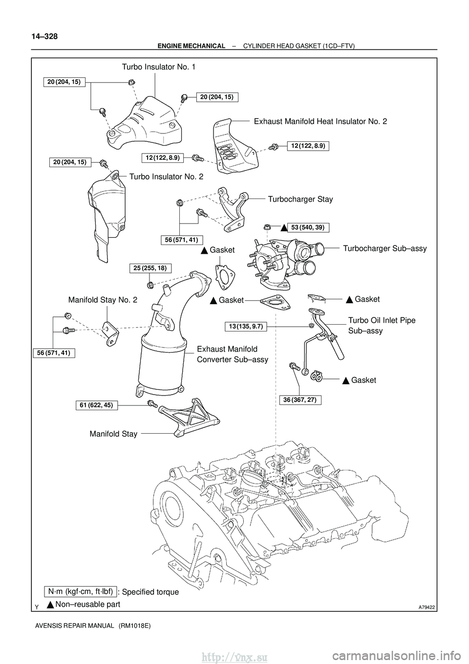
A79422
N´m (kgf´cm, ft´lbf): Specified torque
� Non±reusable part �
Gasket
� Gasket
�
Gasket
20 (204, 15)
20 (204, 15)
12 (122, 8.9)
53 (540, 39)
13 (135, 9.7)
36 (367, 27)61 (622, 45)
56 (571, 41)
25 (255, 18)
Turbo Insulator No. 1
Exhaust Manifold Heat Insulator No. 2
Turbocharger Stay Turbocharger Sub±assy
Turbo Oil Inlet Pipe
Sub±assy
Manifold Stay
Manifold Stay No. 2
Exhaust Manifold
Converter Sub±assy
Turbo Insulator No. 2
�
20 (204, 15)
12 (122, 8.9)
56 (571, 41)
�
Gasket
14±328
±
ENGINE MECHANICAL CYLINDER HEAD GASKET (1CD±FTV)
AVENSIS REPAIR MANUAL (RM1018E)
http://vnx.su
Page 568 of 2234

14±333
AVENSIS REPAIR MANUAL (RM1018E)
42.REMOVE EXHAUST MANIFOLD HEAT INSULATOR NO.2 (See page 13±11)
43.REMOVE MANIFOLD")
A79148
SST
A79143
SST
±
ENGINE MECHANICAL CYLINDER HEAD GASKET (1CD±FTV)
14±333
AVENSIS REPAIR MANUAL (RM1018E)
42.REMOVE EXHAUST MANIFOLD HEAT INSULATOR NO.2 (See page 13±11)
43.REMOVE MANIFOLD STAY NO.2 (See page 13±11)
44.REMOVE MANIFOLD STAY (See page 13±11)
45.REMOVE EXHAUST MANIFOLD CONVERTER SUB±ASSY (See page 13±11)
46.REMOVE TURBOCHARGER STAY (See page 13±11)
47.REMOVE TURBO WATER HOSE NO.1 (See page 13±11)
48.REMOVE TURBO WATER HOSE NO.2 (See page 13±11)
49.SEPARATE TURBO OIL INLET PIPE SUB±ASSY (See page 13±11)
50.REMOVE TURBOCHARGER SUB±ASSY (See page 13±11)
51.REMOVE CAMSHAFT POSITION SENSOR (See page 10±63)
52.REMOVE CAMSHAFT TIMING PULLEY (See page 14±318)
SST 09960±10010 (09962±01000, 09963±01000)
53. REMOVE FUEL INLET PIPE SUB±ASSY
(a) Using SST, remove the fuel inlet pipe from the commonrail side.
SST 09023±12700
(b) Using SST, remove the fuel inlet pipe from the pump side.
SST 09023±12700
NOTICE:
After removing the fuel pipe, cover the common rail and the
injector mounting holes with vinyl tape to prevent dust
from being introduced.
54. REMOVE INJECTION PIPE SUB±ASSY NO.1 (See page 11±60)
SST 09023±12700
(a) Remove the 2 nuts and 2 upper infection pipe clamps
from the intake manifold.
(b) Using SST, remove the injection pipe from the common rail side.
SST 09023±12700
(c) Using SST, remove the injection pipe from the injector
side.
SST 09023±12700
(d) After removing the fuel pipe, to prevent dust or foreign ob- jects from being introduced, cover the common rail with
vinyl tape and protect the injector inlet with a vinyl or a
plastic bag.
55. REMOVE INJECTION PIPE SUB±ASSY NO.2 SST 09023±12700
HINT:
Perform the same procedures as injection pipe No. 1.
56. REMOVE INJECTION PIPE SUB±ASSY NO.3
SST 09023±12700
HINT:
Perform the same procedures as injection pipe No. 1.
http://vnx.su
Page 575 of 2234

AVENSIS REPAIR MANUAL (RM1018E)
88.INSTALL FUEL INLET PIPE SUB±ASSY
NOTICE:
�In case of having the cylinder head gas")
A79148
SST
A79149
SST
14±340
±
ENGINE MECHANICALCYLINDER HEAD GASKET(1CD±FTV)
AVENSIS REPAIR MANUAL (RM1018E)
88.INSTALL FUEL INLET PIPE SUB±ASSY
NOTICE:
�In case of having the cylinder head gasket replaced,
must replace fuel inlet pipe, too.
�When assembling the pipe, perform the operation
with the engine cold under room temperature.
(a)Temporarily install the new fuel inlet pipe.
(b)Using SST, tighten the nut of the fuel inlet pipe to the com- mon rail side.
SST09023±12700
Torque:
42 N�m (428 kgf�cm, 31 ft�lbf) for a used pipe using SST
46 N�m (469 kgf�cm, 34 ft�lbf) for a used pipe not using
SST
31 N �m (316 kgf�cm, 23 ft�lbf) for a new pipe using SST
34 N�m (347 kgf �cm, 25 ft�lbf) for a new pipe not using
SST
HINT:
�Use a torque wrench with a fulcrum length of 30 cm
(11.81 in.)
�Check if the used pipe has deflection or is installed prop-
erly after inlet pipe is reassembled. If there is deflection
or if it can not be installed properly, replace the used pipe
with a new pipe.
(c)Using SST, tighten the nut of the fuel inlet pipe to the pump side.
SST09023±12700
Torque:
42 N�m (428 kgf�cm, 31 ft�lbf) for a used pipe using SST
46 N�m (469 kgf�cm, 34 ft�lbf) for a used pipe not using
SST
31 N �m (316 kgf�cm, 23 ft�lbf) for a new pipe using SST
34 N�m (347 kgf �cm, 25 ft�lbf) for a new pipe not using
SST
HINT:
�Use a torque wrench with a fulcrum length of 30 cm
(11.81 in.)
�Check if the used pipe has deflection or is installed prop-
erly after inlet pipe is reassembled. If there is deflection
or if it can not be installed properly, replace the used pipe
with a new pipe.
89.INSTALL TURBOCHARGER SUB±ASSY (See page 13±11)
90.INSTALL TURBO OIL INLET PIPE SUB±ASSY (See page 13±11)
91.INSTALL TURBOCHARGER STAY (See page 13±11)
92.INSTALL EXHAUST MANIFOLD CONVERTER SUB±ASSY (See page 13±11)
93.INSTALL MANIFOLD STAY NO.2 (See page 13±11)
94.INSTALL EXHAUST MANIFOLD HEAT INSULATOR NO.2 (See page 13±11)
http://vnx.su
Page 631 of 2234
A77317
Intake ManifoldIgnition Coil
Ventilation Hose No. 2 Ventilation Hose
Unleaded type:
Manifold Converter
Insulator No. 1
Intake Manifold Insulator
No. 1
V±ribbed Belt
Tensioner ASSY
Unleaded type:
Exhaust Manifold
Converter Sub±assy
Exhaust Manifold Stay Exhaust Manifold
Stay No. 2
Manifold Converter
Insulator No. 1
Exhaust Manifold
Converter Sub±assy
N´m (kgf´cm, ft´lbf): Specified torque
� Non±reusable part
9.0 (92, 80 in. �lbf)
� Gasket �
Gasket
12 (122, 9.0)
12 (122, 9.0)
37 (378, 27)
44 (449, 32)
44 (449, 32)
44 (449, 32)
� Gasket
Leaded type:
30 (306, 22)
30 (306, 22)
30 (306, 22)
12 (122, 9.0)
±
ENGINE MECHANICAL PARTIAL ENGINE ASSY (1AZ±FE)
14±119
AVENSIS REPAIR MANUAL (RM1018E)
http://vnx.su
Page 639 of 2234

14±127
AVENSIS REPAIR MANUAL (RM1018E)
63.SEPARATE VANE PUMP ASSY
(a)Disconnect the PS oil pressure switch connector.
(b)Remove the")
A77402SST
A56446
±
ENGINE MECHANICALPARTIAL ENGINE ASSY(1AZ±FE)
14±127
AVENSIS REPAIR MANUAL (RM1018E)
63.SEPARATE VANE PUMP ASSY
(a)Disconnect the PS oil pressure switch connector.
(b)Remove the 2 bolts and separate the vane pump from the engine.
64.REMOVE STARTER ASSY (See page 19±12)
65.REMOVE FRONT SUSPENSION CROSSMEMBER W/CENTER MEMBER
(a)Remove the through bolt and nut from the engine mounting insulator FR.
(b)Remove the through bolt and nut from the engine mounting insulator RR.
66.REMOVE FRONT DRIVE SHAFT ASSY LH (See page 30±6)
67.REMOVE FRONT DRIVE SHAFT ASSY RH (See page 30±6)
68.REMOVE MANUAL TRANSAXLE ASSY (M/T TRANSAXLE) (See page 41±24)
69.REMOVE AUTOMATIC TRANSAXLE ASSY (A/T TRANSAXLE) (See page 40±25)
70.REMOVE CLUTCH COVER ASSY (M/T TRANSAXLE) (See page 42±26)
71.REMOVE CLUTCH DISC ASSY (M/T TRANSAXLE) (See page 42±26)
72. REMOVE DRIVE PLATE AND RING GEAR ORFLYWHEEL
(a) Using SST, fix the crankshaft pulley and remove the drive plate and ring gear or flywheel.
SST 09213±54015 (91651±60855), 09330±00021
73. REMOVE CAMSHAFT TIMING OIL CONTROL VALVE ASSY (W/ VVT±i)
(a) Remove a bolt, O±ring and the camshaft timing oil control valve. 74. REMOVE INTAKE MANIFOLD
(a) Remove the 5 bolts and 2 nuts, and then remove the in-take manifold.
75. REMOVE VENTILATION HOSE
76. REMOVE VENTILATION HOSE NO.2
77. REMOVE ENGINE WIRE
78. REMOVE INTAKE MANIFOLD INSULATOR NO.1
79. REMOVE OIL LEVEL GAGE SUB±ASSY
80. REMOVE OIL LEVEL GAGE GUIDE
81. REMOVE MANIFOLD CONVERTER INSULATOR NO.1
(a) Remove the 4 bolts and the manifold converter insulator No. 1.
http://vnx.su

14±257
AVENSIS REPAIR MANUAL (RM1018E)
(e)Raise a clamp up, and slide it toward the air cleaner cap,
then remove the air cleaner cap")

AVENSIS REPAIR MANUAL (RM1018E)
53.REMOVE EXHAUST MANIFOLD CONVERTER SUB±ASSY
(a)Remove the 2 bolts and 2 nuts")