Page 640 of 2234

AVENSIS REPAIR MANUAL (RM1018E)
82.REMOVE EXHAUST MANIFOLD CONVERTER SUB±ASSY
(a)Remove the")
A60067
A52497
A32676
A78645
Oil Pressure Switch
14±128
±
ENGINE MECHANICALPARTIAL ENGINE ASSY(1AZ±FE)
AVENSIS REPAIR MANUAL (RM1018E)
82.REMOVE EXHAUST MANIFOLD CONVERTER SUB±ASSY
(a)Remove the 3 bolts and 2 nuts, and then detach the No.
1 and No. 2 exhaust manifold stays.
(b)Remove the 5 nuts, and then remove the exhaust man- ifold converter and gasket.
83.REMOVE WATER INLET
(a)Remove the 2 nuts and the water inlet.
84.REMOVE THERMOSTAT
85.REMOVE IGNITION COIL ASSY
(a)Remove the 4 bolts and the 4 ignition coils. 86.REMOVE V±RIBBED BELT TENSIONER ASSY
(a)Remove the bolt and nut, and then remove the V±ribbedbelt tensioner.
87.REMOVE DRIVE SHAFT BEARING BRACKET
(a)Remove the 3 bolts and the drive shaft bearing bracket.
88.REMOVE FUEL DELIVERY PIPE W/INJECTOR (See page 11±26)
89. REMOVE WATER BY±PASS PIPE NO.1
(a) Remove the bolt and 2 nuts, and then detach the water by±pass pipe No\
. 1. 90. REMOVE ENGINE OIL PRESSURE SWITCH ASSY
(a) Using SST, remove the engine oil pressure switch.SST 09268±46021
http://vnx.su
Page 641 of 2234

14±129
AVENSIS REPAIR MANUAL (RM1018E)
91.REMOVE KNOCK SENSOR
(a)Remove the nut and the knock sensor.
92.REMOVE ENGINE COOLANT TEMPERA")
A77332
23
145
±
ENGINE MECHANICALPARTIAL ENGINE ASSY(1AZ±FE)
14±129
AVENSIS REPAIR MANUAL (RM1018E)
91.REMOVE KNOCK SENSOR
(a)Remove the nut and the knock sensor.
92.REMOVE ENGINE COOLANT TEMPERATURE SENSOR
(a)Using SST, remove the engine coolant temperature sensor.
SST09817±33190
93.REPLACE PARTIAL ENGINE ASSY
94.INSTALL ENGINE COOLANT TEMPERATURE SENSOR
(a)Install a new gasket to the engine coolant temperature sensor.
(b)Install the engine coolant temperature sensor. Torque: 20 N �m (208 kgf�cm,15 ft�lbf)
SST09817±33190
95.INSTALL KNOCK SENSOR
Torque: 20 N �m (208 kgf�cm,15 ft�lbf)
96.INSTALL ENGINE OIL PRESSURE SWITCH ASSY
(a)Clean the threads of the oil pressure switch, apply adhesive there. Adhesive: Part No. 08833±00080 THREE BOND 1344 or equivalent
(b)Install the oil pressure switch. Torque: 15 N �m (153 kgf�cm,11 ft�lbf)
97.INSTALL WATER BY±PASS PIPE NO.1
(a)Install a new gasket and the water by±pass pipe No. 1 with the bolt a\
nd 2 nuts. Torque: 9.0 N �m (92 kgf�cm,80 in. �lbf)
98.INSTALL FUEL DELIVERY PIPE W/INJECTOR (See page 11±26)
99.INSTALL DRIVE SHAFT BEARING BRACKET Torque: 54 N �m (551 kgf�cm,40 ft�lbf)
100.INSTALL V±RIBBED BELT TENSIONER ASSY
Torque: 60 N �m (607 kgf�cm,44 ft�lbf)
101.INSTALL IGNITION COIL ASSY Torque: 9.0 N �m (92 kgf�cm,80 in. �lbf)
102.INSTALL THERMOSTAT (See page 16±23)
103. INSTALL WATER INLET
Torque: 9.0 N �m (92 kgf �cm, 80 in. �lbf)
104. I N S TA L L E X HAUST MANIFOLD CONVERTER
SUB±ASSY
(a) Install a new gasket and the exhaust manifold converter
with the 5 nuts.
Torque: 37 N �m (378 kgf� cm, 27 ft�lbf)
http://vnx.su
Page 642 of 2234

AVENSIS REPAIR MANUAL (RM1018E)
(b) Install the No. 1 and No. 2 exhaust manifold stays with the 2 bolts and 2 nuts.")
A52499
A56446
A77333SST
14±130
±
ENGINE MECHANICAL PARTIAL ENGINE ASSY (1AZ±FE)
AVENSIS REPAIR MANUAL (RM1018E)
(b) Install the No. 1 and No. 2 exhaust manifold stays with the 2 bolts and 2 nuts.
Torque: 44 N �m (449 kgf� cm, 32 ft�lbf)
105. INSTALL MANIFOLD CONVERTER INSULATOR NO.1 Torque: 12 N �m (122 kgf� cm, 9.0 ft�lbf)
106. INSTALL OIL LEVEL GAGE GUIDE
(a) Apply a light coat of engine oil to the O±ring, install it to the oil\
level gauge guide.
(b) Install the oil level gauge and guide with the bolt. Torque: 9.0 N �m (92 kgf �cm, 80 in. �lbf)
107. INSTALL INTAKE MANIFOLD
(a) Install a new gasket and the intake manifold with the 5 bolts and 2 nuts.
Torque: 30 N �m (306 kgf� cm, 22 ft�lbf)
108. INSTALL CAMSHAFT TIMING OIL CONTROL VALVE ASSY (W/ VVT±i)
(a) Apply light coat of engine oil to the new O±ring and install it to th\
e camshaft timing oil control valve.
(b) Install the camshaft oil control valve with the bolt. Torque: 9.0 N �m (92 kgf �cm, 79 in. �lbf)
109. I N S TA L L D R I V E P L AT E A N D R I N G G E A R O R FLYWHEEL
(a) Hold the crankshaft with SST.
SST 09213±54015 (91651±60855), 09330±00021
Adhesive:
Part No. 08833±00070, THREE BOND or equivalent
http://vnx.su
Page 652 of 2234
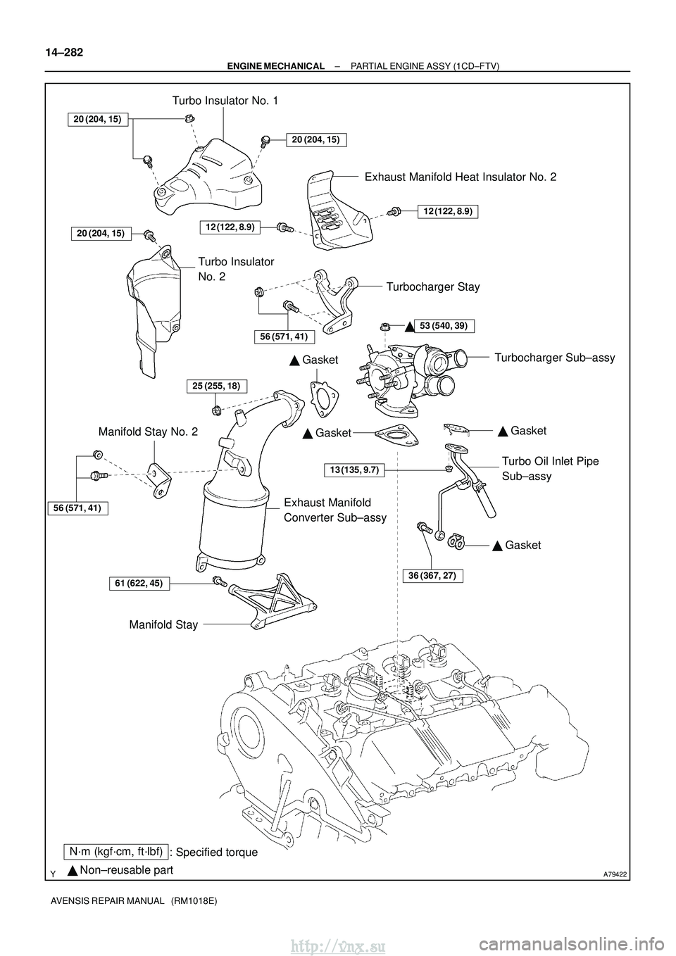
A79422
N´m (kgf´cm, ft´lbf): Specified torque
� Non±reusable part �
Gasket
� Gasket
�
Gasket
20 (204, 15)
20 (204, 15)
53 (540, 39)
13 (135, 9.7)
36 (367, 27)61 (622, 45)
56 (571, 41)
25 (255, 18)
Turbo Insulator No. 1
Exhaust Manifold Heat Insulator No. 2
Turbocharger Stay Turbocharger Sub±assy
Turbo Oil Inlet Pipe
Sub±assy
Manifold Stay
Manifold Stay No. 2
Exhaust Manifold
Converter Sub±assy
Turbo Insulator
No. 2
�
20 (204, 15)
12 (122, 8.9)
56 (571, 41)
�
Gasket
12 (122, 8.9)
14±282
±
ENGINE MECHANICAL PARTIAL ENGINE ASSY (1CD±FTV)
AVENSIS REPAIR MANUAL (RM1018E)
http://vnx.su
Page 661 of 2234

14±291
AVENSIS REPAIR MANUAL (RM1018E)
56.REMOVE IDLER PULLEY SUB±ASSY (See page 14±307)
57.REMOVE TIMING BELT NO.2 COVER (See page")
A15985
A78280
±
ENGINE MECHANICALPARTIAL ENGINE ASSY(1CD±FTV)
14±291
AVENSIS REPAIR MANUAL (RM1018E)
56.REMOVE IDLER PULLEY SUB±ASSY (See page 14±307)
57.REMOVE TIMING BELT NO.2 COVER (See page 14±307)
58.REMOVE TIMING BELT NO.1 COVER (See page 14±307)
59.REMOVE TIMING BELT GUIDE
60.REMOVE TRANSVERSE ENGINE ENGINE MOUNTING BRACKET (See page 14±307)
61.SET NO. 1 CYLINDER TO TDC/COMPRESSION (See page 14±307)
62.REMOVE TIMING BELT (See page 14±307)
HINT:
If re±use the timing belt, draw an arrow which indicates the engine rev\
olution direction on the belt and put
match marks on the pulleys and the belt before removing. This operation will \
be very helpful when re±instal-
ling the timing belt.
63.REMOVE GENERATOR ASSY
64.REMOVE GENERATOR BRACKET NO.1
(a)Remove the 2 bolts and the generator bracket.
65.REMOVE V±RIBBED BELT TENSIONER ASSY
66.REMOVE OIL FILTER BRACKET SUB±ASSY
(a)Remove the bolt and 2 nuts, and then remove the oil filter
bracket and the gasket.
67.REMOVE TURBO INSULATOR NO.2 (See page 13±11)
68.REMOVE TURBO INSULATOR NO.1 (See page 13±11)
69.REMOVE EXHAUST MANIFOLD HEAT INSULATOR NO.2 (See page 13±11)
70.REMOVE MANIFOLD STAY NO.2 (See page 13±11)
71.REMOVE MANIFOLD STAY (See page 13±11)
72.REMOVE EXHAUST MANIFOLD CONVERTER SUB±ASSY (See page 13±11)
73.REMOVE TURBOCHARGER STAY (See page 13±11)
74.DISCONNECT TURBO WATER HOSE NO.1 (See page 13±11)
75.DISCONNECT TURBO WATER HOSE NO.2 (See page 13±11)
76.SEPARATE TURBO OIL INLET PIPE SUB±ASSY (See page 13±11)
77.REMOVE TURBO OIL OUTLET PIPE NO.2 (See page 13±11)
78.REMOVE TURBOCHARGER SUB±ASSY (See page 13±11) 79. DISCONNECT WATER BY±PASS HOSE NO.3
http://vnx.su
Page 669 of 2234

14±299
AVENSIS REPAIR MANUAL (RM1018E)
132.INSTALL VACUUM PUMP ASSY
(a)Install 2 new O±rings t")
A79196
New O±Ring
New O±Ring
A79182
Collar
Groove
±
ENGINE MECHANICALPARTIAL ENGINE ASSY(1CD±FTV)
14±299
AVENSIS REPAIR MANUAL (RM1018E)
132.INSTALL VACUUM PUMP ASSY
(a)Install 2 new O±rings to the vacuum pump.
(b)Align the key of the vacuum pump with the keyway of the
exhaust camshaft, insert the vacuum pump into place.
Secure the pump with the 2 bolts.
Torque: 21 N �m (214 kgf�cm, 15 ft�lbf)
133.INSTALL EGR VALVE ASSY
(a)Install a new gasket and the EGR valve with the bolt and 2 nuts. Torque: 18 N �m (184 kgf�cm, 13 ft�lbf)
134.INSTALL INTAKE AIR CONNECTOR SUB±ASSY
(a)Install a new gasket and the intake air connector with diesel throttle b\
ody with the bolt and 2 nuts. Torque: 21 N �m (214 kgf�cm, 15 ft�lbf)
135.INSTALL WATER OUTLET SUB±ASSY
(a)Install a new gasket and the water outlet with the 2 bolts. Torque: 21 N �m (214 kgf�cm,15 ft�lbf)
136.INSTALL OIL COOLER ASSY (See page 17±32)
137.INSTALL EXHAUST MANIFOLD
(a)Install a new gasket, the exhaust manifold and the 8 col-lars with new 8 nuts.
Torque: 47 N �m (479 kgf�cm, 35 ft�lbf)
HINT:
When installing the collars, pay attention to the mounting
orientation. Ring groove of the collar should be outside. Refer
to the illustration on the left.
138.INSTALL EGR PIPE SUB±ASSY NO.1
(a)Install 2 new gaskets and the EGR pipe with the bolt and 4 new nuts. Torque:
37 N�m (375 kgf�cm,27 ft�lbf) for bolt
25 N�m (250 kgf�cm,18 ft�lbf) for nut
139.INSTALL TURBOCHARGER SUB±ASSY (See page 13±11)
140.INSTALL TURBO OIL INLET PIPE SUB±ASSY (See page 13±11)
141.INSTALL TURBOCHARGER STAY (See page 13±11)
142.INSTALL EXHAUST MANIFOLD CONVERTER SUB±ASSY (See page 13±11)
143.INSTALL MANIFOLD STAY NO.2 (See page 13±11)
144.INSTALL EXHAUST MANIFOLD HEAT INSULATOR NO.2 (See page 13±11)
145.INSTALL TURBO INSULATOR NO.1 (See page 13±11)
146.INSTALL TURBO INSULATOR NO.2 (See page 13±11)
http://vnx.su
Page 739 of 2234
(b)
(b)
(a)
A77857
A76194
Wooden
Block
Gasket
±
EXHAUST EXHAUST PIPE ASSY (1CD±FTV)
15±11
AVENSIS REPAIR MANUAL (RM1018E)
3. REMOVE EXHAUST PIPE ASSY FRONT
(a) Remove the 2 bolts and 2")
A78272
(a)(b)
(b)
(a)
A77857
A76194
Wooden
Block
Gasket
±
EXHAUST EXHAUST PIPE ASSY (1CD±FTV)
15±11
AVENSIS REPAIR MANUAL (RM1018E)
3. REMOVE EXHAUST PIPE ASSY FRONT
(a) Remove the 2 bolts and 2 compression springs.
(b) Disconnect the 2 exhaust pipe supports and remove the
exhaust pipe front.
(c) Remove the gasket from the manifold converter.
4. INSTALL EXHAUST PIPE ASSY FRONT
(a) Using vernier calipers, measure the free length of the compression spring.
Minimum Length: 41.5 mm (1.634 in.)
If the minimum length is less than minimum, replace the com-
pression spring.
(b) Using a plastic hammer and a wooden block, tap in a new gasket until its surface is flush with the exhaust manifold.
NOTICE:
�Tap in the gasket in the correct direction.
�Do not reuse the removed gasket.
�Be sure not to push in the gasket when installing the
exhaust pipe.
(c) Connect the 2 exhaust pipe supports and install the ex-
haust pipe front with the 2 compression springs and 2
bolts.
Torque: 43 N� m (440 kgf�cm, 32 ft�lbf)
http://vnx.su
Page 740 of 2234
A77857
A78440
New Gasket
15±12
±
EXHAUST EXHAUST PIPE ASSY (1CD±FTV)
AVENSIS REPAIR MANUAL (RM1018E)
5. INSTALL EXHAUST PIPE ASSY TAIL
(a) Using vernier calipers, measure the free length of the compression spring.
Minimum Length: 38.5 mm (1.515 in.)
If the minimum length is less than minimum, replace the com-
pression spring.
(b) Install a new gasket to the pipe front converter as shown in the illustration.
(c) Connect the 3 exhaust pipe supports and install the ex- haust pipe tail with the 2 compression springs and 2 bolts.
Torque: 43 N� m (440 kgf�cm, 32 ft�lbf)
6. CHECK FOR EXHAUST GAS LEAKS
7. INSTALL FLOOR PANEL BRACE FRONT Torque: 30 N �m (302 kgf� cm, 22 ft�lbf)
http://vnx.su

AVENSIS REPAIR MANUAL (RM1018E)
5. INSTALL EXHAUST PIPE ASSY TAIL
(a) Using vernier calipers, measure the free length of the c")