Page 1296 of 1574
9Q-2 ROOF
SUN ROOF
SCHEMATIC AND ROUTING DIAGRAMS
Page 1305 of 1574

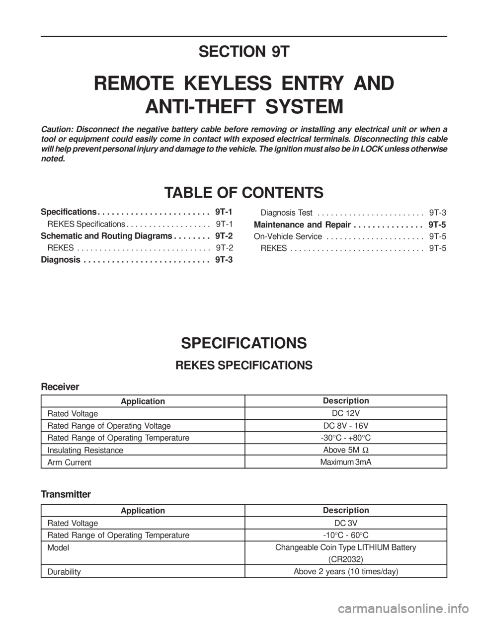
SECTION 9T
REMOTE KEYLESS ENTRY ANDANTI-THEFT SYSTEM
Caution: Disconnect the negative battery cable before removing or installing any electrical unit or when a tool or equipment could easily come in contact with exposed electrical terminals. Disconnecting this cablewill help prevent personal injury and damage to the vehicle. The ignition must also be in LOCK unless otherwisenoted.
TABLE OF CONTENTS
Specifications . . . . . . . . . . . . . . . . . . . . . . . . 9T-1
REKES Specifications . . . . . . . . . . . . . . . . . . . 9T-1
Schematic and Routing Diagrams . . . . . . . . 9T-2
REKES . . . . . . . . . . . . . . . . . . . . . . . . . . . . . . 9T-2
Diagnosis . . . . . . . . . . . . . . . . . . . . . . . . . . . 9T-3
SPECIFICATIONS
REKES SPECIFICATIONS Diagnosis Test . . . . . . . . . . . . . . . . . . . . . . . .
9T-3
Maintenance and Repair . . . . . . . . . . . . . . . 9T-5
On-Vehicle Service . . . . . . . . . . . . . . . . . . . . . . 9T-5
REKES . . . . . . . . . . . . . . . . . . . . . . . . . . . . . . 9T-5
Transmitter
Description DC 3V
-10 °C - 60 °C
Changeable Coin Type LITHIUM Battery (CR2032)
Above 2 years (10 times/day)
Application
Rated Voltage
Rated Range of Operating Temperature Model Durability
Description DC 12V
DC 8V - 16V
-30 °C - +80 °C
Above 5M �
Maximum 3mA
Application
Rated Voltage
Rated Range of Operating Voltage
Rated Range of Operating Temperature Insulating Resistance Arm Current
Receiver
Page 1307 of 1574
9U-2 CONTROL UNITS AND SYSTEM
STICS
SCHEMATIC AND ROUTING DIAGRAMS
Page 1320 of 1574
1A-8 MUSSO-SPORTS
SUPPLEMENT MAINTENANCE AND REPAIR
VACUUM PUMP AND VACUUM LINE This diagnosis procedure checks for vacuum leaks and actuator's operation while performing the actual control of EGR unit through vacuum lines in vacuum pump. The following special service tools should be used for this procedure.
001 589 73 21 00
Manual Vacuum Pump
Multi-Tester 201 589 13 21 00
Vacuum Tester
KAA5A2P0
KAA5A2R0 KAA5A2Q0
VACUUM LINE TEST Check the EGR system when the vehicle produces excessive exhaust gas. Check the vacuum lines for leaks and blocks. If there are not any faults, check the actuators controlled by EGR control unit. Install the tester in position according to the vacuum circuit diagram.
To prevent personal injury, beware of moving parts of engine.
Page 1340 of 1574
1A-28 MUSSO-SPORTS
SUPPLEMENT
30 BAT+
15 IGN 1
58 ILL
31 GND
2 3
107
B E
ClusterL
20 388
6 B4
B2 Multi-Function Switch
(Turn Signal Switch)
GY GY B1
RH
LH
5 9
ILL OFF ON
4
Hazard
Switch
G204 G301
G201
E
f10
10A
F2110A E
f9
60A
F7 15A
1 GW
YB BG RG
GW LY
GL YW
B
BB
B Blinker Unit Y
W
GR
GR
4
S202 E
f2 80A
2 4G
G W
G
G
1 2
G
G102 G204
3 1
G303
24
G101
G101 31
FRT LH
Turn Signal Lamp
(Head Lamp)
RR LH
Turn SignalLamp
(Tail Lamp) FRT RH
Turn Signal Lamp
(Head Lamp)
RR RH
Turn SignalLamp
(Tail Lamp)
"28"
Cluster
YYY
B
B
B "25"
Cluster
C905 2
C203
5
C904 2 C108
C206
C905 8
3 C904
3
C101
4
C1031
11C905
6
C101
17
Fender Fender
C904
7
ELECTRICAL WIRING DIAGRAM
1. TURN SIGNAL LAMP, HAZARD LAMP CIRCUIT
Page 1348 of 1574
1. HOW TO READ ELECTRICAL WIRING DIAGRAM ........................ 1-2
2. CIRCUIT IDENTIFICATION SYMBOL ............................................... 1-3
3. FUNCTION OF POWER SUPPLY LINE ............................................ 1-3
4. WIRING HARNESS COLOR IDENTIFICATION................................ 1-3
5. HOW TO CHECK TERMINAL NUMBER OF CONNECTOR .......... 1-3 CONTENTS
SECTION 1
HOW TO USE ELECTRICAL WIRING DIAGRAM
Page 1349 of 1574

1-2 HOW TO USE ELECTRICAL WIRING DIAGRAM
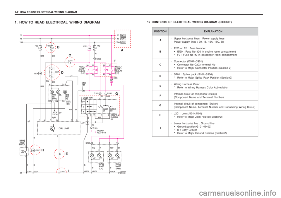
1. HOW TO READ ELECTRICAL WIRING DIAGRAM1) CONTENTS OF ELECTRICAL WIRING DIAGRAM (CIRCUIT)
POSITION EXPLANATION
- Upper horizontal lines : Power supply lines
- Power supply lines : 30, 15, 15A, 15C, 58
- Ef20 or F2 : Fuse Number
• Ef20 : Fuse No #20 in engine room compartment
F2 : Fuse No #2 in passenger room compartment
- Connector (C101~C901) Connector No C203 terminal No1
* Refer to Major Connector Position (Section 2)
- S201 : Splice pack (S101~S306) * Refer to Major Splice Pack Position (Section2)
- Wiring Harness Color * Refer to Wiring Harness Color Abbreviation
- Internal circuit of component (Relay) (Component Name and Terminal Number)
- Internal circuit of component (Switch) (Component Name, Terminal Number and Connecting Wiring Circuit)
- J201 : Joint(J101~J401) * Refer to Major Joint Position(Section2)
- Lower horizontal line : Ground line Ground position(G101~G402)
B : Body Ground
* Refer to Major Ground Position (Section2)
A
B C D E
F
G
H
I
A
B
C
D F
G
E I
H
Page 1350 of 1574

HOW TO USE ELECTRICAL WIRING DIAGRAM 1-3
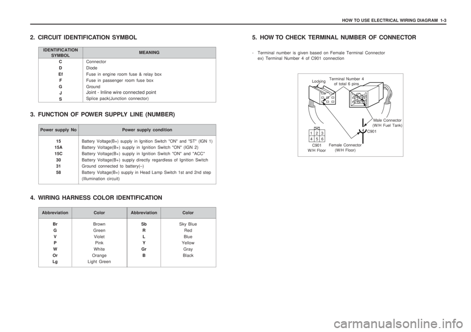
Connector DiodeFuse in engine room fuse & relay box Fuse in passenger room fuse box Ground Joint - Inline wire connected point Splice pack(Junction connector)
C D
Ef F
G J
S
2. CIRCUIT IDENTIFICATION SYMBOL
3. FUNCTION OF POWER SUPPLY LINE (NUMBER)
IDENTIFICATION SYMBOL MEANING
Power supply No Power supply condition
Battery Voltage(B+) supply in Ignition Switch "ON" and "ST" (IGN 1)
Battery Voltage(B+) supply in Ignition Switch "ON" (IGN 2) Battery Voltage(B+) supply in Ignition Switch "ON" and "ACC"Battery Voltage(B+) supply directly regardless of Ignition Switch Ground connected to battery(
–)
Battery Voltage(B+) supply in Head Lamp Switch 1st and 2nd step
(Illumination circuit)
15
15A 15C
30 31 58
Abbreviation Color
BrownGreen Violet Pink
White
Orange
Light Green
Br
GV P
W
Or
LgAbbreviation Color
Sky BlueRed
Blue
Yellow
Gray
Black
Sb
RL Y
Gr B
4. WIRING HARNESS COLOR IDENTIFICATION 5. HOW TO CHECK
TERMINAL NUMBER OF CONNECTOR
- Terminal number is given based on Female Terminal Connector ex) Terminal Number 4 of C901 connection
Locking Terminal Number 4
of total 6 pins
Male Connector
(W/H Fuel Tank)
4 C901
Female Connector (W/H Floor)
C901
W/H Floor 13
2
46 5