2003 SSANGYONG MUSSO adding oil
[x] Cancel search: adding oilPage 889 of 1574

5A-30 AUTOMATIC TRANSMISSION
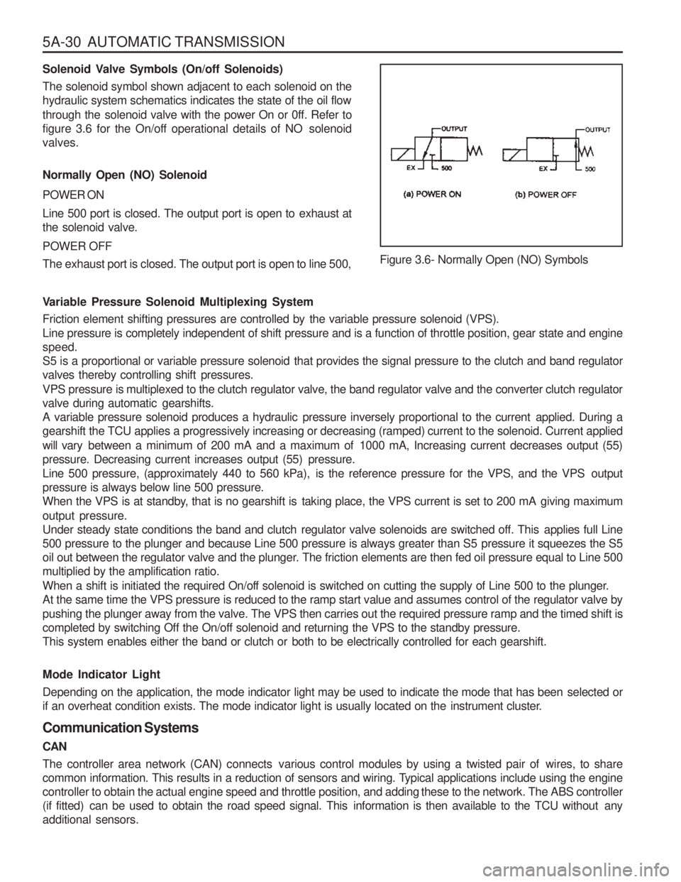
Solenoid Valve Symbols (On/off Solenoids)
The solenoid symbol shown adjacent to each solenoid on the
hydraulic system schematics indicates the state of the oil flow
through the solenoid valve with the power On or 0ff. Refer to
figure 3.6 for the On/off operational details of NO solenoidvalves. Normally Open (NO) Solenoid POWER ON
Line 500 port is closed. The output port is open to exhaust at the solenoid valve. POWER OFF
The exhaust port is closed. The output port is open to line 500,Figure 3.6- Normally Open (NO) Symbols
Variable Pressure Solenoid Multiplexing System
Friction element shifting pressures are controlled by the variable pressure solenoid (VPS).
Line pressure is completely independent of shift pressure and is a function of throttle position, gear state and enginespeed.
S5 is a proportional or variable pressure solenoid that provides the signal pressure to the clutch and band regulator
valves thereby controlling shift pressures.
VPS pressure is multiplexed to the clutch regulator valve, the band regulator valve and the converter clutch regulator
valve during automatic gearshifts.
A variable pressure solenoid produces a hydraulic pressure inversely proportional to the current applied. During a
gearshift the TCU applies a progressively increasing or decreasing (ramped) current to the solenoid. Current applied will vary between a minimum of 200 mA and a maximum of 1000 mA, Increasing current decreases output (55)
pressure. Decreasing current increases output (55) pressure.
Line 500 pressure, (approximately 440 to 560 kPa), is the reference pressure for the VPS, and the VPS outputpressure is always below line 500 pressure.
When the VPS is at standby, that is no gearshift is taking place, the VPS current is set to 200 mA giving maximum output pressure.
Under steady state conditions the band and clutch regulator valve solenoids are switched off. This applies full Line
500 pressure to the plunger and because Line 500 pressure is always greater than S5 pressure it squeezes the S5
oil out between the regulator valve and the plunger. The friction elements are then fed oil pressure equal to Line 500multiplied by the amplification ratio.
When a shift is initiated the required On/off solenoid is switched on cutting the supply of Line 500 to the plunger.
At the same time the VPS pressure is reduced to the ramp start value and assumes control of the regulator valve by
pushing the plunger away from the valve. The VPS then carries out the required pressure ramp and the timed shift is
completed by switching Off the On/off solenoid and returning the VPS to the standby pressure.
This system enables either the band or clutch or both to be electrically controlled for each gearshift. Mode Indicator Light
Depending on the application, the mode indicator light may be used to indicate the mode that has been selected or
if an overheat condition exists. The mode indicator light is usually located on the instrument cluster. Communication Systems CAN
The controller area network (CAN) connects various control modules by using a twisted pair of wires, to share
common information. This results in a reduction of sensors and wiring. Typical applications include using the engine
controller to obtain the actual engine speed and throttle position, and adding these to the network. The ABS controller
(if fitted) can be used to obtain the road speed signal. This information is then available to the TCU without anyadditional sensors.
Page 938 of 1574

AUTOMATIC TRANSMISSION 5A-79
ADJUSTMENTS
HYDRAULIC SYSTEM
The procedures detailed below should be followed in the event that the self test procedure detailed in section 6, or a
defect symptom, indicates that there is a fault in the hydraulic system.
When making adjustments to the transmission, select the appropriate procedures from the following preliminary checks. � Conduct a transmission fluid test procedure, refer to section 7.2.
� Check the manual linkage adjustment (refer to the vehicle workshop manual).
� Check engine idle speed (refer to Section 7.3).
� Conduct a stall test (it is outside the scope of this publication to detail this procedure)
� conduct a road test (it is outside the scope of this publication to detail this procedure).
TRANSMISSION FLUID TEST PROCEDURE
Checking Transmission Fluid Level
This procedure is to be used when checking a concern with the fluid level in a vehicle. A low fluid level will result in
gearshift loss or delay if driven when the vehicle is cold.
The vehicle is first checked for transmission diagnostic messages (refer to section 6). If the vehicle has a speedo fault
it is possible for the oil level to be low.
The vehicle is to be test driven to determine if there is an abnormal delay when selecting drive or reverse, or loss of
drive. One symptom of low oil level is a momentary loss of drive when driving the vehicle around a comer. Also when
the transmission fluid level is low, a loss of drive may occur when the transmission oil temperature is low.
If there is no loss of drive when the vehicle is driven warm and a speedo fault is registered, then fluid should be addedto the transmission.
Checking, Adding Fluid and Filling
When adding or changing transmission oil use only Castrol TQ 95 automatic transmission fluid (A TF) or other approved
fluids. The use of incorrect oil will cause the performance and durability of the transmission to be severely degraded. Do not underfill the transmission. Incorrect tilling may cause damage to the transmission. The fluid level setting
procedure is detailed below. Notice
When a transmission is at operating temperature hot transmission fluid may come out of the case if the fill plug is
removed. 9 the transmission is at operating temperature allow two hours for cooling prior to removing the plug.
1. If the vehicle is at operating temperature allow the vehicle to cool down for two, but no greater than four hours before adding transmission fluid (this will allow the transmission to be within the correct temperaturerange).
While hot the ATF level is higher and removing the plug may result in oil being expelled from the filler hole. This
will result in the level being low.
2. The transmission selector is to be in Park. Switch the engine off.
3. Raise the vehicle on a hoist (or leave over a service pit).
4. Clean all dirt from around the service fill plug prior to removing the plug. Remove the oil service fill plug. Clean the fill plug and check that there is no damage to the ‘O’ ring.
Install the filler pump into the filler hole.
5. Lower the vehicle with the filler pump still connected and partially fill the transmission.
Start the vehicle in Park with the Parking brake and foot brake applied with the engine idling, cycle the transmission
gear selector through all positions, adding ATF until gear application is felt.
Page 939 of 1574

5A-80 AUTOMATIC TRANSMISSION6. Switch off the engine and raise the vehicle on the hoist, if applicable, ensuring that the vehicle is level.
7. Three minutes after the engine has stopped, but no longer than one hour, remove the filler pump, The correct level is reached when ATF is aligned with the bottom of the filler hole. If the correct level is not reached, then add
a small quantity of ATF to the correct level.
8. Replace the transmission filler plug and clean all remnants of ATF on the transmission and vehicle.
9. Tighten the transmission filler plug to specification.
Checking, Adding Fluid and Filling - Drained or Dry Transmission
To set the correct fluid level proceed as follows. 1. Set the transmission selector to Park and switch the engine off.
2. Raise the vehicle on a hoist (or leave over a service pit).
3. Clean all dirt from around the service fill plug prior to removing the plug, Remove the oil service fill plug. Clean the fill plug and check that there is no damage to the ‘O’ ring. Install the filler pump into the filler hole.
4. Lower the vehicle with the filler pump still connected and partially fill the transmission. This typically requires approximately :
a. If the transmission torque converter is empty:
9.0 litres - 4WD9.0 litres - RWD
b. If the transmission torque converter is full: 4.5 litres - 4WD4.5 litres - RWD
5. Start the vehicle in Park with the Parking brake and foot brake applied with the engine idling, cycle the transmission gear selector through all positions, adding ATF until gear application is felt.
6. Then add an additional 0.5 litres of ATF.
7. Switch off the engine and raise the vehicle on the hoist. Remove the filler pump and replace the filler plug. The plug shall be tightened to specification.
8. The vehicle is then to be driven between 3.5 and 4.5 kilometers at light throttle so that the engine does not exceed 2500 rpm. This should result in the transmission temperature being in the range 50 to 60 °C.
9. With the engine idling, cycle the transmission selector through all gear positions with the brake applied.
10. Stop the engine. Raise the vehicle on the hoist, if applicable ensuring the vehicle is level.
11. Three minutes after the engine has stopped, but no longer than one hour, remove the filler plug. The correct level is reached when ATF is aligned with the bottom of the filler hole. If the correct level is not reached, then add
a small quantity of ATP to the correct level.
12. Replace the transmission filler plug and clean all remnants of ATF on the transmission and vehicle. Tighten the transmission Filler plug to specification.
ELECTRONIC ADJUSTMENTS Idle Speed Adjustment
Carry out the adjustments to the idle speed as detailed in the workshop manual.
Throttle Position Calibration
Should the throttle position data stored in the TCU be lost or be out of specification, as indicated by a diagnostic
trouble message, it may be re-established by the following procedure. � Check that the hot engine idle speed is within specification.
� Allow the engine to idle in ‘Drive ’ for 60 seconds with the air conditioner (if fitted) turned off. The closed throttle
reference point in the TCU has now been set.
Switch the engine off but leave the ignition on. Hold the accelerator pedal on the floor for 60 seconds. The wide open
throttle reference point in the TCU has now been set.