Page 540 of 1574

1F1-8 M162 ENGINE CONTROLSCruise control acceleration failure Cruise control deceleration failureECU failure(RAM)ECU failure(EPROM) Servo motor control output inter-ruption memory failureServo motor open/shortUnprogramed ECU with Immobilizer Uncoded ECU ECU failure(NVRAM checksum failure) ECU failure(coding ID checksum failure)ECU failure(coding checksum failure)ECU failure(programing checkusm failure)ABD input signal short(power) ABD input signal short(GND) Low pedal valve sensor SP1 voltageHigh pedal valve sensor SP1 voltageLow pedal valve sensor SP2 voltageHigh pedal valve sensor SP2 voltageDifferent pedal valve sensor signal(1,2) Pedal valve sensor 1,2 failure
HFM sensor, and throttle position sensorfailureECU failure(incompatible CPU)ECU failure(CPUs communication failure) ECU failure(CPU(2) configuration failure) ECU failure(CPU(2) fault)ECU failure(CPU run time failure betweenCPUs)No.5 injector short(PWR)
93969798 99
100 101 102 103 104 105108 109 11 0
11 6
11 7
11 9
120 121 122123125126 127 129130131132 Short learning control failureLambda control failure (rich stop)Lambda control failure (lean stop) Lambda idle adaptation failure(above rich threshold) Lambda idle adaptation failure(below lean threshold)learning control failure(rich, low load)learning control failure(lean, low load) learning control failure(rich, high load) learning control failure(lean, high load)Low throttle position sensor(IP1) voltageHigh throttle position sensor(IP1) voltageLow throttle position sensor(IP2) voltage High throttle position sensor(IP2) voltage Throttle actuator learning data faultThrottle actuator learning control failureExceed fuel-cut safety timeThrottle valve return spring failureCruise control interruption memory failure Throttle actuator failure Pedal module position sensor signal failureDifferent HFM signal with throttle potentiometerBoth throttle potentiometer(IP1&IP2) failureIPS1 with IPS2 High permanent throttle signal Message counter failure
� cruise control ’OFF ’
Vehicle speed signal failure
Vehicle speed signal failureCruise control lever failure 133134 136 137 139 140 141142 143 144145146150 151 160161162163164 167 185 186 187 188 189190 192
Failure
code DescriptionFailure
code Description
Page 594 of 1574

1F1-62 M162 ENGINE CONTROLS
PURGE SWITCHOVER VALVE
1 Purge Switchover Valve
2 Line to Engine
3 Line to Canister
4 Canister
Functions The fuel vaporization control system is installed to inhibit the fuel vaporized gas from discharging into the atmosphere. Thefuel vaporized gas that is accumulated in the canister abstractsthrough the purge switchover valve purification during the engine combustion (except the decreasing mode) and coolant temperature of over 80 °C. For this reason, the ECU transacts
the engine speed, air inflow quantity, coolant temperature, andintake temperature. The purge switchover valve is activated by the ECU frequency according with the engine rotating speed to adjust the purification rate. The purification rate is determined by the continuous valve opening interval. The purge switchover valve is activated by the ECU for the following conditions :
� Coolant temperature of over 80 °C
� Engine speed of over 1000rpm
� 2 Minutes after starting
� When the fuel cut-off mode is not activated
Page 616 of 1574
OM600 ENGINE CONTROLS 1F3-5
VACUUM CONTROL SYSTEM TEST
2 Engine Cut-Off Valve (Ignition Key Switch)
3 Auto-locking Hub Solenoid Valve
4 Engine Stop Valve Unit
5 PLA Vacuum Unit (Idle Speed Adjustment)
6 Engine
7 Vacuum Pump830
° Thermovalve
9 Fuel Injection Pump
10 Filter with Restriction
11 Check V alve
12 Modulating Pressure Line (Automatic T/M)
Test Data
Idle Speed Increase Permissible Pressure Drop of System At least 100 rpm at approx. 500mbr
400 - 500mbar approx. 1 min.
Page 1315 of 1574

MUSSO-SPORTS 1A-3
SUPPLEMENT
HUBER EGR
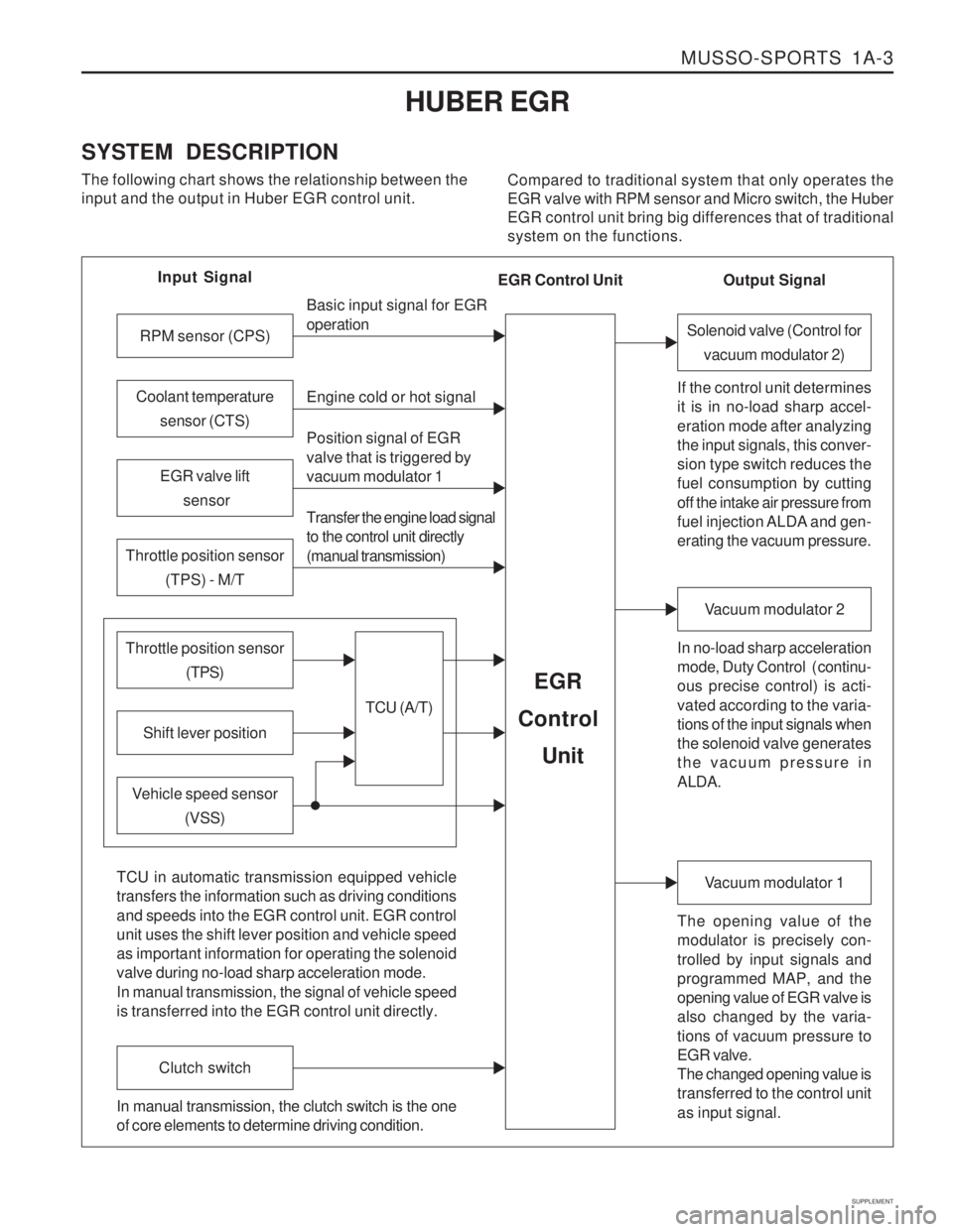
SYSTEM DESCRIPTION The following chart shows the relationship between the input and the output in Huber EGR control unit. Compared to traditional system that only operates theEGR valve with RPM sensor and Micro switch, the HuberEGR control unit bring big differences that of traditionalsystem on the functions.
Input Signal
RPM sensor (CPS)
EGR valve lift sensor
Throttle position sensor (TPS) - M/T
Shift lever position
Throttle position sensor (TPS)
Vehicle speed sensor(VSS) Basic input signal for EGR operation Engine cold or hot signal
Position signal of EGR valve that is triggered by vacuum modulator 1 Transfer the engine load signal to the control unit directly (manual transmission)
TCU (A/T)
EGR
Control
Unit
Coolant temperature sensor (CTS)
Solenoid valve (Control forvacuum modulator 2)
If the control unit determines it is in no-load sharp accel- eration mode after analyzing the input signals, this conver- sion type switch reduces the fuel consumption by cutting off the intake air pressure from
fuel injection ALDA and gen- erating the vacuum pressure. In no-load sharp acceleration
mode, Duty Control ( continu- ous precise control) is acti- vated according to the varia- tions of the input signals when the solenoid valve generates the vacuum pressure in ALDA.
Vacuum modulator 2
The opening value of the modulator is precisely con- trolled by input signals and programmed MAP, and the opening value of EGR valve is also changed by the varia- tions of vacuum pressure to EGR valve. The changed opening value is transferred to the control unit as input signal.
Vacuum modulator 1
TCU in automatic transmission equipped vehicle transfers the information such as driving conditions and speeds into the EGR control unit. EGR control unit uses the shift lever position and vehicle speed as important information for operating the solenoid valve during no-load sharp acceleration mode. In manual transmission, the signal of vehicle speed is transferred into the EGR control unit directly.
Clutch switch
In manual transmission, the clutch switch is the one of core elements to determine driving condition. Output Signal
EGR Control Unit