Page 1169 of 1574
FATC-HAVC 7D-13
Removal & Installation Procedure
1. Turn the ignition switch to OFF position.
2. Remove the digital clock.
3. Unscrew the screw from the center panel, pull out eachswitches and remove the center panel.
4. Unscrew the 6 screws and remove the audio control panel assembly.
5. Unscrew the 4 screws and remove the airconditioner control panel assembly.
6. Installation should follow the removal procedure in the reverse order.
Page 1201 of 1574

SUPPLEMENTAL RESTRAINT SYSTEM(SRS) 8B-21
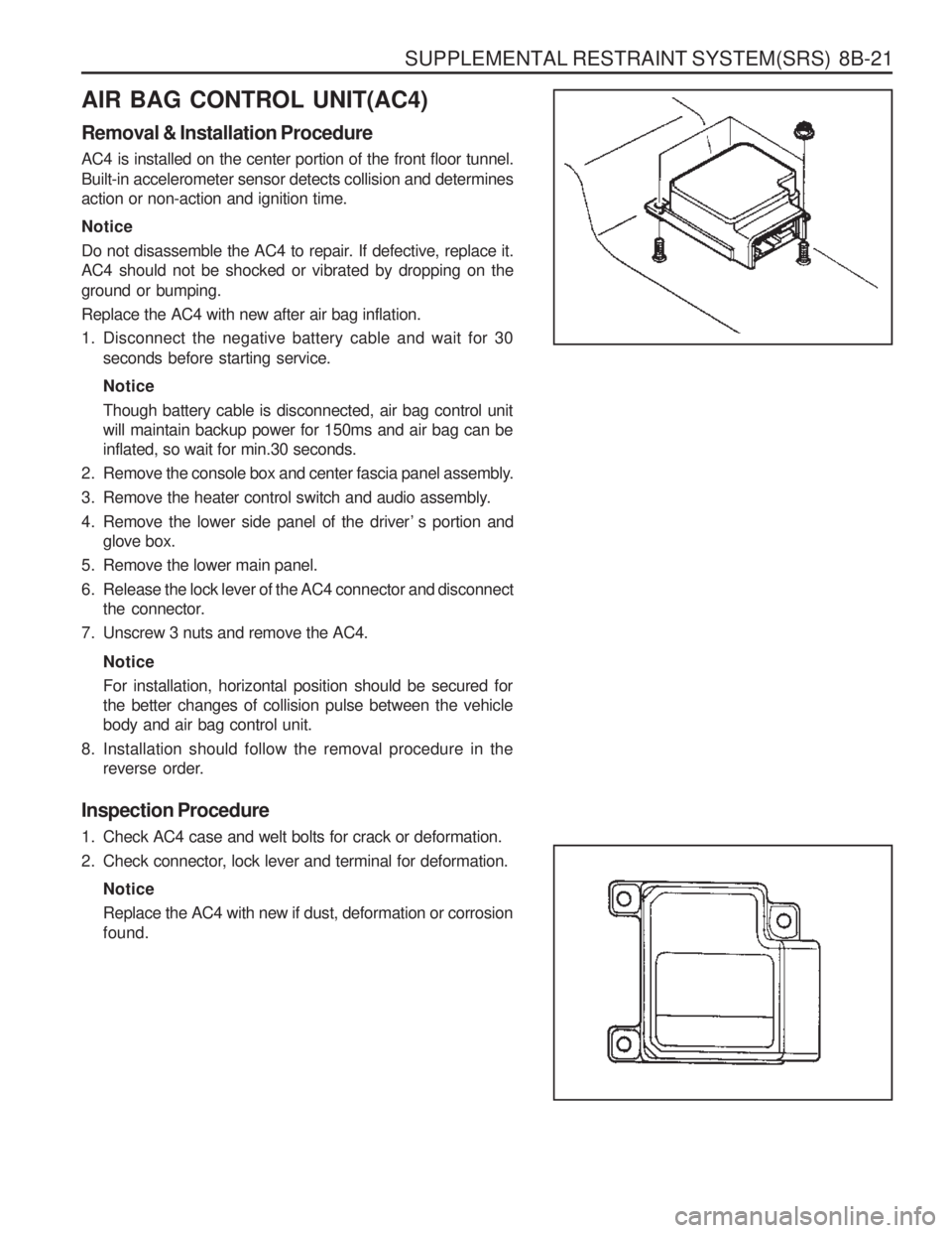
AIR BAG CONTROL UNIT(AC4) Removal & Installation Procedure AC4 is installed on the center portion of the front floor tunnel.
Built-in accelerometer sensor detects collision and determines action or non-action and ignition time. Notice
Do not disassemble the AC4 to repair. If defective, replace it. AC4 should not be shocked or vibrated by dropping on the ground or bumping. Replace the AC4 with new after air bag inflation.
1. Disconnect the negative battery cable and wait for 30seconds before starting service. Notice Though battery cable is disconnected, air bag control unit will maintain backup power for 150ms and air bag can beinflated, so wait for min.30 seconds.
2. Remove the console box and center fascia panel assembly.
3. Remove the heater control switch and audio assembly.
4. Remove the lower side panel of the driver ’ s portion and glove box.
5. Remove the lower main panel.
6. Release the lock lever of the AC4 connector and disconnect the connector.
7. Unscrew 3 nuts and remove the AC4.
NoticeFor installation, horizontal position should be secured for the better changes of collision pulse between the vehiclebody and air bag control unit.
8. Installation should follow the removal procedure in the reverse order.
Inspection Procedure
1. Check AC4 case and welt bolts for crack or deformation.
2. Check connector, lock lever and terminal for deformation. NoticeReplace the AC4 with new if dust, deformation or corrosion found.
Page 1208 of 1574

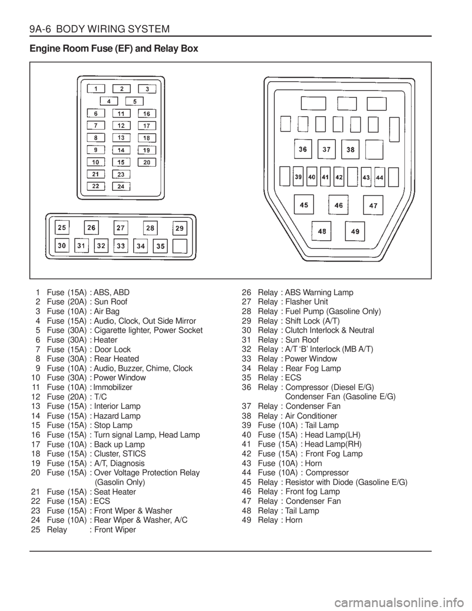
9A-6 BODY WIRING SYSTEM Engine Room Fuse (EF) and Relay Box1 Fuse (15A) : ABS, ABD
2 Fuse (20A) : Sun Roof
3 Fuse (10A) : Air Bag
4 Fuse (15A) : Audio, Clock, Out Side Mirror
5 Fuse (30A) : Cigarette lighter, Power Socket
6 Fuse (30A) : Heater
7 Fuse (15A) : Door Lock
8 Fuse (30A) : Rear Heated
9 Fuse (10A) : Audio, Buzzer, Chime, Clock
10 Fuse (30A) : Power Window
11 Fuse (10A) : Immobilizer
12 Fuse (20A) : T/C
13 Fuse (15A) : Interior Lamp
14 Fuse (15A) : Hazard Lamp
15 Fuse (15A) : Stop Lamp
16 Fuse (15A) : Turn signal Lamp, Head Lamp
17 Fuse (10A) : Back up Lamp
18 Fuse (15A) : Cluster, STICS
19 Fuse (15A) : A/T, Diagnosis
20 Fuse (15A) : Over Voltage Protection Relay (Gasolin Only)
21 Fuse (15A) : Seat Heater
22 Fuse (15A) : ECS
23 Fuse (15A) : Front Wiper & Washer
24 Fuse (10A) : Rear Wiper & Washer, A/C
25 Relay : Front Wiper 26 Relay : ABS Warning Lamp
27 Relay : Flasher Unit
28 Relay : Fuel Pump (Gasoline Only)
29 Relay : Shift Lock (A/T)
30 Relay : Clutch Interlock & Neutral
31 Relay : Sun Roof
32 Relay : A/T ‘B’ Interlock (MB A/T)
33 Relay : Power Window
34 Relay : Rear Fog Lamp
35 Relay : ECS
36 Relay : Compressor (Diesel E/G)
Condenser Fan (Gasoline E/G)
37 Relay : Condenser Fan
38 Relay : Air Conditioner
39 Fuse (10A) : Tail Lamp
40 Fuse (15A) : Head Lamp(LH)
41 Fuse (15A) : Head Lamp(RH)
42 Fuse (15A) : Front Fog Lamp
43 Fuse (10A) : Horn
44 Fuse (10A) : Compressor
45 Relay : Resistor with Diode (Gasoline E/G)
46 Relay : Front fog Lamp
47 Relay : Condenser Fan
48 Relay : Tail Lamp
49 Relay : Horn
Page 1210 of 1574

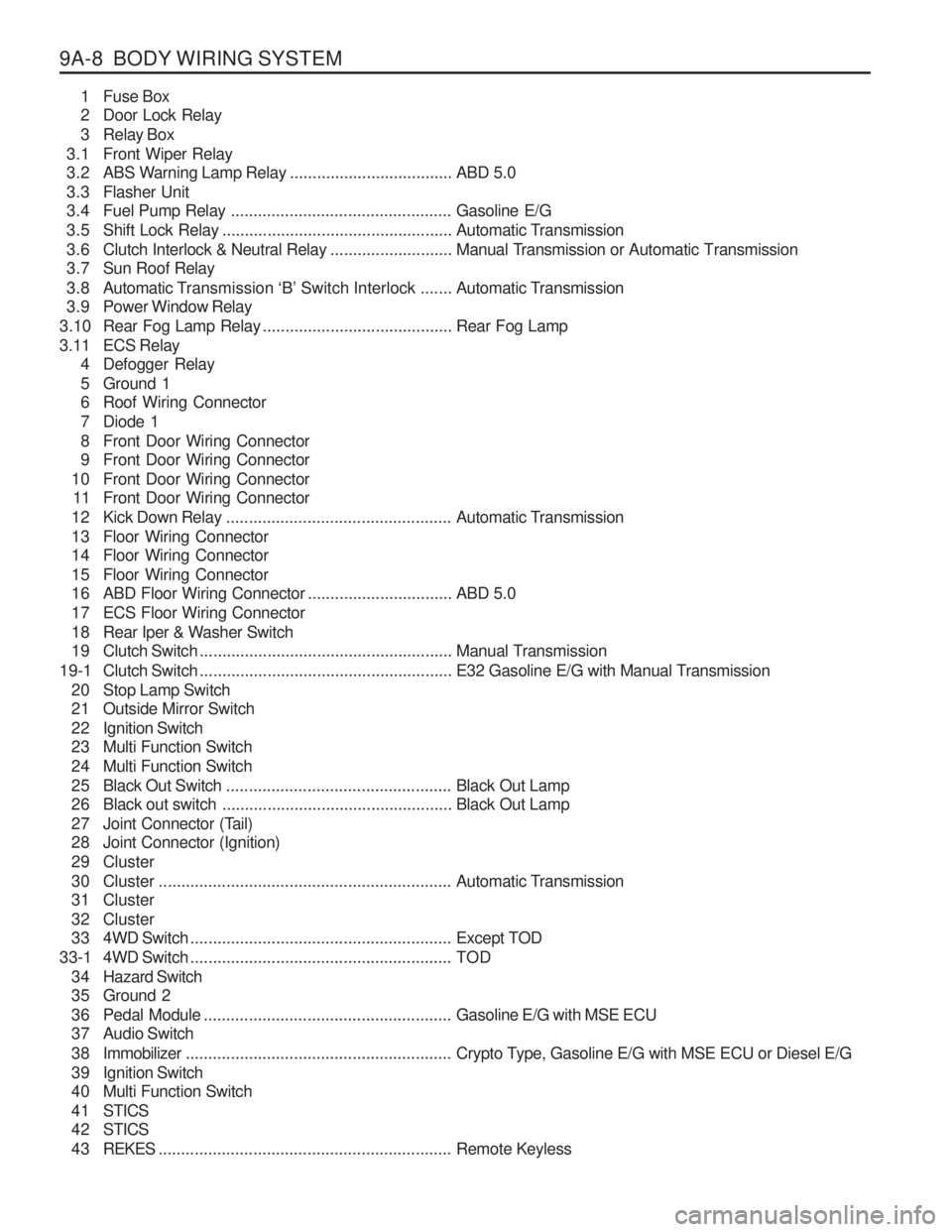
9A-8 BODY WIRING SYSTEM1 Fuse Box
2 Door Lock Relay
3 Relay Box
3.1 Front Wiper Relay
3.2 ABS Warning Lamp Relay ....................................ABD 5.0
3.3 Flasher Unit
3.4 Fuel Pump Relay ................................................. Gasoline E/G
3.5 Shift Lock Relay ................................................... Automatic Transmission
3.6 Clutch Interlock & Neutral Relay ...........................Manual Transmission or Automatic Transmission
3.7 Sun Roof Relay
3.8 Automatic T ransmission ‘B’ Switch Interlock ....... Automatic Transmission
3.9 Power Window Relay
3.10 Rear Fog Lamp Relay .......................................... Rear Fog Lamp
3.11 ECS Relay 4 Defogger Relay
5 Ground 1
6 Roof Wiring Connector
7 Diode 1
8 Front Door Wiring Connector
9 Front Door Wiring Connector
10 Front Door Wiring Connector 11 Front Door Wiring Connector
12 Kick Down Relay .................................................. Automatic Transmission
13 Floor Wiring Connector
14 Floor Wiring Connector
15 Floor Wiring Connector
16 ABD Floor Wiring Connector ................................ABD 5.0
17 ECS Floor Wiring Connector
18 Rear Iper & Washer Switch
19 Clutch Switch ........................................................ Manual Transmission
19-1 Clutch Switch ........................................................ E32 Gasoline E/G with Manual Transmission
20 Stop Lamp Switch
21 Outside Mirror Switch
22 Ignition Switch
23 Multi Function Switch
24 Multi Function Switch
25 Black Out Switch .................................................. Black Out Lamp
26 Black out switch ................................................... Black Out Lamp
27 Joint Connector (Tail)
28 Joint Connector (Ignition)
29 Cluster
30 Cluster ................................................................. Automatic Transmission
31 Cluster
32 Cluster
33 4WD Switch .......................................................... Except TOD
33-1 4WD Switch .......................................................... TOD
3 4 Hazard Switch
35 Ground 2
36 Pedal Module ....................................................... Gasoline E/G with MSE ECU
37 Audio Switch
3 8 Immobilizer ........................................................... Crypto Type, Gasoline E/G with MSE ECU or Diesel E/G
39 Ignition Switch
40 Multi Function Switch
4 1 STICS
4 2 STICS
4 3 REKES ................................................................. Remote Keyless
Page 1211 of 1574

BODY WIRING SYSTEM 9A-9
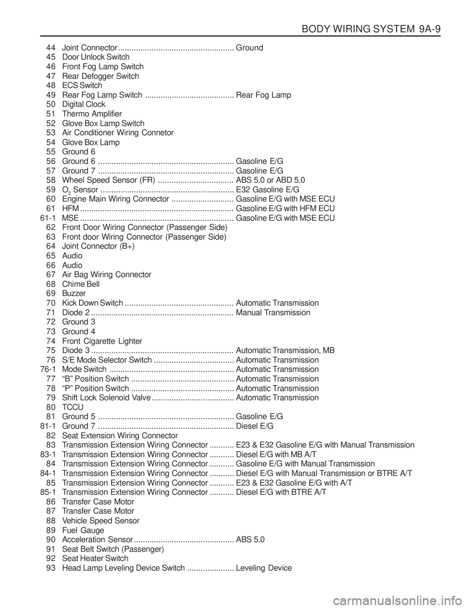
44 Joint Connector.................................................... Ground
45 Door Unlock Switch
46 Front Fog Lamp Switch
47 Rear Defogger Switch
4 8 ECS Switch
49 Rear Fog Lamp Switch ........................................Rear Fog Lamp
50 Digital Clock
51 Thermo Amplifier
52 Glove Box Lamp Switch
53 Air Conditioner Wiring Connetor
54 Glove Box Lamp
55 Ground 6
56 Ground 6 ............................................................. Gasoline E/G
57 Ground 7 ............................................................. Gasoline E/G
58 Wheel Speed Sensor (FR) ..................................ABS 5.0 or ABD 5.0
59 O 2 Sensor
............................................................ E32 Gasoline E/G
60 Engine Main Wiring Connector ............................Gasoline E/G with MSE ECU
61 HFM ..................................................................... Gasoline E/G with HFM ECU
61-1 MSE ..................................................................... Gasoline E/G with MSE ECU
62 Front Door Wiring Connector (Passenger Side)
63 Front door Wiring Connector (Passenger Side)
64 Joint Connector (B+)
65 Audio
66 Audio
67 Air Bag Wiring Connector
68 Chime Bell
6 9 Buzzer
70 Kick Down Switch ................................................. Automatic Transmission
71 Diode 2 ................................................................ Manual Transmission
72 Ground 3
73 Ground 4
74 Front Cigarette Lighter
75 Diode 3 ................................................................ Automatic Transmission, MB
76 S/E Mode Selector Switch ....................................Automatic Transmission
76-1 Mode Switch ........................................................ Automatic Transmission
77 “B” Position Switch .............................................. Automatic Transmission
78 “P” Position Switch .............................................. Automatic Transmission
79 Shift Lock Solenoid Valve .....................................Automatic Transmission
8 0 TCCU
81 Ground 5 ............................................................. Gasoline E/G
81-1 Ground 7 ............................................................. Diesel E/G
82 Seat Extension Wiring Connector
83 Transmission Extension Wiring Connector ...........E23 & E32 Gasoline E/G with Manual Transmission
83-1 T ransmission Extension Wiring Connector ...........Diesel E/G with MB A/T
84 Transmission Extension Wiring Connector ...........Gasoline E/G with Manual Transmission
84-1 T ransmission Extension Wiring Connector ...........Diesel E/G with Manual Transmission or BTRE A/T
85 Transmission Extension Wiring Connector ...........E23 & E32 Gasoline E/G with A/T
85-1 T ransmission Extension Wiring Connector ...........Diesel E/G with BTRE A/T
86 Transfer Case Motor
87 Transfer Case Motor
88 Vehicle Speed Sensor
89 Fuel Gauge
90 Acceleration Sensor ............................................. ABS 5.0
91 Seat Belt Switch (Passenger)
92 Seat Heater Switch
93 Head Lamp Leveling Device Switch .....................Leveling Device
Page 1255 of 1574
SECTION 9F
AUDIO SYSTEM
Caution: Disconnect the negative battery cable before removing or installing any electrical unit or when a tool or equipment could easily come in contact with exposed electrical terminals. Disconnecting this cable will help prevent personal injury and damage to the vehicle. The ignition must also be in LOCK unless otherwisenoted.TABLE OF CONTENTS
Schematic and Routing Diagrams . . . . . . . . 9F-2 Audio . . . . . . . . . . . . . . . . . . . . . . . . . . . . . . . 9F-2Diagnosis . . . . . . . . . . . . . . . . . . . . . . . . . . . 9F-3
General Diagnosis . . . . . . . . . . . . . . . . . . . . . 9F-3
Page 1256 of 1574
9F-2 AUDIO SYSTEM
AUDIO
SCHEMATIC AND ROUTING DIAGRAMS
0.3 GBRHEO(EXP)
LY
NO.13
Page 1257 of 1574
AUDIO SYSTEM 9F-3
DIAGNOSIS
GENERAL DIAGNOSIS
No sounds