Page 1061 of 1574
TRANSFER CASE (PART TIME 4408) 5D1-9
DIAGNOSTIC DIAGRAM
Page 1090 of 1574

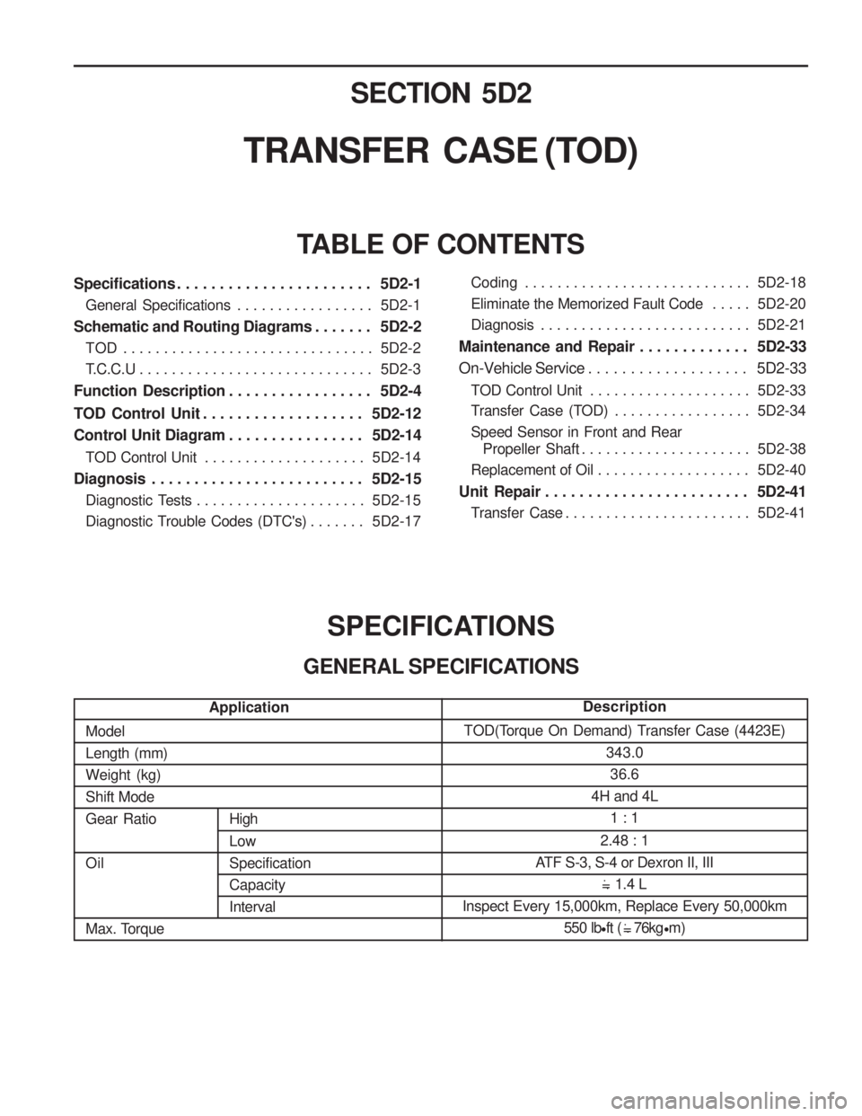
SECTION 5D2
TRANSFER CASE (TOD)
Specifications . . . . . . . . . . . . . . . . . . . . . . . 5D2-1General Specifications . . . . . . . . . . . . . . . . . 5D2-1
Schematic and Routing Diagrams . . . . . . . 5D2-2 TOD . . . . . . . . . . . . . . . . . . . . . . . . . . . . . . . 5D2-2
T.C.C.U . . . . . . . . . . . . . . . . . . . . . . . . . . . . . 5D2-3
Function Description . . . . . . . . . . . . . . . . . 5D2-4
TOD Control Unit . . . . . . . . . . . . . . . . . . . 5D2-12
Control Unit Diagram . . . . . . . . . . . . . . . . 5D2-14
TOD Control Unit . . . . . . . . . . . . . . . . . . . . 5D2-14
Diagnosis . . . . . . . . . . . . . . . . . . . . . . . . . 5D2-15 Diagnostic Tests . . . . . . . . . . . . . . . . . . . . . 5D2-15
Diagnostic Trouble Codes (DTC's) . . . . . . . 5D2-17
TABLE OF CONTENTS
SPECIFICATIONS
GENERAL SPECIFICATIONS
ModelLength (mm)Weight (kg)Shift ModeGear Ratio Oil
Max. Torque
High Low SpecificationCapacityInterval TOD(Torque On Demand) Transfer Case (4423E)
343.036.6
4H and 4L
1 : 1
2.48 : 1
ATF S-3, S-4 or Dexron II, III 1.4 L
Inspect Every 15,000km, Replace Every 50,000km 550 lbft ( 76kg m)
.
= .
.
= .
Application Description
Coding . . . . . . . . . . . . . . . . . . . . . . . . . . . . 5D2-18
Eliminate the Memorized Fault Code . . . . .
5D2-20
Diagnosis . . . . . . . . . . . . . . . . . . . . . . . . . . 5D2-21
Maintenance and Repair . . . . . . . . . . . . . 5D2-33
On-Vehicle Service . . . . . . . . . . . . . . . . . . . 5D2-33
TOD Control Unit . . . . . . . . . . . . . . . . . . . . 5D2-33
Transfer Case (TOD) . . . . . . . . . . . . . . . . . 5D2-34
Speed Sensor in Front and Rear Propeller Shaft . . . . . . . . . . . . . . . . . . . . . 5D2-38
Replacement of Oil . . . . . . . . . . . . . . . . . . . 5D2-40
Unit Repair . . . . . . . . . . . . . . . . . . . . . . . . 5D2-41 Transfer Case . . . . . . . . . . . . . . . . . . . . . . . 5D2-41
Page 1091 of 1574
5D2-2 TRANSFER CASE (TOD)SCHEMATIC AND ROUTING DIAGRAMS
TOD
Page 1095 of 1574
5D2-6 TRANSFER CASE (TOD) Input/Output diagram TOD control unit and main wiring harness is linked by 30 pin
connector. Each pin joins with switche and actuator whosedetails refer to the below diagram.
Battery Power
Ignition ON/OFF
Position Encoder 1
Position Encoder 2
Position Encoder 3
Position Encoder 4
4H / 4L Switch Signal
A/T “N” Position Signal
Speed / TPS Supply
Front Speed Sensor Input
Rear Speed Sensor Input
ABS Operation Signal
Brake Switch Signal
4 5271028309241611292526
19 CAN H
CAN L
Shift Motor output port (LO-HI)
Shift Motor output port (HI-LO)
EMC
'4L' Indicator
Position Return
'4WD CHECK' IND
TPS/speed Sensor Ground (Speed / TPS Return)
2 13216713
1514
K-Line
20
22
23
17 18
Page 1103 of 1574
5D2-14 TRANSFER CASE (TOD)
Motor HI-LO(clockwise)
Motor LO-HI(counterclockwise)
PIN 13
CONTROL UNIT DIAGRAM
TOD CONTROL UNIT
14
Page 1157 of 1574

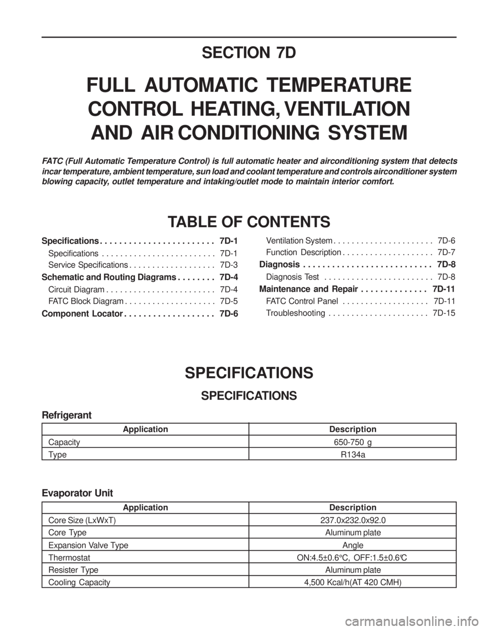
SECTION 7D
FULL AUTOMATIC TEMPERATURECONTROL HEATING, VENTILATION AND AIR CONDITIONING SYSTEM
Specifications . . . . . . . . . . . . . . . . . . . . . . . . 7D-1 Specifications . . . . . . . . . . . . . . . . . . . . . . . . . 7D-1
Service Specifications . . . . . . . . . . . . . . . . . . . 7D-3
Schematic and Routing Diagrams . . . . . . . . 7D-4
Circuit Diagram . . . . . . . . . . . . . . . . . . . . . . . . 7D-4
FATC Block Diagram . . . . . . . . . . . . . . . . . . . . 7D-5
Component Locator . . . . . . . . . . . . . . . . . . . 7D-6 TABLE OF CONTENTS
Ventilation System . . . . . . . . . . . . . . . . . . . . . . 7D-6
Function Description . . . . . . . . . . . . . . . . . . . . 7D-7
Diagnosis . . . . . . . . . . . . . . . . . . . . . . . . . . . 7D-8
Diagnosis Test . . . . . . . . . . . . . . . . . . . . . . . . 7D-8
Maintenance and Repair . . . . . . . . . . . . . . 7D-11 FATC Control Panel . . . . . . . . . . . . . . . . . . . 7D-11
Troubleshooting . . . . . . . . . . . . . . . . . . . . . . 7D-15
FATC (Full Automatic Temperature Control) is full automatic heater and airconditioning system that detects incar temperature, ambient temperature, sun load and coolant temperature and controls airconditioner system
blowing capacity, outlet temperature and intaking/outlet mode to maintain interior comfort.
SPECIFICATIONSSPECIFICATIONS
Application
Core Size (LxWxT)
Core Type
Expansion Valve Type Thermostat
Resister TypeCooling Capacity Description
237.0x232.0x92.0 Aluminum plate
Angle
ON:4.5±0.6 °C, OFF:1.5±0.6 °C
Aluminum plate
4,500 Kcal/h(AT 420 CMH)
Evaporator Unit
Application
Capacity
Type Description
650-750 g R134a
Refrigerant
Page 1160 of 1574
7D-4 FATC-HAVC
CIRCUIT DIAGRAM
SCHEMATIC AND ROUTING DIAGRAMS
Page 1161 of 1574
FATC-HAVC 7D-5
FATC BLOCK DIAGRAM
INCAR SENSOR
AMBIENT SENSOR
WATER TEMPERATURE SENSOR
SUN LOAD SENSOR
TEMPERATURE SWITCH
BLOWER SWITCH
MODE SWITCH
DEFROSTER SWITCH
INTAKE SWITCH
AUTO SWITCH
A/CON SWITCH
OFF SWITCH
TEMP DOOR POSITION FEEDBACKVOLTAGE
POWER TRANSISTOR COLLECTORVOLTAGE
VFD
MAX HI RELAY
POWER T/R
BLOWERMOTOR
ECUCOMPRESSOR
MIX ACTUATORMIX DOOR
INTAKE ACTUATORINTAKE DOOR
MODE ACTUATORMODE DOOR
Airconditioner output
C ON
T
RO L
UN I
T