Page 367 of 1574

1B3-102 OM600 ENGINE MECHANICAL
CheckingNotice The noise which continues short time during short travel (frequent starting of the engine) or engine starting after a long time storage is normal operating conditions. So, it doesnot need to be repaired. Determine the malfunctions in valveclearance compensation device with noise through following
tests. If defective, replace as respectively.
1. Run the engine at more than 3000rpm for approx. 4 minutes.
2. Stop the engine. After 5minutes, check the engine oil level and adjust if necessary.
3. Remove the cylinder head cover.
4. Check the valve tappets at TDC position of each cylinders.
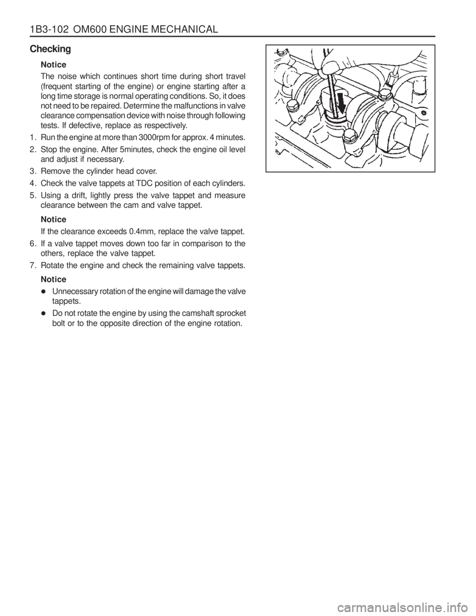
5. Using a drift, lightly press the valve tappet and measure clearance between the cam and valve tappet. Notice If the clearance exceeds 0.4mm, replace the valve tappet.
6. If a valve tappet moves down too far in comparison to the others, replace the valve tappet.
7. Rotate the engine and check the remaining valve tappets.
Notice
� Unnecessary rotation of the engine will damage the valve tappets.
� Do not rotate the engine by using the camshaft sprocket bolt or to the opposite direction of the engine rotation.
Page 533 of 1574

SECTION 1F1
M162 ENGINE CONTROLS
TABLE OF CONTENTS
CAUTION: Disconnect the negative battery cable before removing or installing any electrical unit or when a tool or equipment could easily come in contact with exposed electrical terminals. Disconnecting this cablewill help prevent personal injury and damage to the vehicle. The ignition must also be in LOCK unless otherwisenoted.
Specifications . . . . . . . . . . . . . . . . . . . . . . . 1F1-2
Fastener Tightening Specifications . . . . . . . . 1F1-2
Special Tools . . . . . . . . . . . . . . . . . . . . . . . 1F1-3 Special Tools Table . . . . . . . . . . . . . . . . . . . . 1F1-3
Schematic and Routing Diagrams . . . . . . . 1F1-4 E32 ECU (HFM) . . . . . . . . . . . . . . . . . . . . . . 1F1-4
E32 ECU (MSE) . . . . . . . . . . . . . . . . . . . . . . 1F1-5
Diagnosis . . . . . . . . . . . . . . . . . . . . . . . . . . 1F1-6
Self Diagnosis Socket Pin Numbers andDescriptions . . . . . . . . . . . . . . . . . . . . . . . . 1F1-6
Self Diagnosis Failure Code . . . . . . . . . . . . . 1F1-7
Test Box Connection . . . . . . . . . . . . . . . . . . 1F1-10
Fuel Injection System Test (MSE3.62) . . . . . 1F1-11
Ignition System Test . . . . . . . . . . . . . . . . . . 1F1-21
Idling Control and Electronic Pedal System Test . . . . . . . . . . . . . . . . . . . . . . . 1F1-26
Air Conditioner Control System Test . . . . . . 1F1-28
Fuel Pressure and Internal Leakage Test . . 1F1-29
Fuel Pump Test . . . . . . . . . . . . . . . . . . . . . . 1F1-31Injector Test . . . . . . . . . . . . . . . . . . . . . . . .
1F1-33
Maintenance and Repair . . . . . . . . . . . . . 1F1-35
On-Vehicle Service . . . . . . . . . . . . . . . . . . . . 1F1-35
ECU . . . . . . . . . . . . . . . . . . . . . . . . . . . . . . 1F1-35
Fuel Pressure Regulator . . . . . . . . . . . . . . 1F1-46
Fuel Distributor . . . . . . . . . . . . . . . . . . . . . . 1F1-50
Injector . . . . . . . . . . . . . . . . . . . . . . . . . . . . 1F1-54
Fuel Filter . . . . . . . . . . . . . . . . . . . . . . . . . . 1F1-57
Fuel Pump . . . . . . . . . . . . . . . . . . . . . . . . . 1F1-58
Purge Switchover Valve . . . . . . . . . . . . . . . 1F1-62
Vacuum System . . . . . . . . . . . . . . . . . . . . . 1F1-64
Crankshaft Position Sensor . . . . . . . . . . . . 1F1-65
Camshaft Position Sensor . . . . . . . . . . . . . 1F1-67
Hot Film Air Mass (HFM) Sensor . . . . . . . . . 1F1-69
Oxygen Sensor . . . . . . . . . . . . . . . . . . . . . . 1F1-72
Knock Sensor . . . . . . . . . . . . . . . . . . . . . . . 1F1-74
Coolant Temperature Sensor . . . . . . . . . . . 1F1-75
Accelerator Pedal Module . . . . . . . . . . . . . . 1F1-78
Page 560 of 1574

1F1-28 M162 ENGINE CONTROLS
AIR CONDITIONER CONTROL SYSTEM TEST
� 2.0
Engine:In idling
Air conditioner
switch : ON/OFF Air conditionerswitch : OFFAir conditionerswitch : ONCoolant temperature:above 105 °C
10 35
11 - 14 V 11 - 14 V
< 1 V
Condenser
fan(HI) control: Condenser fan
relay
Fan motor
ECU
Failure
code Item
�
1.0
Checking method
Engine:In idling
Air conditioner
switch : ON/OFF
Air conditioner switch : OFFAir conditionerswitch : ON
Te s t
stepRequirement
Specified value Possible cause
10 44 < 1 V
Air
conditioner signal:- Input signal (input signalfrom thermoamplifier)
44, 45,
11 - 14 V
� 5.1
Cable
Thermo amp
Auto amp
Dual pressure
switch
Air conditioner
control panel
� 1.1
Engine:In idling
Air conditioner
switch : ON/OFFAir conditionerswitch : OFFAir conditionerswitch:ON
10 27
< 1 V
Air
conditionercompressor:- Output signal
11 - 14 V
Thermo amp
Auto amp
Dual pressure
switch
Air conditioner
control panel
ECU
Page 570 of 1574
1F1-38 M162 ENGINE CONTROLS
Pin No.Abbreciation
Decription
21 222324252627282930313233343536373839404142434445464748495051525354555657585960 BRS
-----
KLIKU ---
GND
SP1+5V KP
TEV ML -
CAN L
CAN H -- - -
KPI
KLIMAKLIMA -
SP1SSP2S BLS
GND
SP2+2.5V S+BWA
S-B
KSK -
AUS
DIAG
V-SIG
TN-SIG
Brake switch-----Air conditioning clutch relay---Pedal potentiometer 1 groundPedal potentiometer 1 supplyFuel pump relay
Tank purge valveEngine fan (H1)-CAN-LowCAN-High-- - -Clutch switchAir conditioningElectronic traction signal-Pedal potentiometer 1 signalPedal potentiometer 2 signalBrake light switchPedal potentiometer 2 groundPedal potentiometer 2 supplyCruise accelerate/SetCruise resumeCruise decelerate/SetCruise safety contact switch-Cruise off switchDiagnostics (k-line)
Vehicle speed signalEngine speed signal
Page 573 of 1574
M162 ENGINE CONTROLS 1F1-41
Application
Pin No.Description
- Starter motor TM.50- - Electronic ground--- Lambda probe 1 heating Power ground TM.31
V-BATTERY TM.87
V-BATTERY TM.30Immobilizer crypto read Immobilizer crypto write -Lambda probe 1 groundLambda probe 1 signal- - -Brake switch-- - --Air conditioning clutch relay- - -1 23 4 5678 9
10 11
12 13 14 15161718 19 20212223 24 25262728 29 30-
TM.50 - -
GND - --
LSH1
TM.31TM.87TM.30
WFS I/O WFS O
-
GND LS1 - - -
BRS -- - --
KLIKU - - - -
� --
� -- -
�
�
�
�
�
� -
�
� - - -
� -- - --
� - - - -
� - -
� - --
�
�
�
�
�
�
-
�
� - - -
� -- - --
� - - -
� : Standard, �: Option Remarks
Abbreviation E32 ENG,
5speed M/T
E32 ENG,
4speed A/T (BTRA)
Page 574 of 1574
1F1-42 M162 ENGINE CONTROLS
Pin No.Description
Pedal potentiometer 1 ground Pedal potentiometer 1 supplyFuel pump relay
Tank purge valve Engine fan -CAN-LowCAN-High - - --Clutch switchAir conditioning Electronic traction signal(ABD) -Pedal potentiometer 1 signalPedal potentiometer 2 signalBrake light switchPedal potentiometer 2 ground Pedal potentiometer 2 supply Cruise accelerate/SetCruise resumeCruise decelerate/SetCruise safety contact switch - Cruise off switchDiagnostics(K-line)
Vehicle speed signalEngine speed signal31 323334 35 363738 39 40 41424344 45 4647484950 51 52535455 56 57585960GND
SP1+5V KP
TEV ML
-
CAN L
CAN H
- - --
KPL
KLIMA ETS
-
SP1SSP2S BLS
GND
SP2+2.5V
S+BWA
S-B
KSK -
AUS
DIAG
V-SIG
TN-SIG �
�
�
�
�
-
�
� - - --
� �
�
-
�
�
� �
�
�
�
�
� -
� �
�
� �
�
�
�
�
-
�
� - - --
� �
�
-
�
�
� �
�
�
�
�
� -
� �
�
� Remarks
Abbreviation E32 ENG,
5speed M/T
E32 ENG,
4speed A/T (BTRA)
Page 594 of 1574

1F1-62 M162 ENGINE CONTROLS
PURGE SWITCHOVER VALVE
1 Purge Switchover Valve
2 Line to Engine
3 Line to Canister
4 Canister
Functions The fuel vaporization control system is installed to inhibit the fuel vaporized gas from discharging into the atmosphere. Thefuel vaporized gas that is accumulated in the canister abstractsthrough the purge switchover valve purification during the engine combustion (except the decreasing mode) and coolant temperature of over 80 °C. For this reason, the ECU transacts
the engine speed, air inflow quantity, coolant temperature, andintake temperature. The purge switchover valve is activated by the ECU frequency according with the engine rotating speed to adjust the purification rate. The purification rate is determined by the continuous valve opening interval. The purge switchover valve is activated by the ECU for the following conditions :
� Coolant temperature of over 80 °C
� Engine speed of over 1000rpm
� 2 Minutes after starting
� When the fuel cut-off mode is not activated
Page 700 of 1574

SUSPENSION DIAGNOSIS 2A-3
DIAGNOSIS
GENERAL DIAGNOSIS
Checks
Loosened Mountings Damaged or Worn wheel BearingDamaged Shock Absorber
Damaged Tire Action
Retightening ReplaceReplaceReplace
Abnormal Noises
Checks
Broken Stabilizer Bar Faulty Shock Absorber Action
ReplaceReplace
Vehicle Rolling
Checks
Over Inflated Tire Faulty Shock Absorber Loosened wheel Nut Bent or Broken Coil Spring
Damaged TireWorn Bushing Action
Pressure Adjustment
Replace
Tighten as Specified ReplaceReplaceReplace
Poor Riding
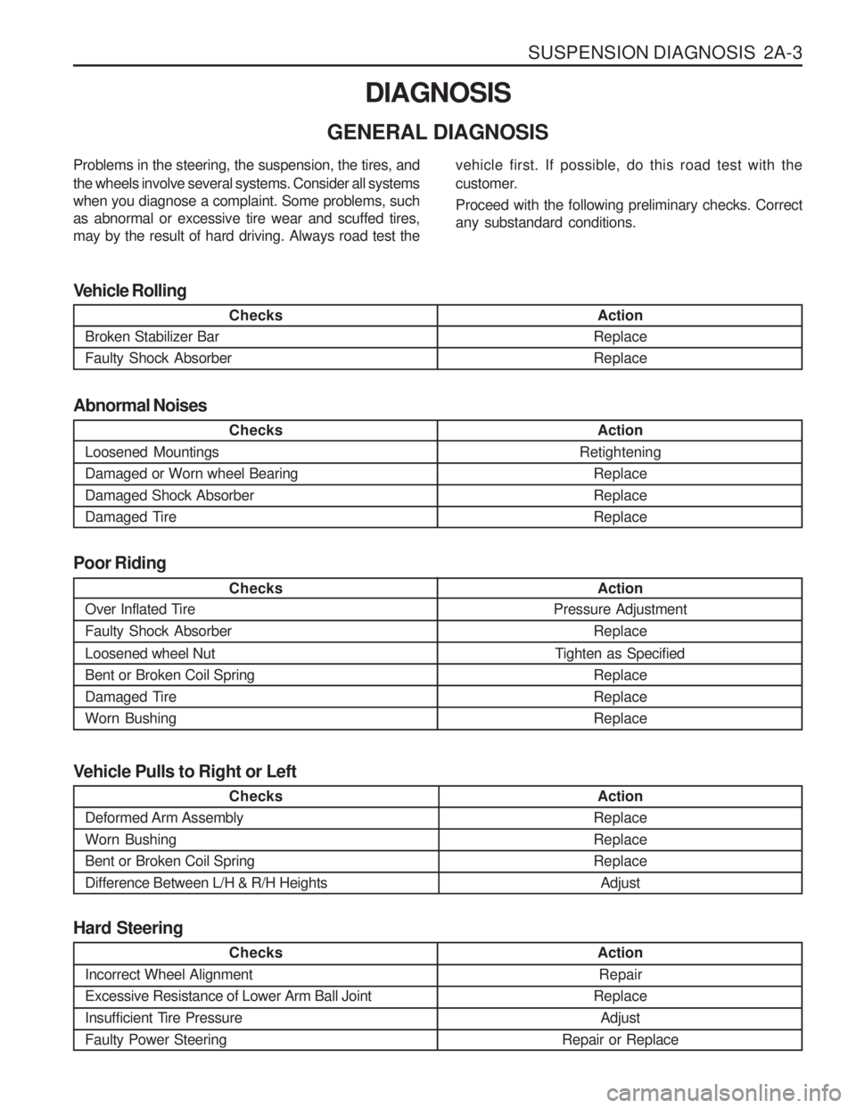
Problems in the steering, the suspension, the tires, and the wheels involve several systems. Consider all systems when you diagnose a complaint. Some problems, suchas abnormal or excessive tire wear and scuffed tires,may by the result of hard driving. Always road test the
vehicle first. If possible, do this road test with the
customer. Proceed with the following preliminary checks. Correct any substandard conditions.
Checks
Incorrect Wheel Alignment Excessive Resistance of Lower Arm Ball Joint
Insufficient Tire PressureFaulty Power Steering
Action Repair
Replace Adjust
Repair or Replace
Hard Steering
Checks
Deformed Arm Assembly Worn BushingBent or Broken Coil SpringDifference Between L/H & R/H Heights Action
ReplaceReplaceReplace Adjust
Vehicle Pulls to Right or Left