2003 SSANGYONG MUSSO air condition
[x] Cancel search: air conditionPage 1214 of 1574
9A-12 BODY WIRING SYSTEM
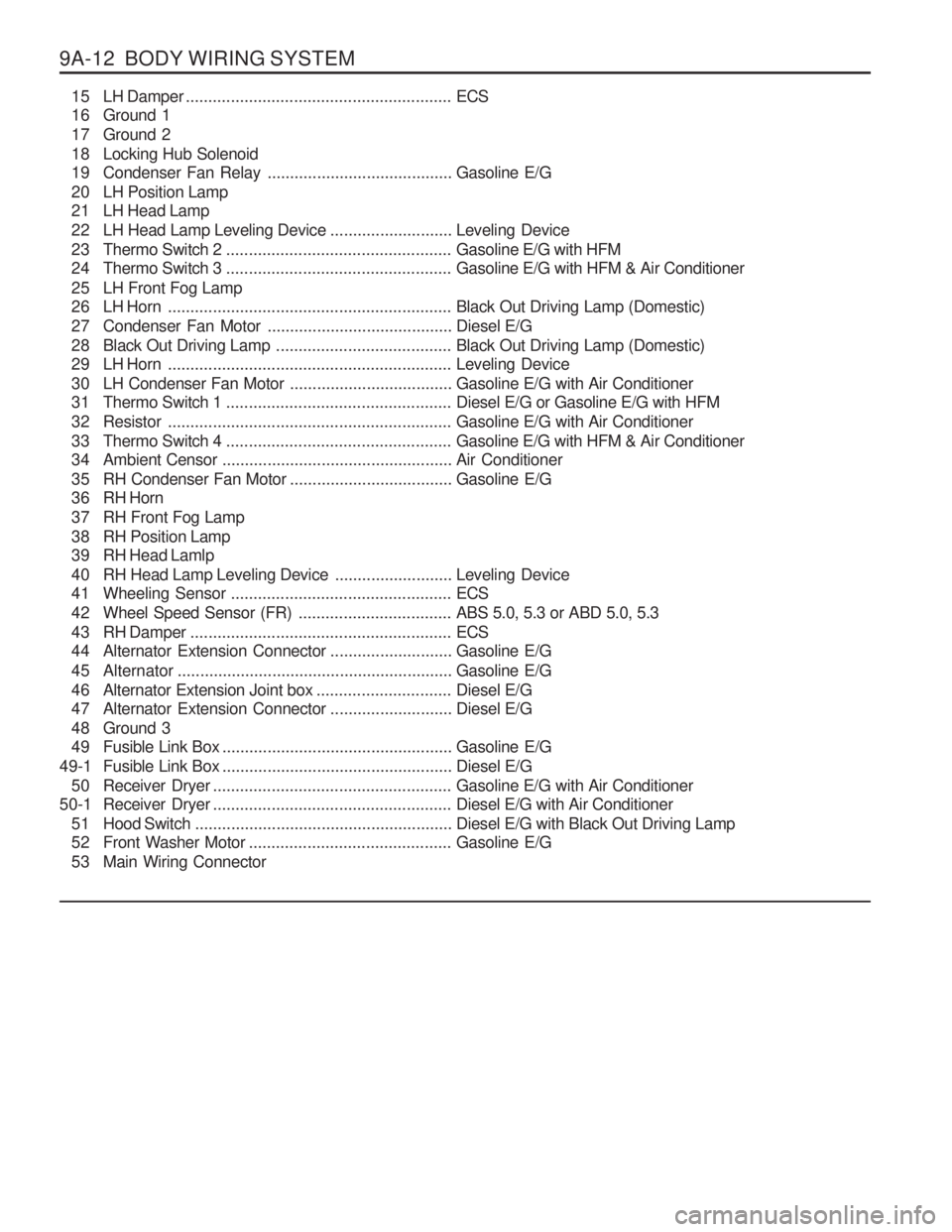
15 LH Damper........................................................... ECS
16 Ground 1
17 Ground 2
18 Locking Hub Solenoid
19 Condenser Fan Relay .........................................Gasoline E/G
20 LH Position Lamp
21 LH Head Lamp
22 LH Head Lamp Leveling Device ...........................Leveling Device
23 Thermo Switch 2 .................................................. Gasoline E/G with HFM
24 Thermo Switch 3 .................................................. Gasoline E/G with HFM & Air Conditioner
25 LH Front Fog Lamp
26 LH Horn ............................................................... Black Out Driving Lamp (Domestic)
27 Condenser Fan Motor .........................................Diesel E/G
28 Black Out Driving Lamp .......................................Black Out Driving Lamp (Domestic)
29 LH Horn ............................................................... Leveling Device
30 LH Condenser Fan Motor ....................................Gasoline E/G with Air Conditioner
31 Thermo Switch 1 .................................................. Diesel E/G or Gasoline E/G with HFM
32 Resistor ............................................................... Gasoline E/G with Air Conditioner
33 Thermo Switch 4 .................................................. Gasoline E/G with HFM & Air Conditioner
34 Ambient Censor ................................................... Air Conditioner
35 RH Condenser Fan Motor ....................................Gasoline E/G
36 RH Horn
37 RH Front Fog Lamp
38 RH Position Lamp
39 RH Head Lamlp
40 RH Head Lamp Leveling Device ..........................Leveling Device
41 Wheeling Sensor ................................................. ECS
42 Wheel Speed Sensor (FR) ..................................ABS 5.0, 5.3 or ABD 5.0, 5.3
43 RH Damper .......................................................... ECS
44 Alternator Extension Connector ...........................Gasoline E/G
45 Alternator ............................................................. Gasoline E/G
46 Alternator Extension Joint box ..............................Diesel E/G
47 Alternator Extension Connector ...........................Diesel E/G
48 Ground 3
49 Fusible Link Box ................................................... Gasoline E/G
49-1 Fusible Link Box ................................................... Diesel E/G
50 Receiver Dryer ..................................................... Gasoline E/G with Air Conditioner
50-1 Receiver Dryer ..................................................... Diesel E/G with Air Conditioner
51 Hood Switch ......................................................... Diesel E/G with Black Out Driving Lamp
52 Front Washer Motor ............................................. Gasoline E/G
53 Main Wiring Connector
Page 1220 of 1574
9A-18 BODY WIRING SYSTEM
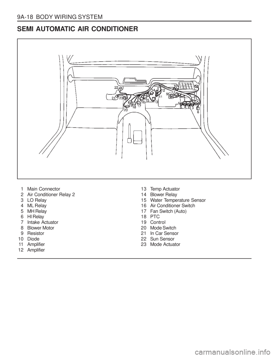
SEMI AUTOMATIC AIR CONDITIONER1 Main Connector
2 Air Conditioner Relay 2
3 LO Relay
4 ML Relay
5 MH Relay
6 HI Relay
7 Intake Actuator
8 Blower Motor
9 Resistor
10 Diode 11 Amplifier
1 2 Amplifier 13 Temp Actuator
14 Blower Relay
15 Water Temperature Sensor
16 Air Conditioner Switch
17 Fan Switch (Auto)
18 PTC
19 Control
20 Mode Switch
21 In Car Sensor
22 Sun Sensor
23 Mode Actuator
Page 1221 of 1574
BODY WIRING SYSTEM 9A-19
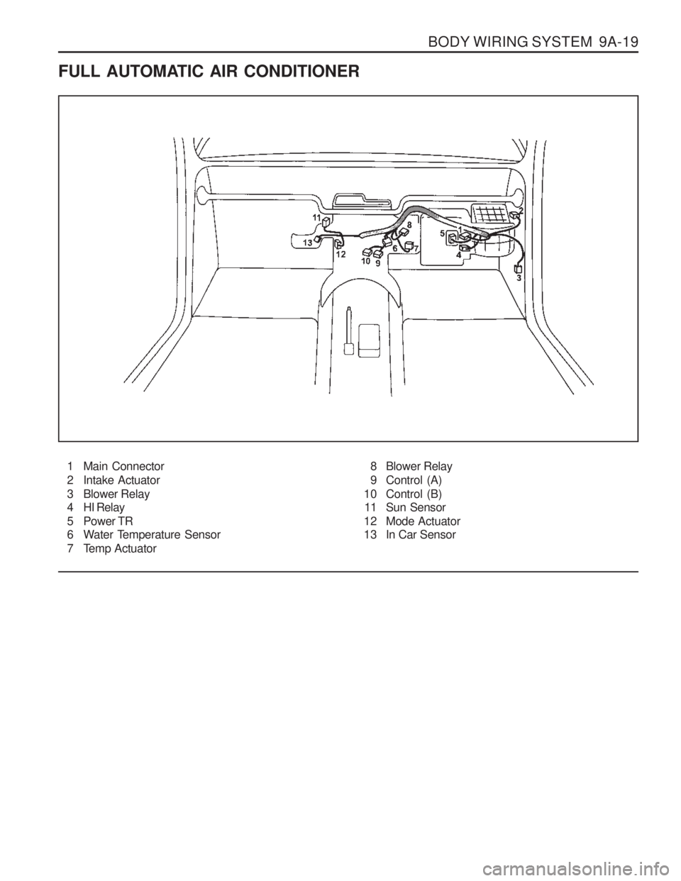
FULL AUTOMATIC AIR CONDITIONER1 Main Connector
2 Intake Actuator
3 Blower Relay
4 HI Relay
5 Power TR
6 Water Temperature Sensor
7 Temp Actuator 8 Blower Relay
9 Control (A)
10 Control (B) 11 Sun Sensor
12 Mode Actuator
13 In Car Sensor
Page 1315 of 1574
MUSSO-SPORTS 1A-3
SUPPLEMENT
HUBER EGR
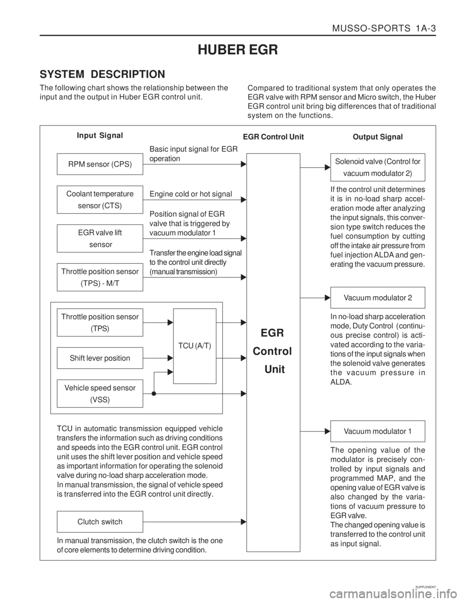
SYSTEM DESCRIPTION The following chart shows the relationship between the input and the output in Huber EGR control unit. Compared to traditional system that only operates theEGR valve with RPM sensor and Micro switch, the HuberEGR control unit bring big differences that of traditionalsystem on the functions.
Input Signal
RPM sensor (CPS)
EGR valve lift sensor
Throttle position sensor (TPS) - M/T
Shift lever position
Throttle position sensor (TPS)
Vehicle speed sensor(VSS) Basic input signal for EGR operation Engine cold or hot signal
Position signal of EGR valve that is triggered by vacuum modulator 1 Transfer the engine load signal to the control unit directly (manual transmission)
TCU (A/T)
EGR
Control
Unit
Coolant temperature sensor (CTS)
Solenoid valve (Control forvacuum modulator 2)
If the control unit determines it is in no-load sharp accel- eration mode after analyzing the input signals, this conver- sion type switch reduces the fuel consumption by cutting off the intake air pressure from
fuel injection ALDA and gen- erating the vacuum pressure. In no-load sharp acceleration
mode, Duty Control ( continu- ous precise control) is acti- vated according to the varia- tions of the input signals when the solenoid valve generates the vacuum pressure in ALDA.
Vacuum modulator 2
The opening value of the modulator is precisely con- trolled by input signals and programmed MAP, and the opening value of EGR valve is also changed by the varia- tions of vacuum pressure to EGR valve. The changed opening value is transferred to the control unit as input signal.
Vacuum modulator 1
TCU in automatic transmission equipped vehicle transfers the information such as driving conditions and speeds into the EGR control unit. EGR control unit uses the shift lever position and vehicle speed as important information for operating the solenoid valve during no-load sharp acceleration mode. In manual transmission, the signal of vehicle speed is transferred into the EGR control unit directly.
Clutch switch
In manual transmission, the clutch switch is the one of core elements to determine driving condition. Output Signal
EGR Control Unit
Page 1357 of 1574
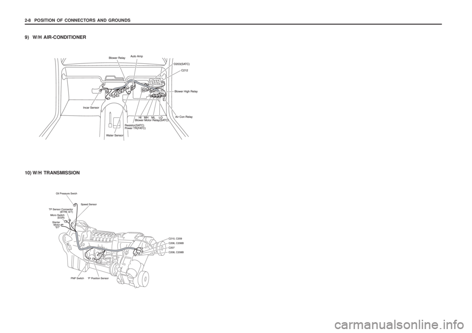
2-8 POSITION OF CONNECTORS AND GROUNDS
10) W/H TRANSMISSION
9) W/H AIR-CONDITIONER
Page 1372 of 1574
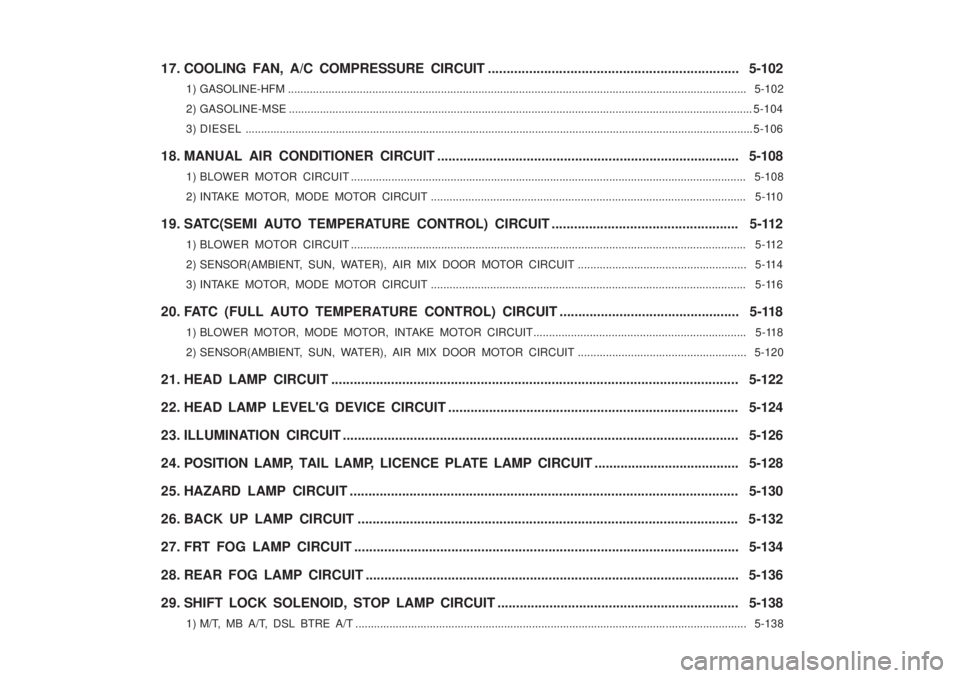
17. COOLING FAN, A/C COMPRESSURE CIRCUIT................................................................... 5-102
1) GASOLINE-HFM ................................................................................................................. .................................. 5-102
2) GASOLINE-MSE ..................................................................................................................................................... 5-104
3) DIESEL ................................................................................................................................................................... 5-106
18. MANUAL AIR CONDITIONER CIRCUIT ................................................................................. 5-108
1) BLOWER MOTOR CIRCUIT ............................................................................................................................... 5-108
2) INTAKE MOTOR, MODE MOTOR CIRCUIT ............................................................................................. ........ 5-110
19. SATC(SEMI AUTO TEMPERATURE CONTROL) CIRCUIT .................................................. 5-112 1) BLOWER MOTOR CIRCUIT ............................................................................................................................... 5-112
2) SENSOR(AMBIENT, SUN, WATER), AIR MIX DOOR MOTOR CIRCUIT ...................................................... 5-114
3) INTAKE MOTOR, MODE MOTOR CIRCUIT ............................................................................................. ........ 5-116
20. FATC (FULL AUTO TEMPERATURE CONTROL) CIRCUIT ................................................ 5-118 1) BLOWER MOTOR, MODE MOTOR, INTAKE MOTOR CIRCUIT.................................................................... 5-118
2) SENSOR(AMBIENT, SUN, WATER), AIR MIX DOOR MOTOR CIRCUIT ...................................................... 5-120
21. HEAD LAMP CIRCUIT ........................................................................................................... .. 5-122
22. HEAD LAMP LEVEL'G DEVICE CIRCUIT .............................................................................. 5-124
23. ILLUMINATION CIRCUIT ........................................................................................................ .. 5-126
24. POSITION LAMP, TAIL LAMP, LICENCE PLATE LAMP CIRCUIT ....................................... 5-128
25. HAZARD LAMP CIRCUIT ........................................................................................................ 5-130
26. BACK UP LAMP CIRCUIT ...................................................................................................... 5 -132
27. FRT FOG LAMP CIRCUIT ....................................................................................................... 5-134
28. REAR FOG LAMP CIRCUIT .................................................................................................... 5- 136
29. SHIFT LOCK SOLENOID, STOP LAMP CIRCUIT ................................................................. 5-138
1) M/T, MB A/T, DSL BTRE A/T .................................................................................................... .......................... 5-138
Page 1474 of 1574
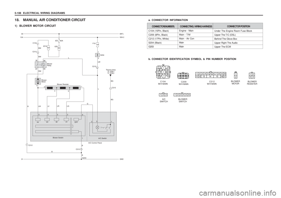
5-108 ELECTRICAL WIRING DIAGRAMS
18. MANUAL AIR CONDITIONER CIRCUIT
1) BLOWER MOTOR CIRCUIT
C104
W/H MAIN
1452
8
14
79
3
15131011
6
12
Engine - Main Main - T/M Main - Air Con MainMain
C104 (15Pin, Black)C209 (8Pin, Black) C212 (17Pin, White) S204 (Black) G203
b. CONNECTOR IDENTIFICATION SYMBOL & PIN NUMBER POSITION
a. CONNECTOR INFORMATION
CONNECTOR(NUMBER)
CONNECTING. WIRING HARNESSCONNECTOR POSITION
Under The Engine Room Fuse Block Upper The T/C (DSL) Behind The Glove BoxUpper Right The Audio Upper The ECM
C212
W/H MAIN
12345 678910
11 12 13 14 15 16 17
BLOWER MOTOR
1 212
34
123456
BLOWER
RESISTER
BLOWER SWITCH
123
A/C
SWITCH C209
W/H MAIN
1234
5678
Blower
Relay
30 86
87 85
E
f9
60AEf18
30A2
C104
14
C212
G203
BW
BW
L
M
1
2 RW
LW LY LR LG
Blower Motor
Blower Resister
B
L
2
4 31
15
C212
17
C212
F19
10A
1
2 S204
LW
16
C212
B
B B
54
#4 3
#3 2
6
2
#2 #1
1
OFF
Blower Switch
A/C Switch
A/C Control Panal
G
3 1
11C212
BG BG
Thermo Amp
"3" (GSL)"2" (DSL)
30 BAT+
15A IGN 2
31 GND
Ef2 80A