2003 SSANGYONG MUSSO service indicator
[x] Cancel search: service indicatorPage 12 of 1574

0B-12 GENERAL INFORMATIONOWNER INSPECTIONS AND SERVICES
WHILE OPERATING THE VEHICLE Horn Operation Blow the horn occasionally to make sure it works. Check all the button locations. Brake System Operation Be alert for abnormal sounds, increased brake pedal travel or repeated puling to one side when braking. Also, if the brake warning light goes on, or flashes, something may be wrong with part of the brake system. Exhaust System Operation Be alert to any changes in the sound of the system or the smell of the fumes. These are signs that the system may be leaking or overheating. Have the system
inspected and repaired immediately. Tires, Wheels and Alignment Operation Be alert to any vibration of the steering wheel or the seats at normal highway speeds. This may mean a wheelneeds to be balanced. Also, a pull right or left on a straight, level road may show the need for a tire pressure adjustment or a wheel alignment. Steering System Operation Be alert to changes in the steering action. An inspection is needed when the steering wheel is hard to turn or
has too much free play, or is unusual sounds are noticedwhen turning or parking. Headlight Aim
Take note of the light pattern occasionally. Adjust the headlights if the beams seem improperly aimed.
AT EACH FUEL FILL A fluid loss in any (except windshield washer) system may indicate a problem. Have the system inspected and
repaired immediately. Engine Oil Level
Check the oil level and add oil if necessary. The best time to check the engine oil level is when the oil is warm.
1. After stopping the engine, wait a few minutes for the oil to drain back to the oil pan.
2. Pull out the oil level indicator (dip stick).
3. Wipe it clean, and push the oil level indicator back down all the way.
4. Pull out the oil level indicator and look at the oil level on it. 5. Add oil, if needed, to keep the oil level above the
lower mark. Avoid overfilling the engine, since this may cause engine damage.
6. Push the indicator all the way back down into the engine after taking the reading.
If you check the oil level when the oil is cold, do not runthe engine first. The cold oil will not drain back to the pan fast enough to give a true oil level reading. Engine Coolant Level and Condition Check the coolant level in the coolant reservoir tank
and add coolant if necessary. Inspect the coolant. Replace dirty or rusty coolant.
Windshield Washer Fluid Level
Check the washer fluid level in the reservoir. Add fluid if
necessary.
AT LEAST TWICE A MONTH Tire And Wheel Inspection and Pressure Check Check the tire for abnormal wear or damage. Also check for damaged wheels. Check the tire pressure when the tires are cold ( check the spare also, unless it is astowaway). Maintain the recommended pressures. Refer
to “Tire and Wheel” is in section 0B.
AT LEAST MONTHLY Light Operation Check the operation of the license plate light, the headlights (including the high beams), the parking lights,the fog lights, the taillight, the brake lights, the turn
signals, the backup lights and the hazard warning flasher. Fluid Leak Check Periodically inspect the surface beneath the vehicle for
water, oil, fuel or other fluids, after the vehicle has been
parked for a while. Water dripping from the air conditioning system after use is normal. If you notice fuel leaks or fumes, find the cause and correct it at once.
AT LEAST TWICE A YEAR Power Steering System Reservoir Level Check the power steering fluid level. Keep the power steering fluid at the proper level. Refer to Section 6A,
Power Steering System. Brake Master Cylinder Reservoir Level Check the fluid and keep it at the proper level. A low fluid level can indicate worn disc brake pads which mayneed to be serviced. Check the breather hole in the reservoir cover to be free from dirt and check for an open passage.
Page 748 of 1574

TIRES AND WHEELS 2E-5
MAINTENANCE AND REPAIR ON-VEHICLE SERVICE WHEELS AND TIRES Removal & Installation Procedure
1. Inspection of tireCheck tread area for tread surface, crack, damage by nail
in or stones. Replace or repair if necessary.
� Replace the tire if tread-wear indicator of the tread
grooves appears where marked ' ' .
� The wear limit of snow tire is the same as normal tire
(1.6mm) and indicator location is marked ' �'.
Limit 1.6mm
Standard
2.66mm
Standard
2.03mm
2. Wear limit.
3. Runout measurement.
� Excessive runout of tires and wheels can cause the
abnormal wear of tire. Using a dial indicator, measure wheel and tire runout.
� Measure radial runout at the rim flange and center of
the tire tread area.
� Measure lateral runout at the tire bead area of the wheel
and tire sidewall. Notice
If runout is excessive, replace the tire or wheel.
Page 840 of 1574

ANTILOCK BRAKE SYSTEM 4F-11
ABS, ABS/ABD 5.0 Initializing
1. Set the ignition switch n “ON ” position.
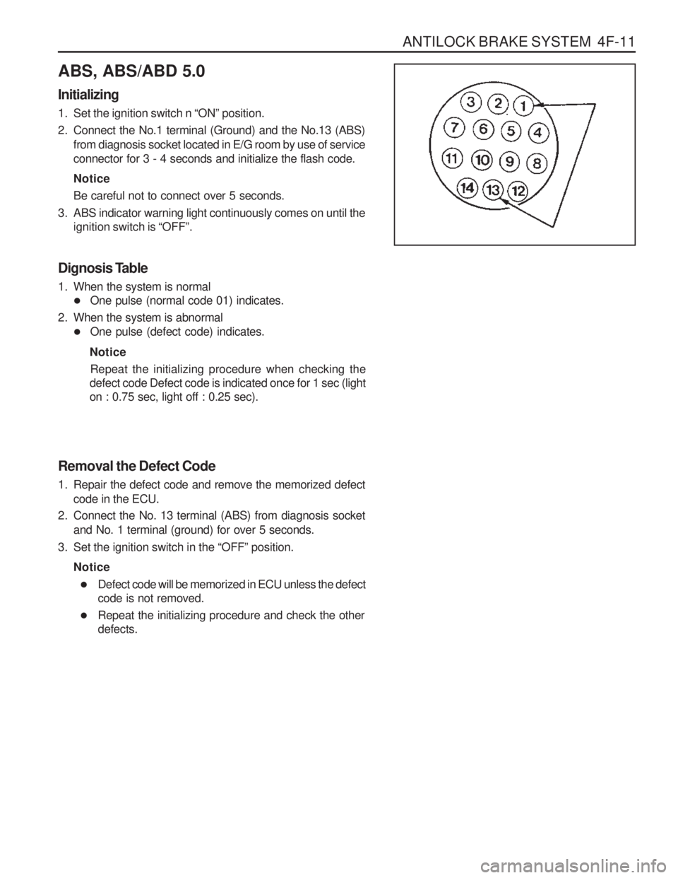
2. Connect the No.1 terminal (Ground) and the No.13 (ABS) from diagnosis socket located in E/G room by use of service connector for 3 - 4 seconds and initialize the flash code. Notice Be careful not to connect over 5 seconds.
3. ABS indicator warning light continuously comes on until the ignition switch is “OFF ”.
Dignosis Table
1. When the system is normal � One pulse (normal code 01) indicates.
2. When the system is abnormal � One pulse (defect code) indicates.
Notice Repeat the initializing procedure when checking the
defect code Defect code is indicated once for 1 sec (light on : 0.75 sec, light off : 0.25 sec).
Removal the Defect Code
1. Repair the defect code and remove the memorized defect code in the ECU.
2. Connect the No. 13 terminal (ABS) from diagnosis socket and No. 1 terminal (ground) for over 5 seconds.
3. Set the ignition switch in the “OFF ” position.
Notice � Defect code will be memorized in ECU unless the defect code is not removed.
� Repeat the initializing procedure and check the otherdefects.
Page 858 of 1574

PARKING BRAKE 4G-3
MAINTENANCE AND REPAIR ON-VEHICLE SERVICE PARKING BRAKE Removal & Installation Procedure
1. Disconnect the parking brake indicator switch connector.
2. Disconnect the right and left cable from equalizer whileparking brake lever is released.
3. Unscrew 8 bolts and remove the parking brake lever assembly. Installation Notice Notice
Tighten the bolts with sequence number while the lever is pulled up 4 to 6 notches.
Tightening Torque 8 - 18 Nm
4. Unscrew the frame and lower arm side cable mounting bracket bolts. Installation Notice
Tightening Torque 8 - 18 Nm
Page 1056 of 1574

5D1-4 TRANSFER CASE (PART TIME 4408)SELF-DIAGNOSIS
SYSTEM DESCRIPTION
1. TCCU detects transfer case system malfunctions and indicates malfunctioning part(s) through flashing 4H,4L indicator lights.
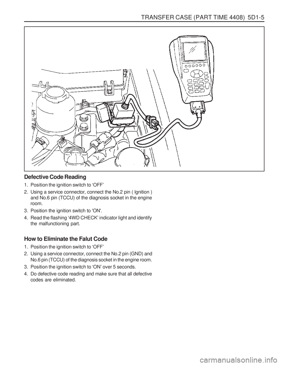
Using a service connector, connect it to the diagnosis box in the engine room and read the flashing of the ‘4WD
CHECK ’ indicator light.
The flashing indicator light will show you defective code(s).
2. Identify 7 defective codes after reading the flashing indicator light.
� TCCU
� Shift motor
� Magnetic synchronizer clutch
� Speed sensor
� Hub solenoid
� Selector switch
� Motor position sensor
3. Transfer case system is malfunctioning when: � 4H ,4L indicator lights are remain on after 0.6 second when turning the ignition switch ‘ON ’
� 4H,4L indicator lights are continuously come on during driving.
4. If only 1 part is malfunctioning, ‘4WD CHECK ’ indicator light
will display defective code 3 times continuously.
5. If more then 2 part is malfunctioning, the first malfunctioning part will be displayed 3 times and following malfunctioningparts will be displayed .
6. To read defective code, connect the service connector and turn the ignition switch 'ON'.
7. After repairing, eliminate the defective code stored in the TCCU. NoticeBefore replacing the malfunction parts with defective code, check the wires and connectors for proper condition.
Page 1057 of 1574

TRANSFER CASE (PART TIME 4408) 5D1-5
Defective Code Reading
1. Position the ignition switch to ‘OFF ’
2. Using a service connector, connect the No.2 pin ( lgnition ) and No.6 pin (TCCU) of the diagnosis socket in the engine room.
3. Position the ignition switch to 'ON'.
4. Read the flashing ‘4WD CHECK ’ indicator light and identify
the malfunctioning part.
How to Eliminate the Falut Code
1. Position the ignition switch to ‘OFF ’
2. Using a service connector, connect the No.2 pin (GND) and No.6 pin (TCCU) of the diagnosis socket in the engine room.
3. Position the ignition switch to ‘ON ’ over 5 seconds.
4. Do defective code reading and make sure that all defective codes are eliminated.
Page 1058 of 1574

5D1-6 TRANSFER CASE (PART TIME 4408)
Diagnostic Table
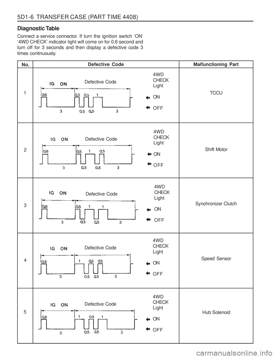
Connect a service connector. If turn the ignition switch ‘ON ’
‘ 4WD CHECK ’ indicator light will come on for 0.6 second and
turn off for 3 seconds and then display a defective code 3
times continuously.
No. Defective Code
Malfunctioning Part
1
2 3 4
5 TCCU
Shift Motor
Synchronizer Clutch
Speed SensorHub Solenoid
4WD CHECK Light ON OFF
Defective Code
4WD CHECK Light ON OFF
Defective Code
4WD CHECKLight ONOFF
Defective Code
4WD CHECKLight ONOFF
Defective Code
4WD CHECK Light ONOFF
Defective Code