Page 1240 of 1574
9B-12 LIGHTING SYSTEM
Tail/stop and turn signal lamp
Tail/stop Lamp and backup lamp
Rear Combination Lamp Removal & Installation Procedure
1. Open the tailgate and remove the inner cover of the rear
combination lamp.
2. Unscrew 4(8mm) nuts of tail/stop lamp and turn signal lamp assembly.
3. Unscrew 6(8mm) nuts of tail/stop lamp and back-up lamp assembly.
4. Disconnect each connectors and remove the rear combination lamp. Replace with specified bulb, if
necessary. NoticeRefer to lamp specification.
Page 1248 of 1574
9D-6 WIPERS/WASHER SYSTEM
Removal & Installation Procedure
1. Remove the spare tire.
2. Unscrew the locking nut and remove the wiper.
3. Unscrew the locking nut of wiper motor.
4. Remove the tailgate trim panel.
5. Dieconnect the connector from the wiper motor.
6. Unscrew four screws(arrows) and remove the wiper motor.
Page 1252 of 1574
INSTRUMENTATION/DRIVER INFORMATION 9E-3
COMBINATION METER
COMPONENT LOCATOR
1. Speedometer
2. Odometer
3. Trip odometer
4. Tachometer
5. Coolant temperature gauge
6. Fuel gauge
7. Low fuel level warning light
8. Turn signal indicator (left)
9. Turn signal indicator (right)
10. Outside rearview mirror & tailgate heating switch
11. Reset button
12. Auto shift indicator*
13. Door open warning light
14. TCS indicator (equipped with ABD)*
21. ABS warning light* 22. EBD warning light*
23. ECS / SPORT warning light*
24. 4 - wheel warning light*
25. 4 - wheel high indicator
26. 4 - wheel low indicator
27. WINTER indicator
28. POWER indicator
29. High beam indicator
15. Alternator warning light
16. Engine oil pressure warning light
17. Brake system warning light
18. Glow indicator light (For Diesel engine)
19. Airbag warning light*
20. Seat belt reminder
Page 1267 of 1574
SECTION 9L
GLASS AND MIRRORS
Caution: Disconnect the negative battery cable before removing or installing any electrical unit or when a tool or equipment could easily come in contact with exposed electrical terminals. Disconnecting this cable will help prevent personal injury and damage to the vehicle. The ignition must also be in LOCK unless otherwisenoted.TABLE OF CONTENTS
Schematic and Routing Diagrams . . . . . . . . 9L-2 Outside Mirror . . . . . . . . . . . . . . . . . . . . . . . . . 9L-2
Auto Dimming Room Mirror . . . . . . . . . . . . . . . 9L-3
Maintenance and Repair . . . . . . . . . . . . . . . 9L-4 On-Vehicle Service . . . . . . . . . . . . . . . . . . . . . .
9L-4
Front & Side Glass . . . . . . . . . . . . . . . . . . . . . 9L-4
Tailgate Glass . . . . . . . . . . . . . . . . . . . . . . . . . 9L-9
Auto Dimming Room Mirror . . . . . . . . . . . . . . 9L-12
Page 1275 of 1574
GLASS AND MIRRORS 9L-9
TAILGATE GLASS
1 Wiper Arm and Blade Assembly
2 Heating Lines3 Tailgate Trim
4 Tailgate Glass
Notice Removal and installation is as shown in upper drawings.
Page 1276 of 1574

9L-10 GLASS AND MIRRORS
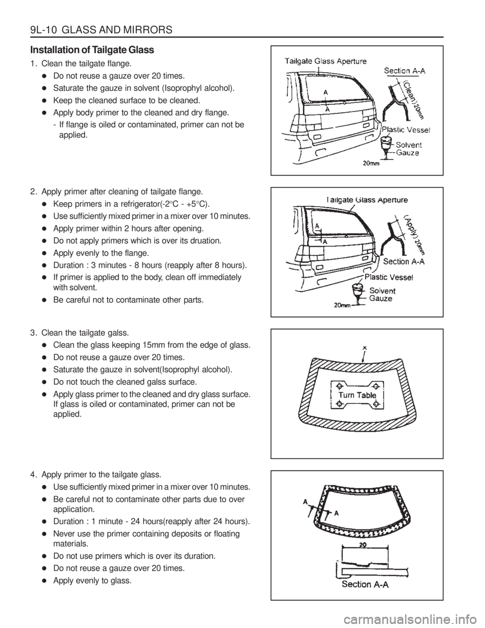
Installation of Tailgate Glass
1. Clean the tailgate flange.� Do not reuse a gauze over 20 times.
� Saturate the gauze in solvent (Isoprophyl alcohol).
� Keep the cleaned surface to be cleaned.
� Apply body primer to the cleaned and dry flange.
- If flange is oiled or contaminated, primer can not be
applied.
2. Apply primer after cleaning of tailgate flange. � Keep primers in a refrigerator(-2 °C - +5 °C).
� Use sufficiently mixed primer in a mixer over 10 minutes.
� Apply primer within 2 hours after opening.
� Do not apply primers which is over its druation.
� Apply evenly to the flange.
� Duration : 3 minutes - 8 hours (reapply after 8 hours).
� If primer is applied to the body, clean off immediately with solvent.
� Be careful not to contaminate other parts.
3. Clean the tailgate galss. � Clean the glass keeping 15mm from the edge of glass.
� Do not reuse a gauze over 20 times.
� Saturate the gauze in solvent(Isoprophyl alcohol).
� Do not touch the cleaned galss surface.
� Apply glass primer to the cleaned and dry glass surface. If glass is oiled or contaminated, primer can not beapplied.
4. Apply primer to the tailgate glass. � Use sufficiently mixed primer in a mixer over 10 minutes.
� Be careful not to contaminate other parts due to overapplication.
� Duration : 1 minute - 24 hours(reapply after 24 hours).
� Never use the primer containing deposits or floatingmaterials.
� Do not use primers which is over its duration.
� Do not reuse a gauze over 20 times.
� Apply evenly to glass.
Page 1277 of 1574
GLASS AND MIRRORS 9L-11
5. Apply sealant to the glass.� Turn over the glass and apply sealant.
� Uneven application of sealant may cause water leakage after installation of glass.
� Do not touch the glass moldings and dam rubber whileapplying sealant.
6. Using suction holders, install the tailgate glass within
5minutes after application of sealant.
� Fix the glass with adhesive tape.
� Apply sealant additionally between the quarter outer panel and tailgate glass moldings.
Page 1288 of 1574
BUMPERS AND FASCIAS 9O-5
Mounting Inspection
1. Clearance between the upper bumper facia and tailgate.
2. Clearance between the rear bumper facia and rear bumpermolding.
Clearance 12 ± 1.0 mm
Clearance 11.0 mm
3. Clearance between the quarter outer panel and rear
bumper facia.
Clearance 10.0 mm