Page 344 of 4179
![NISSAN X-TRAIL 2003 Service Repair Manual CO-12
[QR]
RADIATOR
RADIATORPFP:21400
Removal and InstallationEBS00KOI
WARNING:
Do not remove radiator cap when the engine is hot. Serious burns could occur from high-pressure
engine coolant escapin](/manual-img/5/57404/w960_57404-343.png "NISSAN X-TRAIL 2003 Service Repair Manual CO-12
[QR]
RADIATOR
RADIATORPFP:21400
Removal and InstallationEBS00KOI
WARNING:
Do not remove radiator cap when the engine is hot. Serious burns could occur from high-pressure
engine coolant escapin")
CO-12
[QR]
RADIATOR
RADIATORPFP:21400
Removal and InstallationEBS00KOI
WARNING:
Do not remove radiator cap when the engine is hot. Serious burns could occur from high-pressure
engine coolant escaping from radiator. Wrap a thick cloth around the cap. Slowly turn it a quarter of a
turn to release built-up pressure. Carefully remove radiator cap by turning it all the way.
REMOVAL
1. Remove RH and LH undercovers.
2. Drain engine coolant. Refer to CO-9, "
Changing Engine Coolant" .
CAUTION:
�Perform this step when engine is cold.
�Do not spill engine coolant on drive belt.
3. Remove air duct (inlet) and air duct assembly. Refer to EM-15, "
AIR CLEANER AND AIR DUCT" .
4. Disconnect harness connector from fan motor, and move it aside.
5. Disconnect radiator hoses (upper and lower).
6. Remove A/T fluid cooler hoses. (A/T models)
�Install blind plug to avoid leakage of A/T fluid.
7. Remove radiator mounting brackets.
8. Remove radiator and radiator cooling fan assembly.
CAUTION:
Do not damage or scratch radiator core when removing.
1. Reservoir tank 2. Reservoir tank cap 3. Reservoir tank hose
4. Radiator mounting bracket 5. Mounting rubber (upper) 6. Radiator cap
7. Radiator 8. O-ring 9. Radiator drain plug
10. Mounting rubber (lower) 11. A/T fluid cooler hose 12. Radiator hose (lower)
13. Radiator hose (upper) 14. Bracket 15. Radiator cooling fan assembly
PBIC2251E
Page 345 of 4179
![NISSAN X-TRAIL 2003 Service Repair Manual RADIATOR
CO-13
[QR]
C
D
E
F
G
H
I
J
K
L
MA
CO
INSTALLATION
Install in the reverse order of removal.
INSPECTION AFTER INSTALLATION
�Check for leaks of engine coolant using a radiator cap tester adapt](/manual-img/5/57404/w960_57404-344.png "NISSAN X-TRAIL 2003 Service Repair Manual RADIATOR
CO-13
[QR]
C
D
E
F
G
H
I
J
K
L
MA
CO
INSTALLATION
Install in the reverse order of removal.
INSPECTION AFTER INSTALLATION
�Check for leaks of engine coolant using a radiator cap tester adapt")
RADIATOR
CO-13
[QR]
C
D
E
F
G
H
I
J
K
L
MA
CO
INSTALLATION
Install in the reverse order of removal.
INSPECTION AFTER INSTALLATION
�Check for leaks of engine coolant using a radiator cap tester adapter (special service tool: EG17650301)
and a radiator cap tester (commercial service tool). Refer to CO-9, "
LEAK CHECK" .
�Start and warm up engine. Visually check if there is no leaks of engine coolant and A/T fluid (A/T models).
Checking Radiator CapEBS00KOK
1. Pull negative-pressure valve to open it and make sure that it
closes completely when released.
�Make sure that there is no dirt or damage on the valve seat of
radiator cap negative-pressure valve.
�Make sure that there are no unusualness in the opening and
closing conditions of negative-pressure valve.
2. Check radiator cap relief pressure.
�When connecting radiator cap to radiator cap tester (commer-
cial service tool) and radiator cap tester adapter (special ser-
vice tool), apply engine coolant to radiator cap seal surface.
�Replace radiator cap if there is an unusualness in negative-
pressure valve, or if the relief pressure falls below the limit.
Checking RadiatorEBS00KOL
Check radiator for mud or clogging. If necessary, clean radiator as follows.
�Be careful not to bend or damage radiator fins.
�When radiator is cleaned without removal, remove all surrounding parts such as cooling fan, radiator
shroud and horns. Then tape harness and connectors to prevent water from entering.
1. Apply water by hose to the back side of the radiator core vertically downward.
2. Apply water again to all radiator core surface once per minute.
3. Stop washing if any stains no longer flow out from the radiator.
4. Blow air into the back side of radiator core vertically downward.
�Use compressed air lower than 490 kPa (4.9 bar, 5 kg/cm2 , 71 psi) and keep distance more than 30 cm
(11.8 in).
5. Blow air again into all the radiator core surfaces once per minute until no water sprays out.
SMA967B
Standard:
78 - 98 kPa (0.78 - 0.98 bar, 0.8 - 1.0 kg/cm
2 , 11 - 14 psi)
Limit:
59 kPa (0.59 bar, 0.6 kg/cm
2 , 9 psi)
SLC135B
Page 350 of 4179
![NISSAN X-TRAIL 2003 Service Repair Manual CO-18
[QR]
COOLING FAN
COOLING FANPFP:21140
Removal and InstallationEBS011TD
REMOVAL
1. Drain engine coolant from radiator. Refer to CO-9, "Changing Engine Coolant" .
CAUTION:
�Perform this step wh](/manual-img/5/57404/w960_57404-349.png "NISSAN X-TRAIL 2003 Service Repair Manual CO-18
[QR]
COOLING FAN
COOLING FANPFP:21140
Removal and InstallationEBS011TD
REMOVAL
1. Drain engine coolant from radiator. Refer to CO-9, \"Changing Engine Coolant\" .
CAUTION:
�Perform this step wh")
CO-18
[QR]
COOLING FAN
COOLING FANPFP:21140
Removal and InstallationEBS011TD
REMOVAL
1. Drain engine coolant from radiator. Refer to CO-9, "Changing Engine Coolant" .
CAUTION:
�Perform this step when engine is cold.
�Do not spill engine coolant on drive belt.
2. Remove air duct (inlet) and air duct assembly. Refer to EM-15, "
AIR CLEANER AND AIR DUCT" .
3. Disconnect radiator hose (upper) at radiator side. Refer to CO-12, "
RADIATOR" .
CAUTION:
Do not spill engine coolant on drive belt.
4. Disconnect harness connectors from fan motors, and move them to aside.
5. Remove radiator cooling fan assembly.
CAUTION:
Be careful not to damage or scratch on radiator core.
INSTALLATION
Install in the reverse order of removal.
�Cooling fans are controlled by ECM. For details, refer to EC-348, "DTC P1217 ENGINE OVER TEMPER-
ATURE" (WITH EURO-OBD) or EC-700, "DTC P1217 ENGINE OVER TEMPERATURE" (WITHOUT
EURO-OBD).
DISASSEMBLY AND ASSEMBLY
Disassembly
1. Remove cooling fans (RH and LH) from fan motors.
2. Remove fan motors from fan shroud.
1. Fan motor 2. Fan shroud 3. Cooling fan (RH)
4. Cooling fan (LH)
PBIC2252E
Page 352 of 4179
![NISSAN X-TRAIL 2003 Service Repair Manual CO-20
[QR]
WATER PUMP
WATE R P U M PPFP:21020
Removal and InstallationEBS00KON
REMOVAL
1. Drain engine coolant. Refer to CO-9, "Changing Engine Coolant" .
CAUTION:
�Perform this step when engine is](/manual-img/5/57404/w960_57404-351.png "NISSAN X-TRAIL 2003 Service Repair Manual CO-20
[QR]
WATER PUMP
WATE R P U M PPFP:21020
Removal and InstallationEBS00KON
REMOVAL
1. Drain engine coolant. Refer to CO-9, \"Changing Engine Coolant\" .
CAUTION:
�Perform this step when engine is")
CO-20
[QR]
WATER PUMP
WATE R P U M PPFP:21020
Removal and InstallationEBS00KON
REMOVAL
1. Drain engine coolant. Refer to CO-9, "Changing Engine Coolant" .
CAUTION:
�Perform this step when engine is cold.
�Do not spill engine coolant on drive belt.
2. Remove the following parts.
�RH undercover
�Drive belt; Refer to EM-13, "DRIVE BELTS" .
�Drive belt auto-tensioner; Refer to EM-14, "Removal and Installation of Drive Belt Auto-Tensioner" .
3. Remove water pump.
�Engine coolant will leak from cylinder block, so have a receptacle ready below.
CAUTION:
�Handle water pump vane so that it does not contact any other parts.
�Water pump cannot be disassembled and should be replaced as a unit.
4. Remove water pump housing with the following procedure;
a. Remove alternator. Refer to SC-12, "
CHARGING SYSTEM" .
b. Remove oil level gauge and oil level gauge guide. Refer to EM-25, "
OIL PAN AND OIL STRAINER" .
CAUTION:
Plug the oil level gauge guide opening to prevent oil pan from entering foreign materials.
c. Remove mounting bolts for water pipe.
d. Remove water pump housing.
5. Remove exhaust manifold and three way catalyst assembly. Refer to EM-23, "
EXHAUST MANIFOLD
AND THREE WAY CATALYST" .
6. Remove water pipe.
1. Water pump 2. Gasket 3. Gasket
4. Water pump housing 5. Gasket 6. Water pipe
7. O-ring
PBIC2253E
Page 353 of 4179
WATER PUMP
CO-21
[QR]
C
D
E
F
G
H
I
J
K
L
MA
CO
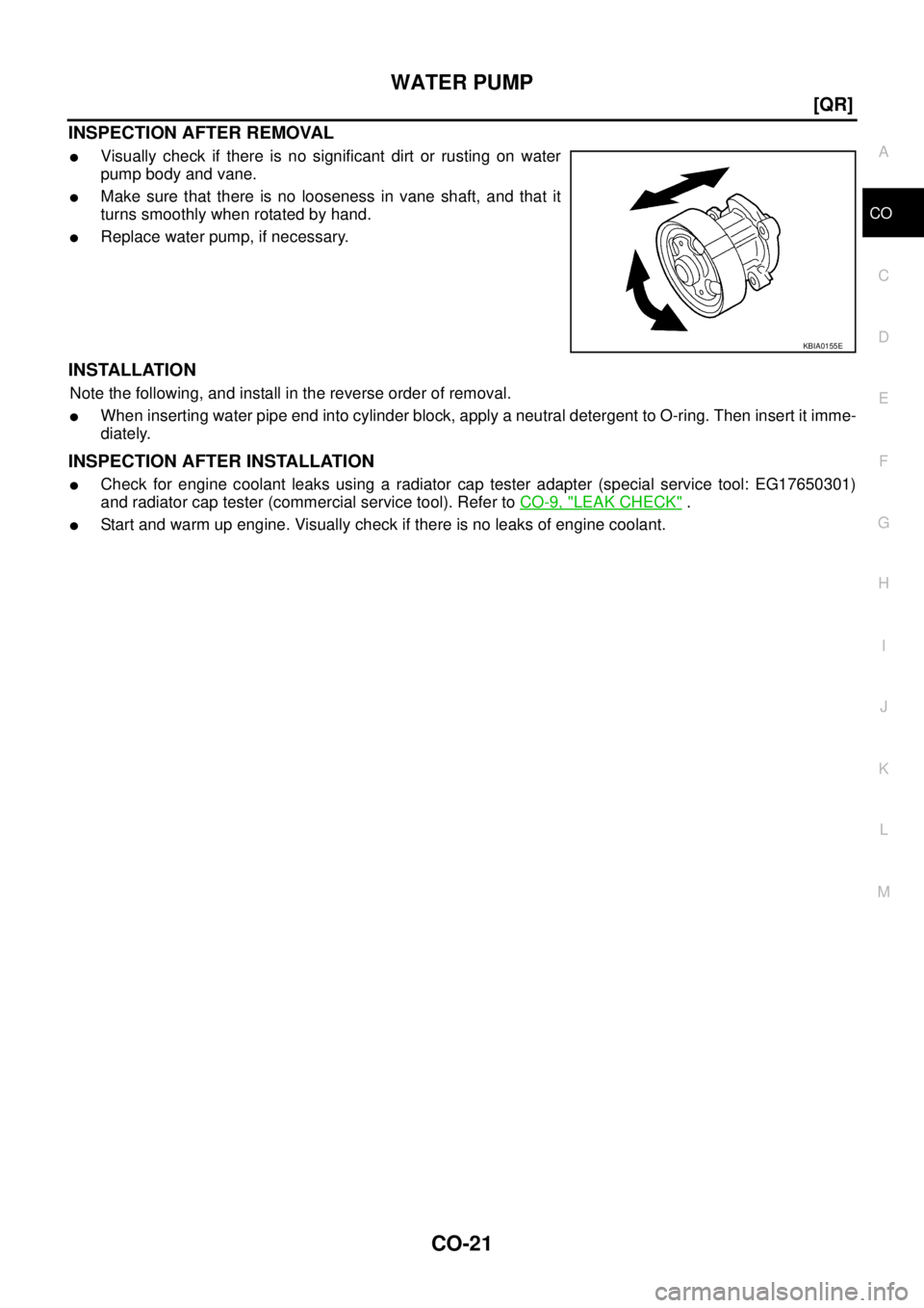
INSPECTION AFTER REMOVAL
�Visually check if there is no significant dirt or rusting on water
pump body and vane.
�Make sure that there is no looseness in vane shaft, and that it
turns smoothly when rotated by hand.
�Replace water pump, if necessary.
INSTALLATION
Note the following, and install in the reverse order of removal.
�When inserting water pipe end into cylinder block, apply a neutral detergent to O-ring. Then insert it imme-
diately.
INSPECTION AFTER INSTALLATION
�Check for engine coolant leaks using a radiator cap tester adapter (special service tool: EG17650301)
and radiator cap tester (commercial service tool). Refer to CO-9, "
LEAK CHECK" .
�Start and warm up engine. Visually check if there is no leaks of engine coolant.
KBIA0155E
Page 354 of 4179
![NISSAN X-TRAIL 2003 Service Repair Manual CO-22
[QR]
THERMOSTAT AND WATER CONTROL VALVE
THERMOSTAT AND WATER CONTROL VALVEPFP:21200
Removal and InstallationEBS00KOO
REMOVAL
1. Drain engine coolant. Refer to CO-9, "Changing Engine Coolant" .](/manual-img/5/57404/w960_57404-353.png "NISSAN X-TRAIL 2003 Service Repair Manual CO-22
[QR]
THERMOSTAT AND WATER CONTROL VALVE
THERMOSTAT AND WATER CONTROL VALVEPFP:21200
Removal and InstallationEBS00KOO
REMOVAL
1. Drain engine coolant. Refer to CO-9, \"Changing Engine Coolant\" .")
CO-22
[QR]
THERMOSTAT AND WATER CONTROL VALVE
THERMOSTAT AND WATER CONTROL VALVEPFP:21200
Removal and InstallationEBS00KOO
REMOVAL
1. Drain engine coolant. Refer to CO-9, "Changing Engine Coolant" .
CAUTION:
�Perform this step when engine is cold.
�Do not spill engine coolant on drive belt.
2. Disconnect radiator hose (lower) at water inlet side. Refer to CO-12, "
RADIATOR" .
3. Remove water inlet and thermostat.
4. Remove water control valve with the following procedure:
a. Disconnect radiator hose (upper) at water control valve housing (water outlet) side.
b. Disconnect harness connector from engine coolant temperature sensor.
c. Remove heater pipe and heater hose.
d. Remove water control valve housing (water outlet) and water control valve.
1. Thermostat 2. O-ring 3. Water inlet
4. Water control valve 5. O-ring 6. Gasket
7. Water control valve housing (water outlet) 8. Washer 9. Engine coolant temperature sensor
10. Heater hose 11. O-ring 12. Heater pipe
13. Heater hose
PBIC2254E
Page 355 of 4179
![NISSAN X-TRAIL 2003 Service Repair Manual THERMOSTAT AND WATER CONTROL VALVE
CO-23
[QR]
C
D
E
F
G
H
I
J
K
L
MA
CO
INSPECTION AFTER REMOVAL
�Place a string so that it is caught in the valves of thermostat and
water control valve. Immerse ful](/manual-img/5/57404/w960_57404-354.png "NISSAN X-TRAIL 2003 Service Repair Manual THERMOSTAT AND WATER CONTROL VALVE
CO-23
[QR]
C
D
E
F
G
H
I
J
K
L
MA
CO
INSPECTION AFTER REMOVAL
�Place a string so that it is caught in the valves of thermostat and
water control valve. Immerse ful")
THERMOSTAT AND WATER CONTROL VALVE
CO-23
[QR]
C
D
E
F
G
H
I
J
K
L
MA
CO
INSPECTION AFTER REMOVAL
�Place a string so that it is caught in the valves of thermostat and
water control valve. Immerse fully in a container filled with water.
Heat while stirring. (The example in the figure shows thermo-
stat.)
�The valve opening temperature is the temperature at which the
valve opens and falls from the thread.
�Continue heating. Check the full open valve lift amount.
NOTE:
The full open valve lift amount standard temperature for water
control valve is the reference value.
�After checking the full open valve lift amount, lower the water
temperature and check the valve closing temperature.
Standard:
�If out of the standard, replace either or both thermostat and water control valve.
INSTALLATION
Note the following, and install in the reverse order of removal.
Thermostat and Water Control Valve
�Install thermostat with making rubber ring groove fit to thermo-
stat flange with the whole circumference. (The example in the
figure shows thermostat.)
NOTE:
Same procedure is applied for installation of water control valve.
�Install thermostat with jiggle valve facing upwards. (The position
deviation may be within the range of 20 degrees as shown in the
figure.)
�Install water control valve with the arrow facing up and the frame
center part facing upwards. (The position deviation may be
within the range of 20 degrees as shown in the figure.)
Heater Pipe Installation
Apply a neutral detergent to O-ring, then quickly insert the insertion part of heater pipe into cylinder block.
INSPECTION AFTER INSTALLATION
�Check for leaks of engine coolant using a radiator cap tester adapter (special service tool: EG17650301)
and a radiator cap tester (commercial service tool). Refer to CO-9, "
LEAK CHECK" .
�Start and warm up engine. Visually check if there is no leaks of engine coolant and A/T fluid (A/T models).
SLC252B
Items Thermostat Water control valve
Valve opening temperature 80.5 - 83.5°C (177 - 182°F) 93.5 - 96.5°C (200 - 206°F)
Full open valve liftMore than 8 mm/ 95°C
(0.315 in/ 203°F)More than 8 mm/ 108°C
(0.315 in/ 226°F)
Valve closing temperature More than 77°C (171°F) More than 90°C (194°F)
PBIC0157E
PBIC0158E
Page 356 of 4179
![NISSAN X-TRAIL 2003 Service Repair Manual CO-24
[QR]
SERVICE DATA AND SPECIFICATIONS (SDS)
SERVICE DATA AND SPECIFICATIONS (SDS)PFP:00030
Standard and LimitEBS00KOP
CAPACITY
Unit: (lmp qt)
THERMOSTAT
WATER CONTROL VALVE
RADIATOR
Unit: kPa](/manual-img/5/57404/w960_57404-355.png "NISSAN X-TRAIL 2003 Service Repair Manual CO-24
[QR]
SERVICE DATA AND SPECIFICATIONS (SDS)
SERVICE DATA AND SPECIFICATIONS (SDS)PFP:00030
Standard and LimitEBS00KOP
CAPACITY
Unit: (lmp qt)
THERMOSTAT
WATER CONTROL VALVE
RADIATOR
Unit: kPa")
CO-24
[QR]
SERVICE DATA AND SPECIFICATIONS (SDS)
SERVICE DATA AND SPECIFICATIONS (SDS)PFP:00030
Standard and LimitEBS00KOP
CAPACITY
Unit: (lmp qt)
THERMOSTAT
WATER CONTROL VALVE
RADIATOR
Unit: kPa (bar, kg/cm2 , psi)
Tightening TorqueEBS00KOQ
Unit: N·m (kg-m, ft-lb)
Unit: N·m (kg-m, in-lb)*
Engine coolant capacity (With reservoir tank at “MAX” level) Approx. 7.1 (6-1/4)
Reservoir tank0.6 (1/2)
Valve opening temperature 80.5 - 83.5°C (177 - 182°F)
Valve liftMore than 8 mm/ 95°C (0.315 in/ 203°F)
Valve closing temperature More than 77°C (171°F)
Valve opening temperature 93.5 - 96.5°C (200 - 206°F)
Valve lift More than 8 mm/ 108°C (0.315 in/ 226°F)
Valve closing temperature More than 90°C (194°F)
Cap relief pressureStandard 78 - 98 (0.78 - 0.98, 0.8 - 1.0, 11- 14)
Limit 59 (0.59, 0.6, 9)
Leakage test pressure 157 (1.57, 1.6, 23)
Radiator mounting bracket 4.2 (0.43, 37)*
Radiator cooling fan assembly 4.2 (0.43, 37)*
Cooling fan3.43 (0.35, 30)*
Fan motor4.41 (0.45, 39)*
Water pump24.5 (2.5, 18)
Water pump housing28.0 (2.9, 21)
Water pipe28.0 (2.9, 21)
Water inlet28.0 (2.9, 21)
Water control valve housing (water outlet) 28.0 (2.9, 21)
Hater pipe28.0 (2.9, 21)
Engine coolant temperature sensor 24.5 (2.5, 18)