Page 2435 of 4179
A/T SHIFT LOCK SYSTEM
AT-399
[ALL]
D
E
F
G
H
I
J
K
L
MA
B
AT
Wiring Diagram — SHIFTECS00407
TCWA0241E
Page 2436 of 4179
![NISSAN X-TRAIL 2003 Service Repair Manual AT-400
[ALL]
A/T SHIFT LOCK SYSTEM
Diagnostic ProcedureECS00408
SYMPTOM 1:
�Selector lever cannot be moved from “P” position with key in ON position and brake pedal
applied.
�Selector lever can](/manual-img/5/57404/w960_57404-2435.png "NISSAN X-TRAIL 2003 Service Repair Manual AT-400
[ALL]
A/T SHIFT LOCK SYSTEM
Diagnostic ProcedureECS00408
SYMPTOM 1:
�Selector lever cannot be moved from “P” position with key in ON position and brake pedal
applied.
�Selector lever can")
AT-400
[ALL]
A/T SHIFT LOCK SYSTEM
Diagnostic ProcedureECS00408
SYMPTOM 1:
�Selector lever cannot be moved from “P” position with key in ON position and brake pedal
applied.
�Selector lever can be moved from “P” position with key in ON position and brake pedal released.
�Selector lever can be moved from “P” position when key is removed from key cylinder.
SYMPTOM 2:
�Ignition key cannot be removed when selector lever is set to “P” position.
�Ignition key can be removed when selector lever is set to any position except “P”.
1. CHECK KEY INTERLOCK CABLE
Check key interlock cable for damage.
OK or NG
OK >> GO TO 2.
NG >> Repair key interlock cable. Refer to AT- 4 0 2 , "
KEY INTERLOCK CABLE" .
2. CHECK SELECTOR LEVER POSITION
Check selector lever position for damage.
OK or NG
OK >> GO TO 3.
NG >> Check selector lever. Refer to AT- 4 0 9 , "
Park/Neutral Position (PNP) Switch Adjustment" .
3. CHECK SHIFT LOCK SOLENOID AND PARK POSITION SWITCH
1. Turn ignition switch to ON. (Do not start engine.)
2. Selector lever is set in P position.
3. Check operation sound.
OK or NG
OK >>INSPECTION END
NG >> GO TO 4.
4. CHECK POWER SOURCE
1. Turn ignition switch to ON. (Do not start engine.)
2. Check voltage between A/T device harness connector M58 ter-
minal 5 (P) and ground.
OK or NG
OK >> GO TO 7.
NG >> GO TO 5.
Condition Brake pedal Operation sound
When ignition switch is turned to
“ON” position and selector lever
is set in “P” position.Depressed Yes
Released No
Voltage:
Brake pedal depressed:
Battery voltage
Brake pedal released:
0V
SCIA5337E
Page 2437 of 4179
![NISSAN X-TRAIL 2003 Service Repair Manual A/T SHIFT LOCK SYSTEM
AT-401
[ALL]
D
E
F
G
H
I
J
K
L
MA
B
AT
5. CHECK STOP LAMP SWITCH
1. Turn ignition switch to OFF.
2. Disconnect stop lamp switch harness connector.
3. Check continuity between s](/manual-img/5/57404/w960_57404-2436.png "NISSAN X-TRAIL 2003 Service Repair Manual A/T SHIFT LOCK SYSTEM
AT-401
[ALL]
D
E
F
G
H
I
J
K
L
MA
B
AT
5. CHECK STOP LAMP SWITCH
1. Turn ignition switch to OFF.
2. Disconnect stop lamp switch harness connector.
3. Check continuity between s")
A/T SHIFT LOCK SYSTEM
AT-401
[ALL]
D
E
F
G
H
I
J
K
L
MA
B
AT
5. CHECK STOP LAMP SWITCH
1. Turn ignition switch to OFF.
2. Disconnect stop lamp switch harness connector.
3. Check continuity between stop lamp switch harness connector M12 terminals 3 (G) and 4 (P).
Check stop lamp switch after adjusting brake pedal — refer to BR-6, "
BRAKE PEDAL" .
OK or NG
OK >> GO TO 6.
NG >> Repair or replace damaged parts.
6. DETECT MALFUNCTIONING ITEM
Check the following items. If any items are damaged, repair or replace damaged parts.
1. Harness for short or open between battery and stop lamp switch harness connector 3 (G)
2. Harness for short or open between stop lamp switch harness connector 4 (P) and A/T device harness
connector 5 (P)
3. 15A fuse [No.22, located in the fuse block (J/B)]
4. Ignition switch (Refer to PG-2, "
POWER SUPPLY ROUTING" .)
OK or NG
OK >>INSPECTION END
NG >> Repair or replace damaged parts.
7. CHECK GROUND CIRCUIT
1. Turn ignition switch to OFF.
2. Disconnect A/T device harness connector.
3. Check continuity between A/T device harness connector M58
terminal 6 (B) and ground.
4. Connect A/T device harness connector.
OK or NG
OK >> Replace shift lock solenoid or park position switch.
NG >> Repair open circuit or short to ground or short to power
in harness or connectors.
SCIA1796E
Continuity should exist.
SCIA4284E
Page 2438 of 4179
AT-402
[ALL]
KEY INTERLOCK CABLE
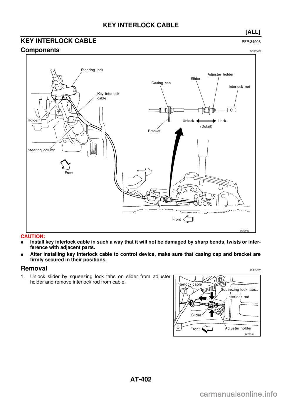
KEY INTERLOCK CABLEPFP:34908
ComponentsECS00409
CAUTION:
�Install key interlock cable in such a way that it will not be damaged by sharp bends, twists or inter-
ference with adjacent parts.
�After installing key interlock cable to control device, make sure that casing cap and bracket are
firmly secured in their positions.
RemovalECS0040A
1. Unlock slider by squeezing lock tabs on slider from adjuster
holder and remove interlock rod from cable.
SAT996J
SAT853J
Page 2439 of 4179
KEY INTERLOCK CABLE
AT-403
[ALL]
D
E
F
G
H
I
J
K
L
MA
B
AT
2. Remove lock plate from steering lock assembly and remove key
interlock cable.
InstallationECS0040B
1. Turn ignition key to lock position.
2. Set A/T selector lever to P position.
3. Set key interlock cable to steering lock assembly and install lock
plate.
4. Clamp cable to steering column and fix to control cable with
band.
5. Insert interlock rod into adjuster holder.
6. Install casing cap to bracket.
7. Move slider in order to fix adjuster holder to interlock rod.
SAT854J
SAT854J
SAT804E
SAT805E
Page 2445 of 4179
![NISSAN X-TRAIL 2003 Service Repair Manual ON-VEHICLE SERVICE
AT-409
[ALL]
D
E
F
G
H
I
J
K
L
MA
B
AT
�After installation is completed, adjust and check A/T position. Refer to AT- 4 0 9 , "Control Cable Adjustment"
, AT- 4 0 9 , "Park/Neutr](/manual-img/5/57404/w960_57404-2444.png "NISSAN X-TRAIL 2003 Service Repair Manual ON-VEHICLE SERVICE
AT-409
[ALL]
D
E
F
G
H
I
J
K
L
MA
B
AT
�After installation is completed, adjust and check A/T position. Refer to AT- 4 0 9 , \"Control Cable Adjustment\"
, AT- 4 0 9 , \"Park/Neutr")
ON-VEHICLE SERVICE
AT-409
[ALL]
D
E
F
G
H
I
J
K
L
MA
B
AT
�After installation is completed, adjust and check A/T position. Refer to AT- 4 0 9 , "Control Cable Adjustment"
, AT- 4 0 9 , "Park/Neutral Position (PNP) Switch Adjustment" .
�After installation is completed, check continuity of PNP switch. Refer to AT- 1 0 0 , "DTC P0705 PARK/NEU-
TRAL POSITION (PNP) SWITCH" .
CONTROL CABLE ADJUSTMENT
Move selector lever from the P position to the 1 position. You should
be able to feel the detents in each position. If the detents cannot be
felt or if the pointer indicating the position is improperly aligned, the
control cable needs adjustment.
1. Place selector lever in P position.
2. Loosen control cable lock nut and place manual shaft in P posi-
tion.
3. Pull control cable, by specified force, in the direction of the arrow
shown in the illustration.
4. Return control cable in the opposite direction of the arrow for 1.0
mm (0.039 in).
5. Tighten control cable lock nut.
6. Move selector lever from P to 1 position again. Make sure that
selector lever moves smoothly.
7. Apply grease to contacting areas of selector lever and control
cable. Install any part removed.
PARK/NEUTRAL POSITION (PNP) SWITCH ADJUSTMENT
1. Set select lever and manual shaft in N position.
2. Remove control cable end from manual shaft.
3. Loosen PNP switch fixing bolts.
4. Use a 3 mm (0.12 in) pin for this adjustment.
a. Insert the pin straight into the manual shaft adjustment hole.
b. Rotate PNP switch until the pin can also be inserted straight into
hole in PNP switch.
5. Tighten PNP switch fixing bolts.
6. Remove pin from adjustment hole after adjusting PNP switch.
7. Reinstall any part removed.
8. Adjust control cable. Refer to AT- 4 0 9 , "
Control Cable Adjust-
ment" .
9. Check continuity of PNP switch. Refer to AT- 2 3 7
(EUR-OBD) or AT- 3 2 4 (Except EUR-OBD). Specified force: 6.9N (0.7 kg, 1.5 lb)
AAT980
SCIA3156E
SCIA3154E
Page 2450 of 4179
AT-414
[ALL]
REMOVAL AND INSTALLATION
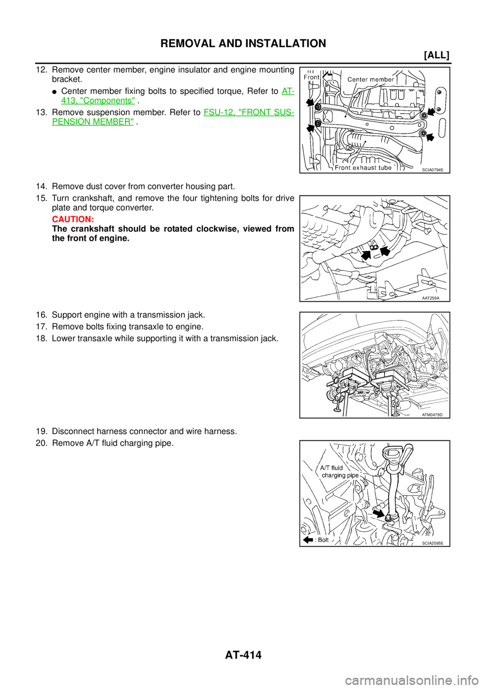
12. Remove center member, engine insulator and engine mounting
bracket.
�Center member fixing bolts to specified torque, Refer to AT-
413, "Components" .
13. Remove suspension member. Refer to FSU-12, "
FRONT SUS-
PENSION MEMBER" .
14. Remove dust cover from converter housing part.
15. Turn crankshaft, and remove the four tightening bolts for drive
plate and torque converter.
CAUTION:
The crankshaft should be rotated clockwise, viewed from
the front of engine.
16. Support engine with a transmission jack.
17. Remove bolts fixing transaxle to engine.
18. Lower transaxle while supporting it with a transmission jack.
19. Disconnect harness connector and wire harness.
20. Remove A/T fluid charging pipe.
SCIA0794E
AAT259A
ATM0479D
SCIA2595E
Page 2451 of 4179
![NISSAN X-TRAIL 2003 Service Repair Manual REMOVAL AND INSTALLATION
AT-415
[ALL]
D
E
F
G
H
I
J
K
L
MA
B
AT
21. Remove fluid cooler tube.
INSPECTION
Installation and inspection of torque converter
� After inserting a torque converter to a tra](/manual-img/5/57404/w960_57404-2450.png "NISSAN X-TRAIL 2003 Service Repair Manual REMOVAL AND INSTALLATION
AT-415
[ALL]
D
E
F
G
H
I
J
K
L
MA
B
AT
21. Remove fluid cooler tube.
INSPECTION
Installation and inspection of torque converter
� After inserting a torque converter to a tra")
REMOVAL AND INSTALLATION
AT-415
[ALL]
D
E
F
G
H
I
J
K
L
MA
B
AT
21. Remove fluid cooler tube.
INSPECTION
Installation and inspection of torque converter
� After inserting a torque converter to a transaxle, be sure to
check distance “A” to ensure it is within the reference value limit.
InstallationECS004ND
Install the removed parts in the reverse order of the removal, while paying attention to the following work.
�When installing transaxle to the engine, attach the fixing bolts in
accordance with the following standard.
�Align the positions of tightening bolts for drive plate with those of
the torque converter, and temporarily tighten the bolts. Then,
tighten the bolts to the specified torque. Refer to AT- 4 1 6 , "
Com-
ponents" .
CAUTION:
�When turning crankshaft, turn it clockwise as viewed from
the front of the engine.
�When tightening the tightening bolts for the torque con-
verter after fixing the crankshaft pulley bolts, be sure to
confirm the tightening torque of the crankshaft pulley
mounting bolts.
� After converter is installed to drive plate, rotate crankshaft
several turns and check to be sure that transaxle rotates freely without binding.
�After completing installation, check for fluid leakage, fluid level, and the positions of A/T. Refer to AT- 1 6 ,
"Checking A/T Fluid" , AT- 4 0 9 , "Control Cable Adjustment" .
SCIA2596E
Distance “A”
QR20DE models: 19.0 mm (0.75 in) or more
QR25DE models: 14.0 mm (0.55 in) or more
SAT573D
Bolt No.Tightening torque
N·m (kg-m, ft-lb)Bolt length “ L ”
mm (in)
1
75 (7.7, 55)49 (1.93)
2 45 (1.77)
3
43 (4.4, 32)40 (1.57)
4 30 (1.18)
5
36 (3.7, 27)40 (1.57)
6 45 (1.97)
SCIA0795E
SCIA3138E
![NISSAN X-TRAIL 2003 Service Repair Manual A/T SHIFT LOCK SYSTEM
AT-399
[ALL]
D
E
F
G
H
I
J
K
L
MA
B
AT
Wiring Diagram — SHIFTECS00407
TCWA0241E](/manual-img/5/57404/w960_57404-2434.png "NISSAN X-TRAIL 2003 Service Repair Manual A/T SHIFT LOCK SYSTEM
AT-399
[ALL]
D
E
F
G
H
I
J
K
L
MA
B
AT
Wiring Diagram — SHIFTECS00407
TCWA0241E")
![NISSAN X-TRAIL 2003 Service Repair Manual KEY INTERLOCK CABLE
AT-403
[ALL]
D
E
F
G
H
I
J
K
L
MA
B
AT
2. Remove lock plate from steering lock assembly and remove key
interlock cable.
InstallationECS0040B
1. Turn ignition key to lock position](/manual-img/5/57404/w960_57404-2438.png "NISSAN X-TRAIL 2003 Service Repair Manual KEY INTERLOCK CABLE
AT-403
[ALL]
D
E
F
G
H
I
J
K
L
MA
B
AT
2. Remove lock plate from steering lock assembly and remove key
interlock cable.
InstallationECS0040B
1. Turn ignition key to lock position")