Page 2533 of 4179
REPAIR FOR COMPONENT PARTS
AT-497
[ALL]
D
E
F
G
H
I
J
K
L
MA
B
AT
Band Servo Piston AssemblyECS00ECA
COMPONENTS
DISASSEMBLY
1. Remove O/D servo piston retainer fitting bolts.
2. Apply compressed air to oil hole in transaxle case to remove O/
D servo piston retainer and band servo piston assembly.
CAUTION:
Hold band servo piston assembly with a rag or nylon waste.
3. Remove 2nd servo return spring from transaxle case.
1. Lock nut 2. Anchor end pin 3. Brake band
4. Strut 5. O-ring 6. Servo piston retainer
7. D-ring 8. O/D servo piston 9. O-rings
10. O/D servo piston retainer 11. E-ring 12. Spring retainer
13. O/D servo return spring 14. D-ring 15. Band servo piston
16. Band servo thrust washer 17. Band servo piston stem 18. 2nd servo return spring
SCIA4908E
AAT879
SCIA4447E
Page 2534 of 4179
AT-498
[ALL]
REPAIR FOR COMPONENT PARTS
4. Apply compressed air to oil hole in O/D servo piston retainer to
remove O/D servo piston from O/D servo piston retainer.
CAUTION:
Hold O/D servo piston while applying compressed air.
5. Remove D-ring from O/D servo piston.
6. Remove O-rings from O/D servo piston retainer.
7. Remove band servo piston assembly from servo piston retainer
by pushing it forward.
8. Place band servo piston stem end on a wooden block. While
pushing spring retainer down, remove E-ring.
SCIA5645E
SCIA3689E
SCIA5646E
SAT293D
SAT294D
Page 2536 of 4179
AT-500
[ALL]
REPAIR FOR COMPONENT PARTS
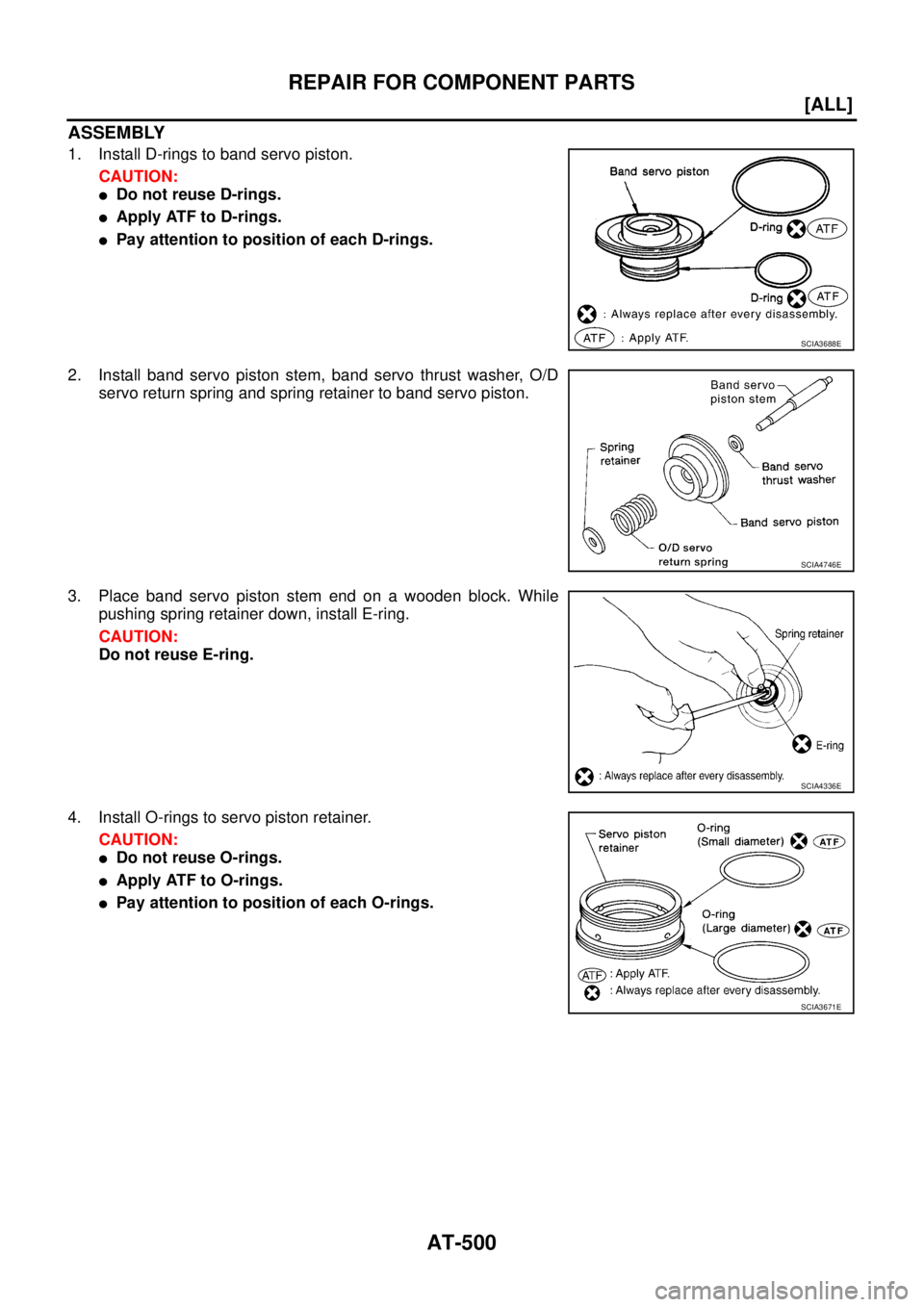
ASSEMBLY
1. Install D-rings to band servo piston.
CAUTION:
�Do not reuse D-rings.
�Apply ATF to D-rings.
�Pay attention to position of each D-rings.
2. Install band servo piston stem, band servo thrust washer, O/D
servo return spring and spring retainer to band servo piston.
3. Place band servo piston stem end on a wooden block. While
pushing spring retainer down, install E-ring.
CAUTION:
Do not reuse E-ring.
4. Install O-rings to servo piston retainer.
CAUTION:
�Do not reuse O-rings.
�Apply ATF to O-rings.
�Pay attention to position of each O-rings.
SCIA3688E
SCIA4746E
SCIA4336E
SCIA3671E
Page 2539 of 4179
REPAIR FOR COMPONENT PARTS
AT-503
[ALL]
D
E
F
G
H
I
J
K
L
MA
B
AT
Final DriveECS00ECB
COMPONENTS
DISASSEMBLY
1. Remove final gear.
2. Press out differential side bearings.
CAUTION:
Be careful not to mix up the right and left bearings.
1. Pinion mate gear 2. Pinion mate gear thrust washer 3. Pinion mate shaft
4. Lock pin 5. Side gear 6. Side gear thrust washer
7. Differential side bearing 8. Differential case 9. Final gear
10. Differential side bearing 11. Differential side bearing adjusting
shim
SCIA3346E
SMT505B
SMT744AA
Page 2540 of 4179
AT-504
[ALL]
REPAIR FOR COMPONENT PARTS
3. Remove differential side bearing outer race, and side bearing
adjusting shim from transaxle case.
4. Drive out lock pin.
5. Draw out pinion mate shaft.
6. Remove pinion mate gears, pinion mate gear thrust washers,
side gears and side gear thrust washers.
INSPECTION
Gear, Washer, Shaft and Case
�Check mating surfaces of differential case, side gears, pinion
mate gears and pinion mate shaft.
�Check washers for wear.
SAT010FA
SAT904DA
SAT316D
SAT544F
Page 2542 of 4179
AT-506
[ALL]
REPAIR FOR COMPONENT PARTS
b. Move side gear up and down to measure dial indicator deflec-
tion. Always measure indicator deflection on both side gears.
c. If not within specification, adjust the clearance by changing the
thickness of differential side gear thrust washers. Refer to AT-
535, "Final Drive" .
4. Install lock pin.
CAUTION:
�Do not reuse lock pin.
�Make sure that lock pin is flush with case.
5. Press on differential side bearings.
CAUTION:
Apply ATF to differential side bearings.
6. Install differential side bearing outer race and differential side
bearing adjusting shim on transaxle case. Refer to AT- 5 0 8 ,
"Adjustment (1)" .
7. Tighten final gear and tighten fixing bolts to the specified torque
in numerical order shown in the figure after temporarily tighten-
ing them. Refer to AT- 5 0 3 , "
COMPONENTS" . Clearance between side gear and differential case
with washer:
0.1 - 0.2 mm (0.004 - 0.008 in)
SMT611A
SMT699BA
SAT545FA
ATM0432D
Page 2547 of 4179
![NISSAN X-TRAIL 2003 Service Repair Manual ASSEMBLY
AT-511
[ALL]
D
E
F
G
H
I
J
K
L
MA
B
AT
6. Set manual shaft to “P” position to fix idler gear.
7. Tighten idler gear lock nut to the specified torque. Refer to AT-
416, "Components" .
CA](/manual-img/5/57404/w960_57404-2546.png "NISSAN X-TRAIL 2003 Service Repair Manual ASSEMBLY
AT-511
[ALL]
D
E
F
G
H
I
J
K
L
MA
B
AT
6. Set manual shaft to “P” position to fix idler gear.
7. Tighten idler gear lock nut to the specified torque. Refer to AT-
416, \"Components\" .
CA")
ASSEMBLY
AT-511
[ALL]
D
E
F
G
H
I
J
K
L
MA
B
AT
6. Set manual shaft to “P” position to fix idler gear.
7. Tighten idler gear lock nut to the specified torque. Refer to AT-
416, "Components" .
CAUTION:
Lock idler gear with parking pawl when tightening lock nut.
8. Measure turning torque of reduction pinion gear.
�When measuring turning torque, turn reduction pinion
gear in both directions several times to seat bearing roll-
ers correctly.
�If turning torque is out of specification, decrease or
increase the thickness of reduction pinion gear bearing
adjusting shim.
9. After properly adjusting turning torque, clinch idler gear lock nut
as shown.
CAUTION:
Do not reuse idler gear lock nut.
OUTPUT SHAFT END PLAY
�Measure the clearance between side cover and the end of the
output shaft bearing.
�Select proper thickness of output shaft adjusting shim so that
clearance is within specifications.
SAT189F
Turning torque of reduction pinion gear:
0.05 - 0.39 N-m (0.5 - 4.0 kg-cm, 0.43 - 3.47 in-lb)
SAT190FB
SCIA4451E
SAT341D
Page 2549 of 4179
![NISSAN X-TRAIL 2003 Service Repair Manual ASSEMBLY
AT-513
[ALL]
D
E
F
G
H
I
J
K
L
MA
B
AT
6. Select proper thickness of output shaft adjusting shim so that
output shaft end play (clearance between side cover and output
shaft bearing) is wit](/manual-img/5/57404/w960_57404-2548.png "NISSAN X-TRAIL 2003 Service Repair Manual ASSEMBLY
AT-513
[ALL]
D
E
F
G
H
I
J
K
L
MA
B
AT
6. Select proper thickness of output shaft adjusting shim so that
output shaft end play (clearance between side cover and output
shaft bearing) is wit")
ASSEMBLY
AT-513
[ALL]
D
E
F
G
H
I
J
K
L
MA
B
AT
6. Select proper thickness of output shaft adjusting shim so that
output shaft end play (clearance between side cover and output
shaft bearing) is within specifications. Refer to AT- 5 3 8 , "
OUT-
PUT SHAFT ADJUSTING SHIMS" .
7. Install output shaft adjusting shim on output shaft bearing.
Assembly (2)ECS004MF
1. Apply locking sealant (Locktite #518) to transaxle case as
shown in illustration.
2. Fit the mounting part of output shaft bearing on side cover to
output shaft bearing, and after adjusting knock pin position,
install it with light taps using a soft hammer and things like that.
CAUTION:
When installing, to avoid getting damaged and deformed,
set the mounting part straight to parallel with the mounting
surface.
3. Tighten side cover fixing bolts to specified torque. Refer to AT-
416, "Components" .
CAUTION:
�Do not mix bolts A and B.
�Always replace bolts A as they are self-sealing bolts.Output shaft end play (A − B):
0 - 0.15 mm (0 - 0.0059 in)
SAT440D
SCIA4919E
SAT442D
AAT850
![NISSAN X-TRAIL 2003 Service Repair Manual REPAIR FOR COMPONENT PARTS
AT-497
[ALL]
D
E
F
G
H
I
J
K
L
MA
B
AT
Band Servo Piston AssemblyECS00ECA
COMPONENTS
DISASSEMBLY
1. Remove O/D servo piston retainer fitting bolts.
2. Apply compressed air](/manual-img/5/57404/w960_57404-2532.png "NISSAN X-TRAIL 2003 Service Repair Manual REPAIR FOR COMPONENT PARTS
AT-497
[ALL]
D
E
F
G
H
I
J
K
L
MA
B
AT
Band Servo Piston AssemblyECS00ECA
COMPONENTS
DISASSEMBLY
1. Remove O/D servo piston retainer fitting bolts.
2. Apply compressed air")
![NISSAN X-TRAIL 2003 Service Repair Manual AT-498
[ALL]
REPAIR FOR COMPONENT PARTS
4. Apply compressed air to oil hole in O/D servo piston retainer to
remove O/D servo piston from O/D servo piston retainer.
CAUTION:
Hold O/D servo piston whi](/manual-img/5/57404/w960_57404-2533.png "NISSAN X-TRAIL 2003 Service Repair Manual AT-498
[ALL]
REPAIR FOR COMPONENT PARTS
4. Apply compressed air to oil hole in O/D servo piston retainer to
remove O/D servo piston from O/D servo piston retainer.
CAUTION:
Hold O/D servo piston whi")
![NISSAN X-TRAIL 2003 Service Repair Manual REPAIR FOR COMPONENT PARTS
AT-503
[ALL]
D
E
F
G
H
I
J
K
L
MA
B
AT
Final DriveECS00ECB
COMPONENTS
DISASSEMBLY
1. Remove final gear.
2. Press out differential side bearings.
CAUTION:
Be careful not to](/manual-img/5/57404/w960_57404-2538.png "NISSAN X-TRAIL 2003 Service Repair Manual REPAIR FOR COMPONENT PARTS
AT-503
[ALL]
D
E
F
G
H
I
J
K
L
MA
B
AT
Final DriveECS00ECB
COMPONENTS
DISASSEMBLY
1. Remove final gear.
2. Press out differential side bearings.
CAUTION:
Be careful not to")
![NISSAN X-TRAIL 2003 Service Repair Manual AT-504
[ALL]
REPAIR FOR COMPONENT PARTS
3. Remove differential side bearing outer race, and side bearing
adjusting shim from transaxle case.
4. Drive out lock pin.
5. Draw out pinion mate shaft.
6.](/manual-img/5/57404/w960_57404-2539.png "NISSAN X-TRAIL 2003 Service Repair Manual AT-504
[ALL]
REPAIR FOR COMPONENT PARTS
3. Remove differential side bearing outer race, and side bearing
adjusting shim from transaxle case.
4. Drive out lock pin.
5. Draw out pinion mate shaft.
6.")
![NISSAN X-TRAIL 2003 Service Repair Manual AT-506
[ALL]
REPAIR FOR COMPONENT PARTS
b. Move side gear up and down to measure dial indicator deflec-
tion. Always measure indicator deflection on both side gears.
c. If not within specification,](/manual-img/5/57404/w960_57404-2541.png "NISSAN X-TRAIL 2003 Service Repair Manual AT-506
[ALL]
REPAIR FOR COMPONENT PARTS
b. Move side gear up and down to measure dial indicator deflec-
tion. Always measure indicator deflection on both side gears.
c. If not within specification,")