Page 2638 of 4179
TF-62
TRANSFER ASSEMBLY
DISASSEMBLY
Pinion Sleeve Assembly
1. Remove pinion sleeve mounting bolts.
2. Using a plastic hammer, tap companion flange to remove pinion
sleeve assembly.
3. Remove the pinion sleeve shim.
4. Remove the pinion lock nut.
5. Using a drift, remove drive pinion assembly from pinion sleeve
with a press.
6. Remove companion flange.
7. Remove the O-ring from pinion sleeve.
8. Using a flat-bladed screwdriver, remove the pinion sleeve oil
seal.
CAUTION:
Be careful not to damage the pinion sleeve.
9. Remove the pinion rear bearing inner race.
SDIA1803J
SDIA1861J
Tool number : ST33220000
SDIA1806E
TFB0286D
Page 2646 of 4179

TF-70
TRANSFER ASSEMBLY
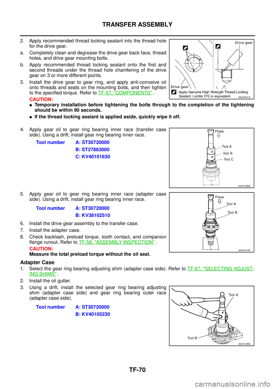
2. Apply recommended thread locking sealant into the thread hole
for the drive gear.
a. Completely clean and degrease the drive gear back face, thread
holes, and drive gear mounting bolts.
b. Apply recommended thread locking sealant onto the first and
second threads under the thread hole chamfering of the drive
gear on 3 or more different points.
3. Install the drive gear to gear ring, and apply anti-corrosive oil
onto threads and seats on the mounting bolts, and then tighten
to the specified torque. Refer to TF-57, "
COMPONENTS" .
CAUTION:
�Temporary installation before tightening the bolts through to the completion of the tightening
should be within 90 seconds.
�If the thread locking sealant is applied aside, quickly wipe it off.
4. Apply gear oil to gear ring bearing inner race (transfer case
side). Using a drift, install gear ring bearing inner race.
5. Apply gear oil to gear ring bearing inner race (adapter case
side). Using a drift, install gear ring bearing inner race.
6. Install the drive gear assembly to the transfer case.
7. Install the adapter case.
8. Check backlash, preload torque, tooth contact, and companion
flange runout. Refer to TF-58, "
ASSEMBLY INSPECTION" .
CAUTION:
Measure the total preload torque without the oil seal.
Adapter Case
1. Select the gear ring bearing adjusting shim (adapter case side). Refer to TF-67, "SELECTING ADJUST-
ING SHIMS" .
2. Install the oil gutter.
3. Using a drift, install the selected gear ring bearing adjusting
shim (adapter case side) and gear ring bearing outer race
(adapter case side).
SDIA0541E
Tool number A: ST30720000
B: ST27863000
C: KV40101630
SDIA1566E
Tool number A: ST30720000
B: KV38102510
SDIA1810E
Tool number A: ST30720000
B: KV40105230
SDIA1535E
Page 2649 of 4179

TRANSFER ASSEMBLY
TF-73
C
E
F
G
H
I
J
K
L
MA
B
TF
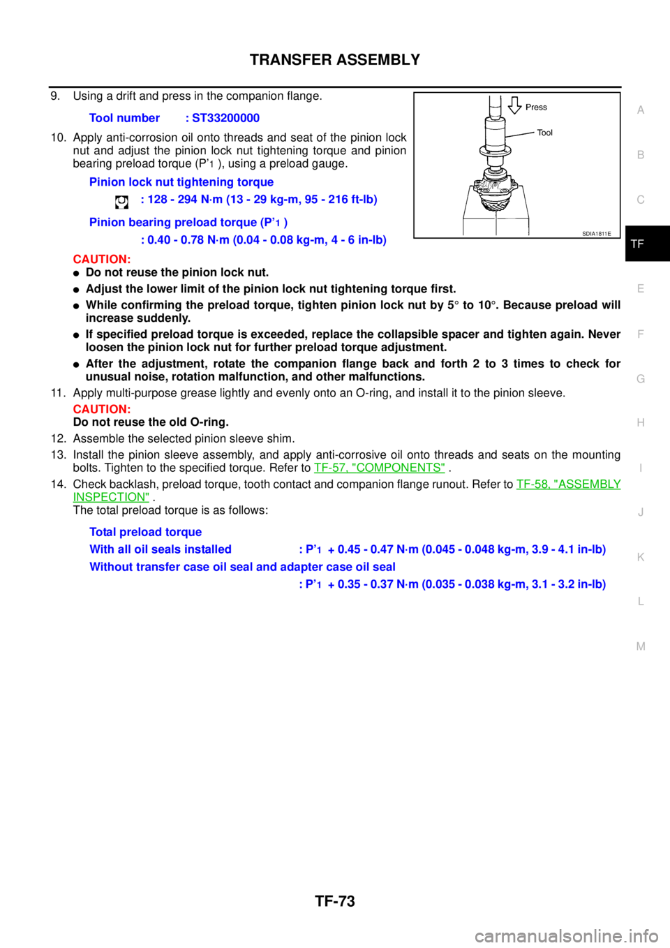
9. Using a drift and press in the companion flange.
10. Apply anti-corrosion oil onto threads and seat of the pinion lock
nut and adjust the pinion lock nut tightening torque and pinion
bearing preload torque (P’
1 ), using a preload gauge.
CAUTION:
�Do not reuse the pinion lock nut.
�Adjust the lower limit of the pinion lock nut tightening torque first.
�While confirming the preload torque, tighten pinion lock nut by 5° to 10°. Because preload will
increase suddenly.
�If specified preload torque is exceeded, replace the collapsible spacer and tighten again. Never
loosen the pinion lock nut for further preload torque adjustment.
�After the adjustment, rotate the companion flange back and forth 2 to 3 times to check for
unusual noise, rotation malfunction, and other malfunctions.
11. Apply multi-purpose grease lightly and evenly onto an O-ring, and install it to the pinion sleeve.
CAUTION:
Do not reuse the old O-ring.
12. Assemble the selected pinion sleeve shim.
13. Install the pinion sleeve assembly, and apply anti-corrosive oil onto threads and seats on the mounting
bolts. Tighten to the specified torque. Refer to TF-57, "
COMPONENTS" .
14. Check backlash, preload torque, tooth contact and companion flange runout. Refer to TF-58, "
ASSEMBLY
INSPECTION" .
The total preload torque is as follows:Tool number : ST33200000
Pinion lock nut tightening torque
: 128 - 294 N·m (13 - 29 kg-m, 95 - 216 ft-lb)
Pinion bearing preload torque (P’
1 )
: 0.40 - 0.78 N·m (0.04 - 0.08 kg-m, 4 - 6 in-lb)
Total preload torque
With all oil seals installed : P’
1 + 0.45 - 0.47 N·m (0.045 - 0.048 kg-m, 3.9 - 4.1 in-lb)
Without transfer case oil seal and adapter case oil seal
: P’
1 + 0.35 - 0.37 N·m (0.035 - 0.038 kg-m, 3.1 - 3.2 in-lb)
SDIA1811E
Page 2663 of 4179

PREPARATION
RFD-3
C
E
F
G
H
I
J
K
L
MA
B
RFD
PREPARATIONPFP:00002
Special Service ToolsEDS001YZ
Tool number
Tool nameDescription
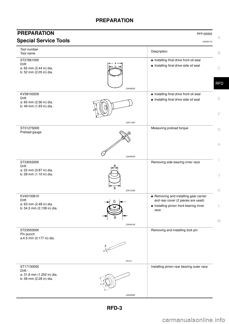
ST27861000
Drift
a: 62 mm (2.44 in) dia.
b: 52 mm (2.05 in) dia.
�Installing final drive front oil seal
�Installing final drive side oil seal
KV38100200
Drift
a: 65 mm (2.56 in) dia.
b: 49 mm (1.93 in) dia.
�Installing final drive front oil seal
�Installing final drive side oil seal
ST3127S000
Preload gaugeMeasuring preload torque
ST33052000
Drift
a: 22 mm (0.87 in) dia.
b: 28 mm (1.10 in) dia.Removing side bearing inner race
KV40100610
Drift
a: 63 mm (2.48 in) dia.
b: 54.3 mm (2.138 in) dia.
�Removing and installing gear carrier
and rear cover (2 pieces are used)
�Installing pinion front bearing inner
race
ST23550000
Pin punch
a:4.5 mm (0.177 in) dia.Removing and installing lock pin
ST17130000
Drift
a: 31.8 mm (1.252 in) dia.
b: 58 mm (2.28 in) dia.Installing pinion rear bearing outer race
ZZA0832D
ZZA1143D
ZZA0503D
ZZA1023D
ZZA0810D
NT410
ZZA0836D
Page 2665 of 4179
PREPARATION
RFD-5
C
E
F
G
H
I
J
K
L
MA
B
RFD
Commercial Service ToolsEDS0027I
KV38108400
Pinion nut wrenchMeasuring preload
ST22360002
(J-25679-01)
Drift
a: 29 mm (1.14 in) dia.
b: 23 mm (0.91 in) dia.
c: 150 mm (5.91 in)Installing coupling front bearing Tool number
Tool nameDescription
ZZA1206D
ZZA0546D
Tool nameDescription
Flange wrench Removing and installing companion flange
lock nut
Power toolLoosening nuts and bolts
NT771
PBIC0190E
Page 2669 of 4179
FRONT OIL SEAL
RFD-9
C
E
F
G
H
I
J
K
L
MA
B
RFD
FRONT OIL SEALPFP:38189
Removal and InstallationEDS001Z2
REMOVAL
1. Remove propeller shaft. Refer to PR-4, "Removal and Installation" .
2. Put matching mark on the thread edge of electric controlled cou-
pling. The matching mark should be in line with the matching
mark on companion flange.
CAUTION:
For matching mark, use paint. Do not damage electric con-
trolled coupling.
3. Remove companion flange lock nut, using a flange wrench.
Then remove companion flange.
4. Remove front oil seal from coupling cover, using a flat-bladed
screwdriver.
CAUTION:
Be careful not to damage coupling cover.
INSTALLATION
1. Apply multi-purpose grease to front oil seal lips.
2. Install front oil seal until it becomes flush with the case end,
using the drifts.
CAUTION:
�Do not reuse oil seal.
�When installing, do not incline oil seal.
PDIA0455E
PDIA0456E
PDIA0457E
Tool number A: KV38100200
B: ST27861000
PDIA0038E
Page 2670 of 4179
RFD-10
FRONT OIL SEAL
3. Align the matching mark of electric controlled coupling with the
matching mark of companion flange, then install the companion
flange.
4. Install companion flange lock nut with a flange wrench, tighten
the to the specified torque. Refer to RFD-16, "
Components" .
CAUTION:
Do not reuse companion flange lock nut.
5. Install propeller shaft. Refer to PR-4, "
Removal and Installation"
.
PDIA0455E
Page 2672 of 4179
RFD-12
ELECTRIC CONTROLLED COUPLING
ELECTRIC CONTROLLED COUPLINGPFP:38760
Removal and InstallationEDS0027J
REMOVAL
1. Remove propeller shaft. Refer to PR-4, "Removal and Installation" .
2. Put matching mark on the thread edge of electric controlled cou-
pling. The matching mark should be in line with the matching
mark on the companion flange.
CAUTION:
For matching mark, use paint. Do not damage electric con-
trolled coupling.
NOTE:
When replacing electric controlled coupling, matching mark is
not necessary.
3. Remove companion flange lock nut, using a flange wrench.
4. Remove companion flange.
5. Disconnect electric controlled coupling connector and remove
connector bracket.
6. Remove electric controlled coupling breather hose from cou-
pling cover.
7. Remove coupling cover with electric controlled coupling from
gear carrier.
8. Remove electric controlled coupling from coupling cover.
PDIA0455E
PDIA0456E
PDIA0458E