Page 2673 of 4179
ELECTRIC CONTROLLED COUPLING
RFD-13
C
E
F
G
H
I
J
K
L
MA
B
RFD
INSTALLATION
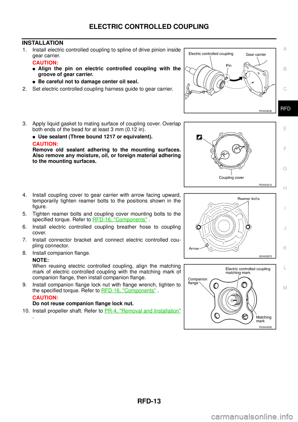
1. Install electric controlled coupling to spline of drive pinion inside
gear carrier.
CAUTION:
�Align the pin on electric controlled coupling with the
groove of gear carrier.
�Be careful not to damage center oil seal.
2. Set electric controlled coupling harness guide to gear carrier.
3. Apply liquid gasket to mating surface of coupling cover. Overlap
both ends of the bead for at least 3 mm (0.12 in).
�Use sealant (Three bound 1217 or equivalent).
CAUTION:
Remove old sealant adhering to the mounting surfaces.
Also remove any moisture, oil, or foreign material adhering
to the mounting surfaces.
4. Install coupling cover to gear carrier with arrow facing upward,
temporarily tighten reamer bolts to the positions shown in the
figure.
5. Tighten reamer bolts and coupling cover mounting bolts to the
specified torque. Refer to RFD-16, "
Components" .
6. Install electric controlled coupling breather hose to coupling
cover.
7. Install connector bracket and connect electric controlled cou-
pling connector.
8. Install companion flange.
NOTE:
When reusing electric controlled coupling, align the matching
mark of electric controlled coupling with the matching mark of
companion flange, then install companion flange.
9. Install companion flange lock nut with flange wrench, tighten to
the specified torque. Refer to RFD-16, "
Components" .
CAUTION:
Do not reuse companion flange lock nut.
10. Install propeller shaft. Refer to PR-4, "
Removal and Installation"
.
PDIA0463E
PDIA0451E
SDIA0587E
PDIA0455E
Page 2676 of 4179
RFD-16
REAR FINAL DRIVE ASSEMBLY
ComponentsEDS001ZB
PDIA0196E
1. Drive pinion 2. Pinion rear bearing 3. Drive pinion adjusting shim
4. Collapsible spacer 5. Gear carrier 6. Pinion front bearing
7. Drive pinion nut 8. Electric controlled coupling connec-
tor bracket9. Companion flange lock nut
10. Companion flange 11. Front oil seal 12. Coupling cover
13. Coupling front bearing 14. Electric controlled coupling 15. Center oil seal
16. Electric controlled coupling connec-
tor17. Side gear 18. Pinion mate shaft
19. Side gear thrust washer 20. Pinion mate thrust washer 21. Pinion mate gear
22. Lock pin 23. Side oil seal 24. Side bearing adjusting shim
25. Side bearing 26. Differential case 27. Drive gear
Page 2682 of 4179
RFD-22
REAR FINAL DRIVE ASSEMBLY
Disassembly and AssemblyEDS001ZD
DISASSEMBLY
Removal of Electric Controlled Coupling Assembly
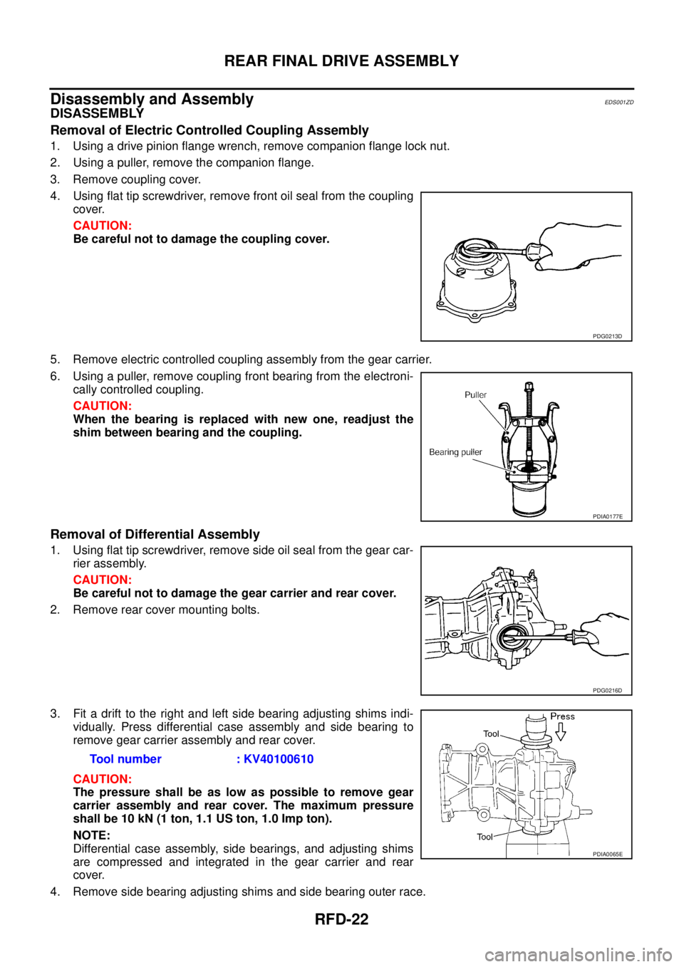
1. Using a drive pinion flange wrench, remove companion flange lock nut.
2. Using a puller, remove the companion flange.
3. Remove coupling cover.
4. Using flat tip screwdriver, remove front oil seal from the coupling
cover.
CAUTION:
Be careful not to damage the coupling cover.
5. Remove electric controlled coupling assembly from the gear carrier.
6. Using a puller, remove coupling front bearing from the electroni-
cally controlled coupling.
CAUTION:
When the bearing is replaced with new one, readjust the
shim between bearing and the coupling.
Removal of Differential Assembly
1. Using flat tip screwdriver, remove side oil seal from the gear car-
rier assembly.
CAUTION:
Be careful not to damage the gear carrier and rear cover.
2. Remove rear cover mounting bolts.
3. Fit a drift to the right and left side bearing adjusting shims indi-
vidually. Press differential case assembly and side bearing to
remove gear carrier assembly and rear cover.
CAUTION:
The pressure shall be as low as possible to remove gear
carrier assembly and rear cover. The maximum pressure
shall be 10 kN (1 ton, 1.1 US ton, 1.0 Imp ton).
NOTE:
Differential case assembly, side bearings, and adjusting shims
are compressed and integrated in the gear carrier and rear
cover.
4. Remove side bearing adjusting shims and side bearing outer race.
PDG0213D
PDIA0177E
PDG0216D
Tool number : KV40100610
PDIA0065E
Page 2683 of 4179
REAR FINAL DRIVE ASSEMBLY
RFD-23
C
E
F
G
H
I
J
K
L
MA
B
RFD
CAUTION:
Mark the side bearing adjusting shims so that the original mounting positions (right/left) can be
identified later.
5. Remove drive gear mounting bolts, and remove drive gear from the differential case.
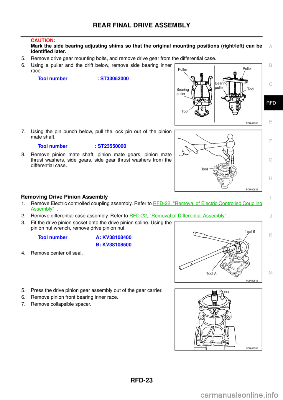
6. Using a puller and the drift below, remove side bearing inner
race.
7. Using the pin punch below, pull the lock pin out of the pinion
mate shaft.
8. Remove pinion mate shaft, pinion mate gears, pinion mate
thrust washers, side gears, side gear thrust washers from the
differential case.
Removing Drive Pinion Assembly
1. Remove Electric controlled coupling assembly. Refer to RFD-22, "Removal of Electric Controlled Coupling
Assembly" .
2. Remove differential case assembly. Refer to RFD-22, "
Removal of Differential Assembly" .
3. Fit the drive pinion socket onto the drive pinion spline. Using the
pinion nut wrench, remove drive pinion nut.
4. Remove center oil seal.
5. Press the drive pinion gear assembly out of the gear carrier.
6. Remove pinion front bearing inner race.
7. Remove collapsible spacer.Tool number : ST33052000
PDIA0178E
Tool number : ST23550000
PDIA0062E
Tool number A: KV38108400
B: KV38108500
PDIA0054E
SDIA0576E
Page 2689 of 4179
REAR FINAL DRIVE ASSEMBLY
RFD-29
C
E
F
G
H
I
J
K
L
MA
B
RFD
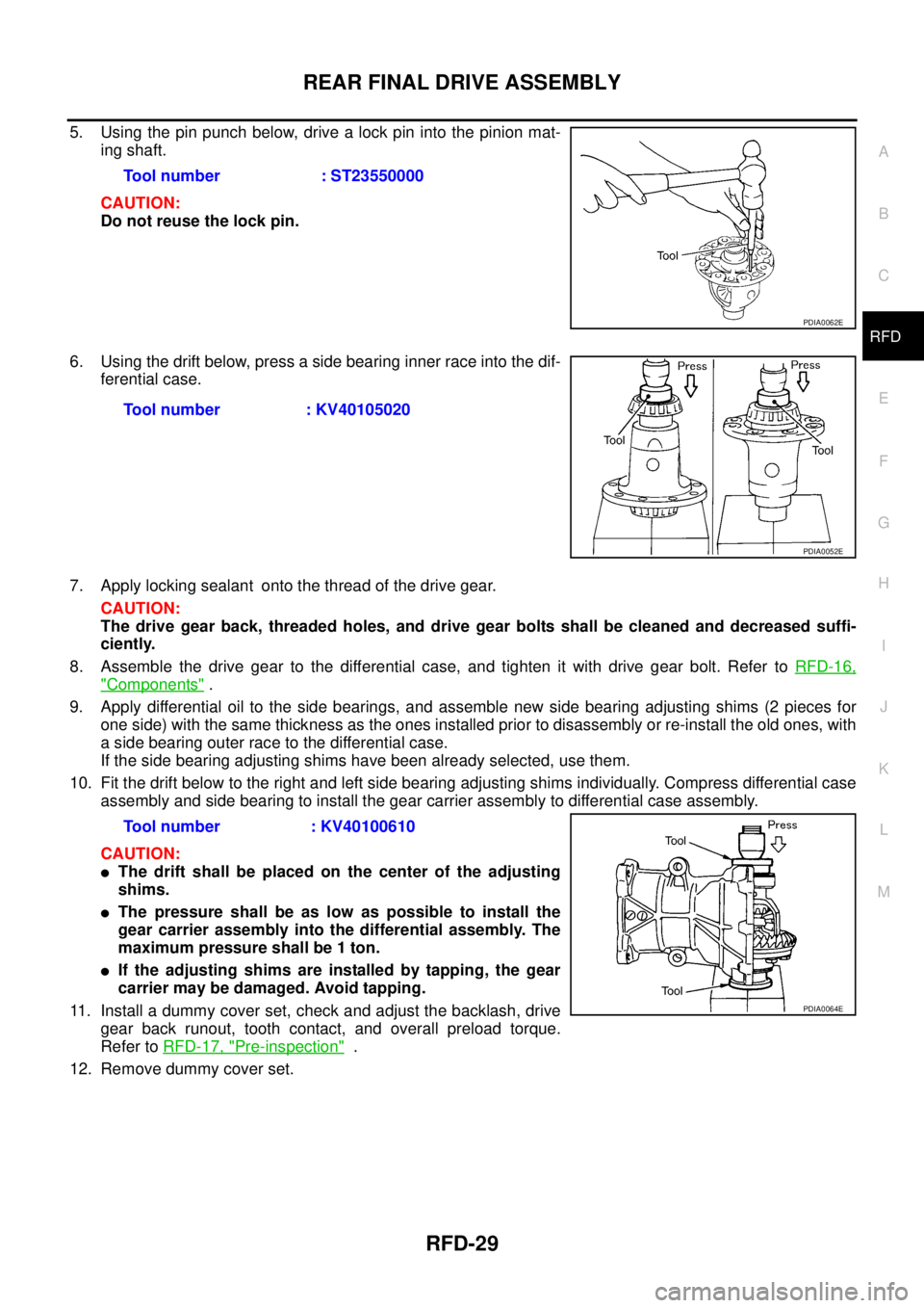
5. Using the pin punch below, drive a lock pin into the pinion mat-
ing shaft.
CAUTION:
Do not reuse the lock pin.
6. Using the drift below, press a side bearing inner race into the dif-
ferential case.
7. Apply locking sealant onto the thread of the drive gear.
CAUTION:
The drive gear back, threaded holes, and drive gear bolts shall be cleaned and decreased suffi-
ciently.
8. Assemble the drive gear to the differential case, and tighten it with drive gear bolt. Refer to RFD-16,
"Components" .
9. Apply differential oil to the side bearings, and assemble new side bearing adjusting shims (2 pieces for
one side) with the same thickness as the ones installed prior to disassembly or re-install the old ones, with
a side bearing outer race to the differential case.
If the side bearing adjusting shims have been already selected, use them.
10. Fit the drift below to the right and left side bearing adjusting shims individually. Compress differential case
assembly and side bearing to install the gear carrier assembly to differential case assembly.
CAUTION:
�The drift shall be placed on the center of the adjusting
shims.
�The pressure shall be as low as possible to install the
gear carrier assembly into the differential assembly. The
maximum pressure shall be 1 ton.
�If the adjusting shims are installed by tapping, the gear
carrier may be damaged. Avoid tapping.
11. Install a dummy cover set, check and adjust the backlash, drive
gear back runout, tooth contact, and overall preload torque.
Refer to RFD-17, "
Pre-inspection" .
12. Remove dummy cover set.Tool number : ST23550000
PDIA0062E
Tool number : KV40105020
PDIA0052E
Tool number : KV40100610
PDIA0064E
Page 2701 of 4179
FRONT WHEEL HUB AND KNUCKLE
FAX-7
C
E
F
G
H
I
J
K
L
MA
B
FA X
FRONT WHEEL HUB AND KNUCKLEPFP:40202
On-Vehicle InspectionEDS0005R
Inspect to check that there is no excessive play, cracking, wear, or
other damage to front axle.
�Turn front wheels (left/right) and check the play.
�Check that no nails or other foreign objects are embedded.
�Retighten all axle nuts and bolts to the specified torque.
FRONT WHEEL BEARINGS
With the vehicle raised, inspect the following.
�Move wheel hub in the axial direction by hand. Check that there is no looseness of front wheel bearings.
�Rotate wheel hub and check that there is no unusual noise or other irregular conditions. If there are any
irregular conditions, replace the wheel bearing.
Removal and InstallationEDS0005S
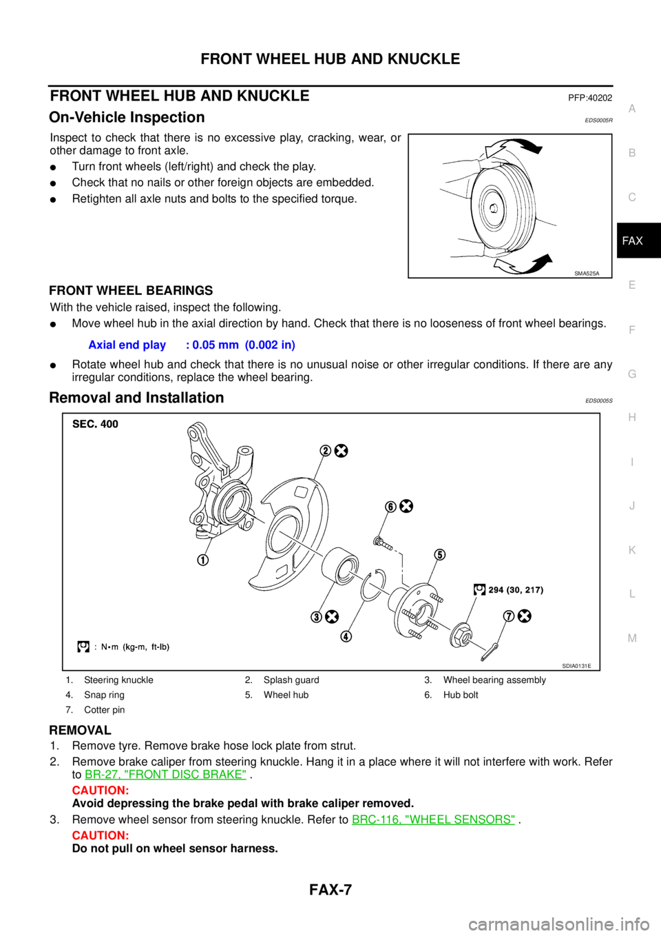
REMOVAL
1. Remove tyre. Remove brake hose lock plate from strut.
2. Remove brake caliper from steering knuckle. Hang it in a place where it will not interfere with work. Refer
to BR-27, "
FRONT DISC BRAKE" .
CAUTION:
Avoid depressing the brake pedal with brake caliper removed.
3. Remove wheel sensor from steering knuckle. Refer to BRC-116, "
WHEEL SENSORS" .
CAUTION:
Do not pull on wheel sensor harness.
SMA525A
Axial end play : 0.05 mm (0.002 in)
1. Steering knuckle 2. Splash guard 3. Wheel bearing assembly
4. Snap ring 5. Wheel hub 6. Hub bolt
7. Cotter pin
SDIA0131E
Page 2702 of 4179
FAX-8
FRONT WHEEL HUB AND KNUCKLE
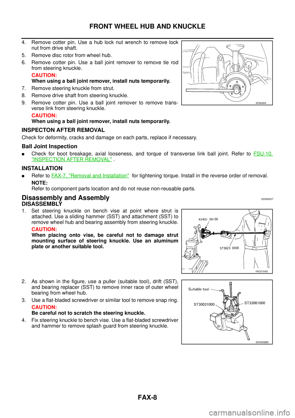
4. Remove cotter pin. Use a hub lock nut wrench to remove lock
nut from drive shaft.
5. Remove disc rotor from wheel hub.
6. Remove cotter pin. Use a ball joint remover to remove tie rod
from steering knuckle.
CAUTION:
When using a ball joint remover, install nuts temporarily.
7. Remove steering knuckle from strut.
8. Remove drive shaft from steering knuckle.
9. Remove cotter pin. Use a ball joint remover to remove trans-
verse link from steering knuckle.
CAUTION:
When using a ball joint remover, install nuts temporarily.
INSPECTON AFTER REMOVAL
Check for deformity, cracks and damage on each parts, replace if necessary.
Ball Joint Inspection
�Check for boot breakage, axial looseness, and torque of transverse link ball joint. Refer to FSU-10,
"INSPECTION AFTER REMOVAL" .
INSTALLATION
�Refer to FAX-7, "Removal and Installation" for tightening torque. Install in the reverse order of removal.
NOTE:
Refer to component parts location and do not reuse non-reusable parts.
Disassembly and AssemblyEDS0005T
DISASSEMBLY
1. Set steering knuckle on bench vise at point where strut is
attached. Use a sliding hammer (SST) and attachment (SST) to
remove wheel hub and bearing assembly from steering knuckle.
CAUTION:
When placing onto vise, be careful not to damage strut
mounting surface of steering knuckle. Use an aluminum
plate or another suitable tool.
2. As shown in the figure, use a puller (suitable tool), drift (SST),
and bearing replacer (SST) to remove inner race of outer wheel
bearing from wheel hub.
3. Use a flat-bladed screwdriver or similar tool to remove snap ring.
CAUTION:
Be careful not to scratch the steering knuckle.
4. Fix steering knuckle to bench vise. Use a flat-bladed screwdriver
and hammer to remove splash guard from steering knuckle.
SFA649A
FAC0104D
SDIA0588E
Page 2704 of 4179
FAX-10
FRONT WHEEL HUB AND KNUCKLE
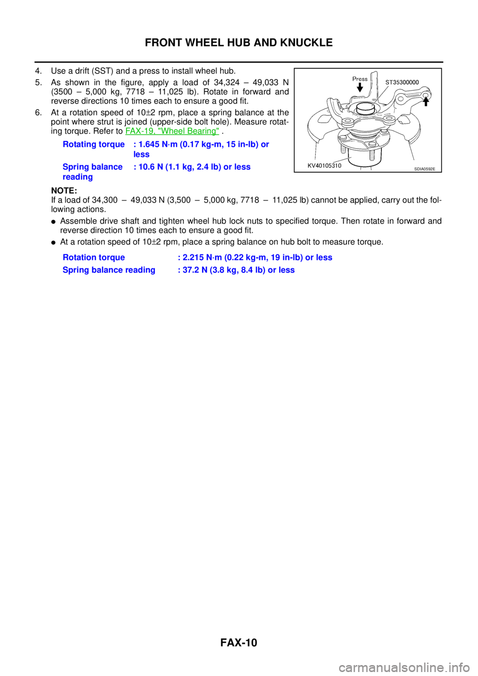
4. Use a drift (SST) and a press to install wheel hub.
5. As shown in the figure, apply a load of 34,324 – 49,033 N
(3500 – 5,000 kg, 7718 – 11,025 lb). Rotate in forward and
reverse directions 10 times each to ensure a good fit.
6. At a rotation speed of 10±2 rpm, place a spring balance at the
point where strut is joined (upper-side bolt hole). Measure rotat-
ing torque. Refer to FA X - 1 9 , "
Wheel Bearing" .
NOTE:
If a load of 34,300 – 49,033 N (3,500 – 5,000 kg, 7718 – 11,025 lb) cannot be applied, carry out the fol-
lowing actions.
�Assemble drive shaft and tighten wheel hub lock nuts to specified torque. Then rotate in forward and
reverse direction 10 times each to ensure a good fit.
�At a rotation speed of 10±2 rpm, place a spring balance on hub bolt to measure torque. Rotating torque : 1.645 N·m (0.17 kg-m, 15 in-lb) or
less
Spring balance
reading: 10.6 N (1.1 kg, 2.4 lb) or less
Rotation torque : 2.215 N·m (0.22 kg-m, 19 in-lb) or less
Spring balance reading : 37.2 N (3.8 kg, 8.4 lb) or less
SDIA0592E