2003 NISSAN X-TRAIL LIGHT ASSEMBLY
[x] Cancel search: LIGHT ASSEMBLYPage 9 of 3066

AT-3
D
E
F
G
H
I
J
K
L
MA
B
AT Line Pressure Test ............................................... 290
Road Test ............................................................. 291
TROUBLE DIAGNOSIS — GENERAL DESCRIP-
TION ........................................................................ 308
Symptom Chart .................................................... 308
TCM Terminals and Reference Value ................... 347
CAN COMMUNICATION ........................................ 351
System Description .............................................. 351
TROUBLE DIAGNOSES FOR SYMPTOMS .......... 352
............................................................................. 352
1. O/D OFF Indicator Lamp Does Not Come On . 354
2. Engine Cannot Be Started In “P” and “N” Position. 355
3. In “P” Position, Vehicle Moves Forward Or Back-
ward When Pushed .............................................. 356
4. In “N” Position, Vehicle Moves ......................... 356
5. Large Shock. “N”®“R” Position ...................... 358
6. Vehicle Does Not Creep Backward In “R” Position. 359
7. Vehicle Does Not Creep Forward In “D”, “2” Or
“1” Position ........................................................... 362
8. Vehicle Cannot Be Started From D
1................. 364
9. A/T Does Not Shift: D
1®D2Or Does Not Kick-
down: D
4®D2..................................................... 366
10. A/T Does Not Shift: D
2®D3......................... 368
11.A/TDoesNotShift:D
3®D4.......................... 371
12. A/T Does Not Perform Lock-up ...................... 374
13. A/T Does Not Hold Lock-up Condition ........... 375
14. Lock-up Is Not Released ................................ 376
15. Engine Speed Does Not Return To Idle (Light
Braking D
4®D3) ................................................ 377
16. Vehicle Does Not Start From D
1..................... 379
17. A/T Does Not Shift: D
4®D3, When Overdrive
Control Switch “ON”®“OFF” .............................. 380
18. A/T Does Not Shift: D
3®22, When Selector
Lever “D”®“2” Position ...................................... 380
19. A/T Does Not Shift: 2
2®11, When Selector
Lever “2”®“1” Position ....................................... 381
20. Vehicle Does Not Decelerate By Engine Brake. 381
21. TCM Self-diagnosis Does Not Activate (PNP &
Overdrive Control Switches, and Throttle Position
Sensor Circuit Checks) ........................................ 382
ALL
MAIN POWER SUPPLY AND GROUND CIRCUIT. 389
Wiring Diagram — AT — MAIN ............................ 389
Diagnostic Procedure ........................................... 390
VEHICLE SPEED SENSOR·A/T (REVOLUTION
SENSOR) ................................................................ 392
Description ........................................................... 392
Wiring Diagram — AT — VSSA/T ........................ 394
Diagnostic Procedure ........................................... 395
DTC VEHICLE SPEED SENSOR MTR .................. 397
Description ........................................................... 397
Wiring Diagram — AT — VSSMTR ...................... 399
Diagnostic Procedure ........................................... 400
ACCELE RATOR PEDAL POSITION (APP) SEN-
SOR ........................................................................ 401
Description ........................................................... 401Wiring Diagram — AT — TPS ..............................403
Diagnostic Procedure ...........................................404
SHIFT SOLENOID VALVE A ..................................406
Description ............................................................406
Wiring Diagram — AT — SSV/A ...........................408
Diagnostic Procedure ...........................................409
Component Inspection ..........................................410
SHIFT SOLENOID VALVE B ..................................411
Description ............................................................411
Wiring Diagram — AT — SSV/B ...........................413
Diagnostic Procedure ...........................................414
Component Inspection ..........................................415
OVERRUN CLUTCH SOLENOID VALVE ...............416
Description ............................................................416
Wiring Diagram — AT — OVRCSV ......................418
Diagnostic Procedure ...........................................419
Component Inspection ..........................................420
TORQUE CONVERTER CLUTCH SOLENOID
VALVE .....................................................................421
Description ............................................................421
Wiring Diagram — AT — TCV ..............................423
Diagnostic Procedure ...........................................424
Component Inspection ..........................................425
BATT/FLUID TEMP SEN (A/T FLUID TEMP SEN-
SOR CIRCUIT AND TCM POWER SOURCE) .......426
Description ............................................................426
Wiring Diagram — AT — BA/FTS .........................428
Diagnostic Procedure ...........................................429
Component Inspection ..........................................431
ENGINE SPEED SIGNAL .......................................432
Description ............................................................432
Wiring Diagram — AT — ENGSS .........................433
Diagnostic Procedure ...........................................434
LINE PRESSURE SOLENOID VALVE ...................436
Description ............................................................436
Wiring Diagram — AT — LPSV ............................438
Diagnostic Procedure ...........................................439
Component Inspection ..........................................441
CAN CAMMUNICATION LINE ................................443
Description ............................................................443
On Board Diagnosis Logic ....................................443
Self-Diagnosis Code Confirmation Procedure ......443
Wiring Diagram — AT — CAN ..............................444
Diagnostic Procedure ...........................................445
A/T SHIFT LOCK SYSTEM ....................................446
Description ............................................................446
Shift Lock System Electrical Parts Location .........446
Wiring Diagram — SHIFT — ................................447
Diagnostic Procedure ...........................................448
KEY INTERLOCK CABLE ......................................452
Components .........................................................452
Removal ...............................................................452
Installation ............................................................453
ON-VEHICLE SERVICE ..........................................454
Control Valve Assembly and Accumulators ..........454
Control Cable Adjustment .....................................456
Park/Neutral Position (PNP) Switch Adjustment ..456
Page 475 of 3066
![NISSAN X-TRAIL 2003 Electronic Repair Manual DISASSEMBLY
AT-469
[ALL]
D
E
F
G
H
I
J
K
L
MA
B
AT
14. Remove N-D accumulator piston and return spring with com-
pressed air.
15. Remove O-rings from N-D accumulator piston.
16. Check accumulator pist](/manual-img/5/57402/w960_57402-474.png "NISSAN X-TRAIL 2003 Electronic Repair Manual DISASSEMBLY
AT-469
[ALL]
D
E
F
G
H
I
J
K
L
MA
B
AT
14. Remove N-D accumulator piston and return spring with com-
pressed air.
15. Remove O-rings from N-D accumulator piston.
16. Check accumulator pist")
DISASSEMBLY
AT-469
[ALL]
D
E
F
G
H
I
J
K
L
MA
B
AT
14. Remove N-D accumulator piston and return spring with com-
pressed air.
15. Remove O-rings from N-D accumulator piston.
16. Check accumulator pistons and contact surface of transmission
case for damage.
17. Check accumulator return springs for damage and free length.
18. Remove lip seals.
19. Remove L & R oil tube and oil sleeve.
20. Remove converter housing according to the following proce-
dures.
a. Remove converter housing mounting bolts.
b. Remove converter housing by tapping it lightly.
SAT020D
SAT023DA
SAT006F
SAT862HA
SAT008F
Page 485 of 3066
![NISSAN X-TRAIL 2003 Electronic Repair Manual DISASSEMBLY
AT-479
[ALL]
D
E
F
G
H
I
J
K
L
MA
B
AT
b. Remove side cover by lightly tapping it with a soft hammer.
lBe careful not to drop output shaft assembly. It might
come out when removing side co](/manual-img/5/57402/w960_57402-484.png "NISSAN X-TRAIL 2003 Electronic Repair Manual DISASSEMBLY
AT-479
[ALL]
D
E
F
G
H
I
J
K
L
MA
B
AT
b. Remove side cover by lightly tapping it with a soft hammer.
lBe careful not to drop output shaft assembly. It might
come out when removing side co")
DISASSEMBLY
AT-479
[ALL]
D
E
F
G
H
I
J
K
L
MA
B
AT
b. Remove side cover by lightly tapping it with a soft hammer.
lBe careful not to drop output shaft assembly. It might
come out when removing side cover.
c. Remove adjusting shim.
d. Remove output shaft assembly.
lIf output shaft assembly came off with side cover, tap cover
with a soft hammer to separate.
SAT434D
SAT440D
SAT035F
SAT435D
Page 505 of 3066
![NISSAN X-TRAIL 2003 Electronic Repair Manual REPAIR FOR COMPONENT PARTS
AT-499
[ALL]
D
E
F
G
H
I
J
K
L
MA
B
AT
DISASSEMBLY
1. Remove valves at retainer plates.
lDo not use a magnetic pick-up tool.
a. Use a screwdriver to remove retainer plates.](/manual-img/5/57402/w960_57402-504.png "NISSAN X-TRAIL 2003 Electronic Repair Manual REPAIR FOR COMPONENT PARTS
AT-499
[ALL]
D
E
F
G
H
I
J
K
L
MA
B
AT
DISASSEMBLY
1. Remove valves at retainer plates.
lDo not use a magnetic pick-up tool.
a. Use a screwdriver to remove retainer plates.")
REPAIR FOR COMPONENT PARTS
AT-499
[ALL]
D
E
F
G
H
I
J
K
L
MA
B
AT
DISASSEMBLY
1. Remove valves at retainer plates.
lDo not use a magnetic pick-up tool.
a. Use a screwdriver to remove retainer plates.
b. Remove retainer plates while holding spring, plugs or sleeves.
lRemove plugs slowly to prevent internal parts from jump-
ing out.
c. Place mating surface of valve body face down, and remove
internal parts.
lIf a valve is hard to remove, place valve body face down
and lightly tap it with a soft hammer.
lBe careful not to drop or damage valves and sleeves.
SAT551G
SAT553G
SAT554G
SAT137D
Page 548 of 3066
![NISSAN X-TRAIL 2003 Electronic Repair Manual AT-542
[ALL]
ASSEMBLY
9. Remove converter housing from transmission case.
10. Remove final drive assembly from transmission case.
11. Remove differential side bearing outer race from transmission
case](/manual-img/5/57402/w960_57402-547.png "NISSAN X-TRAIL 2003 Electronic Repair Manual AT-542
[ALL]
ASSEMBLY
9. Remove converter housing from transmission case.
10. Remove final drive assembly from transmission case.
11. Remove differential side bearing outer race from transmission
case")
AT-542
[ALL]
ASSEMBLY
9. Remove converter housing from transmission case.
10. Remove final drive assembly from transmission case.
11. Remove differential side bearing outer race from transmission
case.
12. Reinstall differential side bearing outer race and shim(s)
selected from SDS table on transmission case.
13. Reinstall converter housing on transmission case and tighten
transmission case fixing bolts to the specified torque. Refer to
AT-461, "
OVERHAUL".
14. Insert Tool and measure turning torque of final drive assembly.
lTurn final drive assembly in both directions several times
to seat bearing rollers correctly.
lWhen old bearing is used again, turning torque will be
slightly less than the above.
lMake sure torque is close to the specified range.
REDUCTION PINION GEAR BEARING PRELOAD
1. Remove transmission case and final drive assembly from con-
verter housing.
2. Select proper thickness of reduction pinion gear bearing adjust-
ing shim using the following procedures.
a. Place reduction pinion gear on transmission case as shown.
b. Place idler gear bearing on transmission case.
c. Measure dimensions “B” “C” and “D” and calculate dimension
“A”.
SAT010FC
Turning torque of final drive assembly (New bearing) :
0.78 - 1.37 N-m (8.0 - 14.0 kg-cm, 6.9 - 12.2 in-lb)
Preload adapter : KV38105210
SAT188FA
SAT332DA
A=D-(B + C)
“A” : Distance between the surface of idler gear bear-
ing inner race and the adjusting shim mating
surface of reduction pinion gear.
SAT333DA
Page 719 of 3066
REFRIGERANT LINES
ATC-141
C
D
E
F
G
H
I
K
L
MA
B
AT C
CAUTION:
Moving the electronic leak detector probe slower and closer to the suspected leak area will improve
the chances of finding a leak.
Checking System for Leaks Using the Fluorescent Leak DetectorEJS000VK
1. Check A/C system for leaks using the UV lamp and safety glasses (J-42220) in a low sunlight area (area
without windows preferable). Illuminate all components, fittings and lines. The dye will appear as a bright
green/yellow area at the point of leakage. Fluorescent dye observed at the evaporator drain opening indi-
cates an evaporator core assembly (tubes, core or TXV) leak.
2. If the suspected area is difficult to see, use an adjustable mirror or wipe the area with a clean shop rag or
cloth, with the UV lamp for dye residue.
3. After the leak is repaired, remove any residual dye using dye cleaner (J-43872) to prevent future misdiag-
nosis.
4. Perform a system performance check and verify the leak repair with an approved electronic refrigerant
leak detector.
NOTE:
Other gases in the work area or substances on the A/C components, for example, anti-freeze, windshield
washer fluid, solvents and lubricants, may falsely trigger the leak detector. Make sure the surfaces to be
checked are clean.
Clean with a dry cloth or blow off with shop air.
Do not allow the sensor tip of the detector to contact with any substance. This can also cause false readings
and may damage the detector.
Dye InjectionEJS000VL
(This procedure is only necessary when recharging the system or when the compressor has seized and was
replaced.)
1. Check A/C system static (at rest) pressure. Pressure must be at least 345 kPa (50 psi).
2. Pour one bottle (1/4 ounce / 7.4 cc) of the A/C refrigerant dye into the injector tool (J-41459).
3. Connect the injector tool to the A/C LOW PRESSURE side service fitting.
4. Start engine and switch A/C ON.
5. When the A/C operating (compressor running), inject one bottle (1/4 ounce / 7.4 cc) of fluorescent dye
through the low-pressure service valve using dye injector tool J-41459 (refer to the manufacture's operat-
ing instructions).
6. With the engine still running, disconnect the injector tool from the service fitting.
CAUTION:
Be careful the A/C system or replacing a component, pour the dye directly into the open system con-
nection and proceed with the service procedures.
7. Operate the A/C system for a minimum of 20 minutes to mix the dye with the system oil. Depending on the
leak size, operating conditions and location of the leak, it may take from minutes to days for the dye to
penetrate a leak and become visible.
Electronic Refrigerant Leak DetectorEJS000VM
PRECAUTIONS FOR HANDLING LEAK DETECTOR
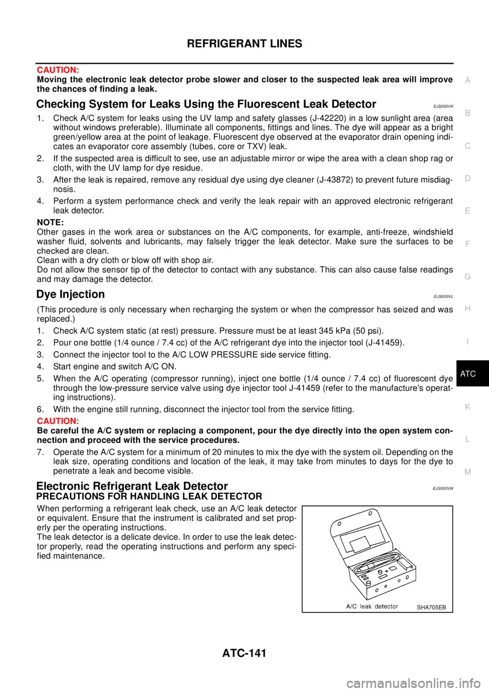
When performing a refrigerant leak check, use an A/C leak detector
or equivalent. Ensure that the instrument is calibrated and set prop-
erly per the operating instructions.
The leak detector is a delicate device. In order to use the leak detec-
tor properly, read the operating instructions and perform any speci-
fied maintenance.
SHA705EB
Page 749 of 3066

HOOD
BL-5
C
D
E
F
G
H
J
K
L
MA
B
BL
3. Confirm secondary latch is securely engaged with secondary
striker by releasing it from a height of approximately 200 mm
(7.87 in) or by pressing it lightly approx.3kg (29 N).
NOTE:
Do not release hood from a height of 300 mm (11.81 in) or
higher.
4. Move hood lock up and down until striker smoothly engages the
lock when the hood is closed.
5. After adjustment, tighten lock mount bolts to the specified
torque.
Removal and Installation of Hood AssemblyEIS000KG
1. Disconnect washer hose at the connection.
2. Remove hinge mount nuts on the hood and then the hood assembly.
PIIA0181E
SIIA0154E
Page 874 of 3066
![NISSAN X-TRAIL 2003 Electronic Repair Manual BRC-6
[4WD/ABS]
ALL MODE 4X4 SYSTEM
ALL MODE 4X4 SYSTEM
PFP:47850
System DescriptionEFS001CJ
ABS FUNCTION
lDuring ABS operation, brake pedal lightly vibrates and its mechanical noise may be heard. Thi](/manual-img/5/57402/w960_57402-873.png "NISSAN X-TRAIL 2003 Electronic Repair Manual BRC-6
[4WD/ABS]
ALL MODE 4X4 SYSTEM
ALL MODE 4X4 SYSTEM
PFP:47850
System DescriptionEFS001CJ
ABS FUNCTION
lDuring ABS operation, brake pedal lightly vibrates and its mechanical noise may be heard. Thi")
BRC-6
[4WD/ABS]
ALL MODE 4X4 SYSTEM
ALL MODE 4X4 SYSTEM
PFP:47850
System DescriptionEFS001CJ
ABS FUNCTION
lDuring ABS operation, brake pedal lightly vibrates and its mechanical noise may be heard. This is a nor-
mal condition.
lWhen starting engine, or just after starting vehicle, brake pedal may vibrate. Also motor operating noise
may be heard from engine compartment. This is a normal status of operation check.
lWhen vehicle drives on rough, gravel, or snowy (fresh deep snow) road, the following conditions occur.
Stopping distance may be longer than that of vehicles without ABS.
4WD FUNCTION
lElectronically controlled 4WD is controlled by the same control module as that for ABS (4WD/ABS control
unit). 4WD/ABS control unit controls both electronically-controlled 4WD and ABS, based on input signals
from several sensors.
lIf electrical system-related malfunction occurred in 4WD/ABS system, control unit illuminates the following
lamps: 4WD warning lamp and/or ABS warning lamp on meter control unit assembly. This notifies driver of
malfunction. At the same time, control unit indicates malfunctioning part detected by self-diagnosis with
flashing pattern of LED. Indication on electronic system diagnosis tester (CONSULT) corresponds to this
flashing pattern as shown below.
Control System DiagramEFS001CK
Self-diagnostic test mode Remarks
Result of self-diagnosis Conformable to 4WD/ABS
Data monitor Conformable to 4WD/ABS
Active testChecks ABS solenoid valve ON/OFF, ABS motor ON/OFF, 4WD sole-
noid
Control unit part No. 4WD/ABS control unit
SFIA0350E