2003 NISSAN X-TRAIL LIGHT ASSEMBLY
[x] Cancel search: LIGHT ASSEMBLYPage 2138 of 3066
![NISSAN X-TRAIL 2003 Electronic Repair Manual EM-168
[YD22DDTi]
PRIMARY TIMING CHAIN
INSPECTION AFTER REMOVAL
Timing Chain
Check for cracks and excessive wear at roller links. Replace
chain if necessary.
INSTALLATION
1. Install rear chain case.
a](/manual-img/5/57402/w960_57402-2137.png "NISSAN X-TRAIL 2003 Electronic Repair Manual EM-168
[YD22DDTi]
PRIMARY TIMING CHAIN
INSPECTION AFTER REMOVAL
Timing Chain
Check for cracks and excessive wear at roller links. Replace
chain if necessary.
INSTALLATION
1. Install rear chain case.
a")
EM-168
[YD22DDTi]
PRIMARY TIMING CHAIN
INSPECTION AFTER REMOVAL
Timing Chain
Check for cracks and excessive wear at roller links. Replace
chain if necessary.
INSTALLATION
1. Install rear chain case.
a. Apply a continuous bead of Genuine Liquid Gasket or eqivalent
on locations shown in the figure. Refer toEM-103, "
Precautions
for Liquid Gasket".
A: Apply bead so that it does not protrude into the oil passage.
B, C: Minimize overlapping area of bead, by starting and ending
at areas of bead as shown in the figure. Apply so that the portion
marked * comes at an external location but cannot be viewed
externally after engine assembly.
D: Leave the start and end areas of the bead slightly protruding
from the case surface.
SEM984C
JEM139G
SBIA0212E
Page 2247 of 3066
FSU-8
COIL SPRING AND SHOCK ABSORBER
COIL SPRING AND SHOCK ABSORBER
PFP:54302
Removal and InstallationEES00074
REMOVAL
1. Remove tires. Remove brake caliper and hung it aside.
CAUTION:
Avoid depressing brake pedal with brake caliper removed.
2. Remove electrical wires of ABS wheel speed sensor from strut.
3. Remove brake hose lock plate.
4. Remove mounting bolts and nuts securing steering knuckle to strut.
5. Remove mounting nuts on top of strut and remove upper mounting plate and strut from vehicle.
INSTALLATION
lRefer toFSU-5, "Components"in “Front Suspension Assembly” for tightening torque. Tighten in the
reverse order of removal.
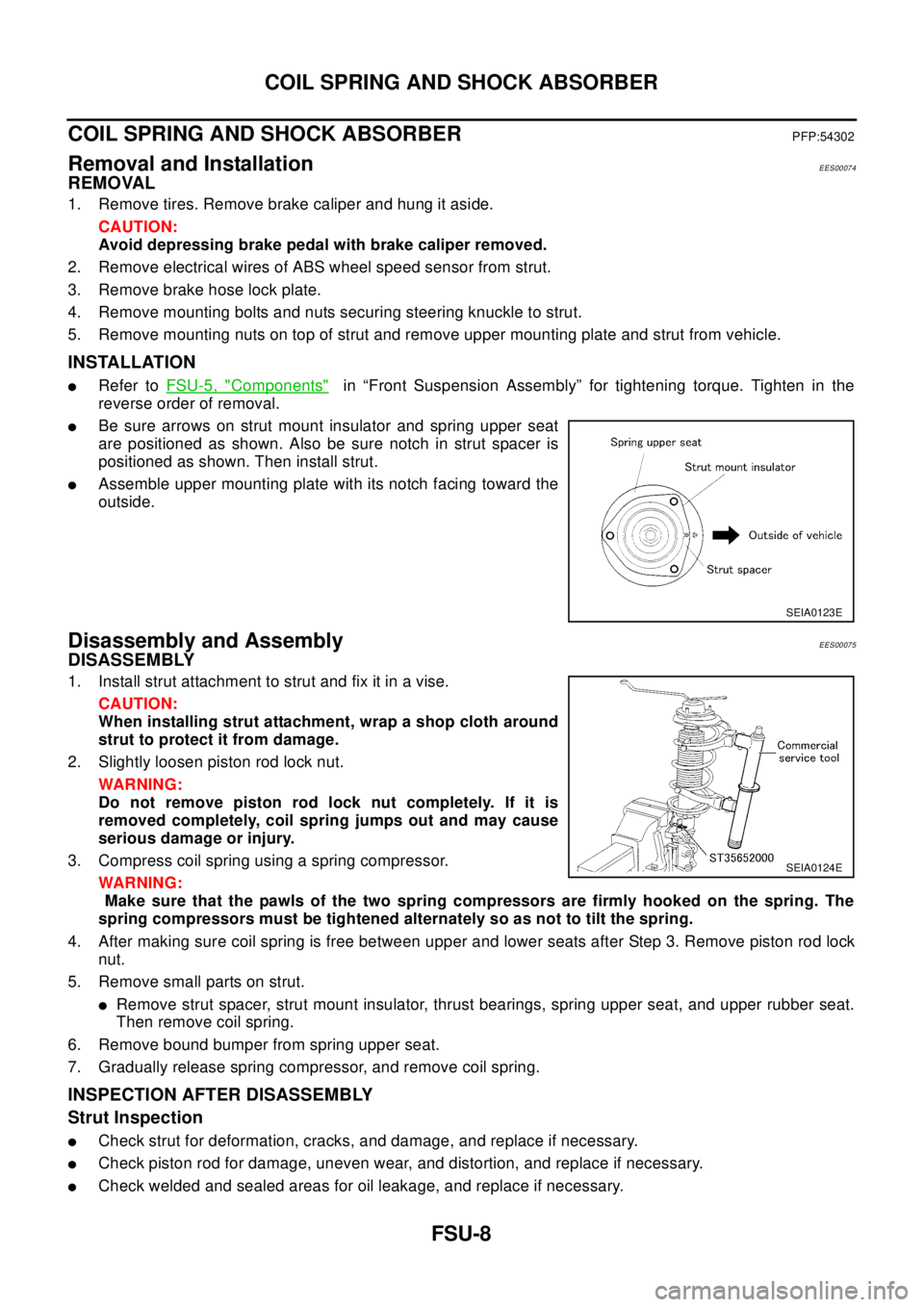
lBe sure arrows on strut mount insulator and spring upper seat
are positioned as shown. Also be sure notch in strut spacer is
positioned as shown. Then install strut.
lAssemble upper mounting plate with its notch facing toward the
outside.
Disassembly and AssemblyEES00075
DISASSEMBLY
1. Install strut attachment to strut and fix it in a vise.
CAUTION:
When installing strut attachment, wrap a shop cloth around
strut to protect it from damage.
2. Slightly loosen piston rod lock nut.
WAR NIN G:
Do not remove piston rod lock nut completely. If it is
removed completely, coil spring jumps out and may cause
serious damage or injury.
3. Compress coil spring using a spring compressor.
WAR NIN G:
Make sure that the pawls of the two spring compressors are firmly hooked on the spring. The
spring compressors must be tightened alternately so as not to tilt the spring.
4. After making sure coil spring is free between upper and lower seats after Step 3. Remove piston rod lock
nut.
5. Remove small parts on strut.
lRemove strut spacer, strut mount insulator, thrust bearings, spring upper seat, and upper rubber seat.
Then remove coil spring.
6. Remove bound bumper from spring upper seat.
7. Gradually release spring compressor, and remove coil spring.
INSPECTION AFTER DISASSEMBLY
Strut Inspection
lCheck strut for deformation, cracks, and damage, and replace if necessary.
lCheck piston rod for damage, uneven wear, and distortion, and replace if necessary.
lCheck welded and sealed areas for oil leakage, and replace if necessary.
SEIA0123E
SEIA0124E
Page 2249 of 3066
FSU-10
TRANSVERSE LINK
TRANSVERSE LINK
PFP:54500
Removal and InstallationEES00076
REMOVAL
1. Remove steering knuckle from transverse link. Refer toFAX-7, "REMOVAL".
2. Remove mounting nuts and washers on lower portion of stabilizer connecting rod.
3. Slightly loosen transverse link mounting bolts.
4. Remove compression rod bracket mounting bolts.
5. Remove transverse link mounting bolts and nuts, and remove transverse link from suspension member.
INSPECTION AFTER REMOVAL
Visual Inspection
Check transverse link and bushing for deformation, cracks, and other damage. Replace the entire transverse
link assembly if cracks, deformation or any other damage is found.
Ball Joint Inspection
CAUTION:
Before measurement, move the ball joint at least ten times by hand to check for smooth movement.
Oscillating Torque Inspection
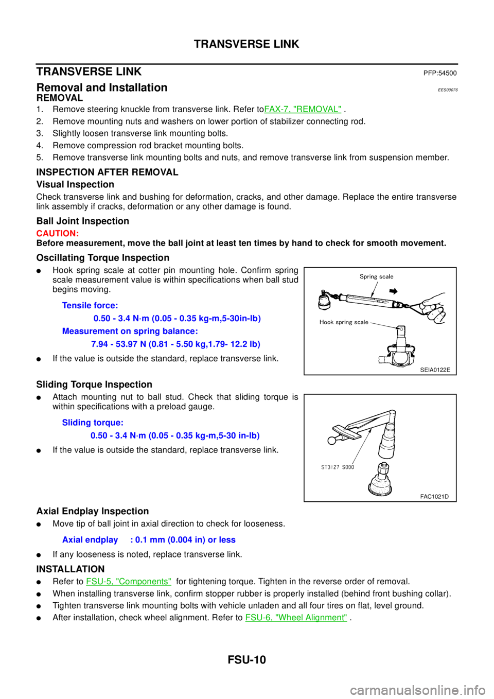
lHook spring scale at cotter pin mounting hole. Confirm spring
scale measurement value is within specifications when ball stud
begins moving.
lIf the value is outside the standard, replace transverse link.
Sliding Torque Inspection
lAttach mounting nut to ball stud. Check that sliding torque is
within specifications with a preload gauge.
lIf the value is outside the standard, replace transverse link.
Axial Endplay Inspection
lMove tip of ball joint in axial direction to check for looseness.
lIf any looseness is noted, replace transverse link.
INSTALLATION
lRefer toFSU-5, "Components"for tightening torque. Tighten in the reverse order of removal.
lWhen installing transverse link, confirm stopper rubber is properly installed (behind front bushing collar).
lTighten transverse link mounting bolts with vehicle unladen and all four tires on flat, level ground.
lAfter installation, check wheel alignment. Refer toFSU-6, "Wheel Alignment". Tensile force:
0.50 - 3.4 N·m (0.05 - 0.35 kg-m,5-30in-lb)
Measurement on spring balance:
7.94 - 53.97 N (0.81 - 5.50 kg,1.79- 12.2 lb)
SEIA0122E
Sliding torque:
0.50 - 3.4 N·m (0.05 - 0.35 kg-m,5-30 in-lb)
FAC1021D
Axial endplay : 0.1 mm (0.004 in) or less
Page 2271 of 3066

GI-18
HOW TO USE THIS MANUAL
13 ConnectorslThis shows that the connector is connected to the body or a terminal with bolt or nut.
14 Wire color
lThis shows a code for the color of the wire.
B=Black
W=White
R=Red
G=Green
L=Blue
Y=Yellow
LG = Light GreenBR = Brown
OR = Orange
P=Pink
PU = Purple
GY = Gray
SB = Sky Blue
CH = Dark Brown
DG = Dark Green
When the wire color is striped, the base color is given first, followed by the stripe color as shown
below:
Example: L/W = Blue with White Stripe
15 Option description
lThis shows a description of the option abbreviation used on the page.
16 Switch
lThis shows that continuity exists between terminals 1 and 2 when the switch is in the A posi-
tion. Continuity exists between terminals 1 and 3 when the switch is in the B position.
17 Assembly parts
lConnector terminal in component shows that it is a harness incorporated assembly.
18 Cell code
lThis identifies each page of the wiring diagram by section, system and wiring diagram page
number.
19 Current flow arrow
lArrow indicates electric current flow, especially where the direction of standard flow (vertically
downward or horizontally from left to right) is difficult to follow.
lA double arrow “ ” shows that current can flow in either direction depending on cir-
cuit operation.
20 System branch
lThis shows that the system branches to another system identified by cell code (section and
system).
21 Page crossing
lThis arrow shows that the circuit continues to another page identified by cell code.
lThe C will match with the C on another page within the system other than the next or preced-
ing pages.
22 Shielded line
lThe line enclosed by broken line circle shows shield wire.
23Component box in
wave line
lThis shows that another part of the component is also shown on another page (indicated by
wave line) within the system.
24 Component name
lThis shows the name of a component.
25 Connector number
lThis shows the connector number.
lThe letter shows which harness the connector is located in.
lExample:M: main harness. For detail and to locate the connector, refer to PG section "Main
Harness", “Harness Layout”. A coordinate grid is included for complex harnesses to aid in
locating connectors.
26 Ground (GND)
lThe line spliced and grounded under wire color shows that ground line is spliced at the
grounded connector.
27 Ground (GND)
lThis shows the ground connection. For detailed ground distribution information, refer to
"Ground Distribution" in PG section.
28 Connector views
lThis area shows the connector faces of the components in the wiring diagram on the page.
29 Common component
lConnectors enclosed in broken line show that these connectors belong to the same compo-
nent.
30 Connector color
lThis shows a code for the color of the connector. For code meaning, refer to wire color codes,
Number 14 of this chart. Num-
berItem Description
Page 2360 of 3066
IDX-3
A
C
D
E
F
G
H
I
J
K
L B
IDX
ALPHABETICAL INDEX
Brake fluid level and line check ...........................BR-9
Brake hydraulic line ...........................................BR-11
Brake inspection ................................................MA-39
Brake lines and cables inspection .....................MA-39
Brake master cylinder ........................................BR-13
Brake pedal .........................................................BR-6
Brake switch ........................EC-329,EC-562,EC-810
BRK/SW - Wiring diagram ...EC-330,EC-564,EC-811
Bulb specifications ..............................................LT-67
Bumper, front .........................................................EI-6
Bumper, rear ..........................................................EI-9
C
Camshaft inspection(QR20DE) .........................EM-38
Camshaft inspection(YD22DDTi) ....................EM-150
Camshaft position sensor (CMPS) ..................EC-739
Camshaft position sensor (PHASE) ..EC-223,EC-507
Camshaft(QR20DE) ..........................................EM-33
Camshaft(YD22DDTi) ......................................EM-149
CAN - Wiring diagramEC-115,EC-461,LAN-6,LAN-12
CAN (Controller Area Network) .........AT-129,AT-351,
LAN-3
,LAN-5,LAN-11
CAN Communication ..........................................TF-53
CAN communicationEC-28,EC-114,EC-393,EC-460,
AT-129
,AT-351,BRC-53,BRC-59,BRC-90,BRC-108,
LAN-3
,LAN-5,LAN-11
Canister-See EVAP canister .............EC-374,EC-649
CHARGE - Wiring diagram ................................SC-13
Charging system ................................................SC-12
Chassis and body maintenance ........................MA-35
CHIME - Wiring diagram .....................................DI-54
CIGAR - Wiring diagram ..................................WW-25
Cigarette lighter ...............................................WW-25
Circuit breaker ...................................................PG-12
CKPS - Wiring diagram ...................................EC-736
Clearance lamp ........................................LT-4,LT-40
Clock ...................................................................DI-60
CLOCK - Wiring diagram ....................................DI-60
Closed loop control ..............................EC-25,EC-390
Clutch cover .......................................................CL-15
Clutch disc .........................................................CL-15
Clutch master cylinder .........................................CL-9
Clutch operating cylinder ...................................CL-11
Clutch pedal .........................................................CL-5
Clutch release bearing .......................................CL-13
Clutch release mechanism ................................CL-13
Clutch withdrawal lever ......................................CL-13
CMPS - Wiring diagram ...................................EC-741
Coil spring (rear) ...............................................RSU-8
Collision diagnosis ...........................................SRS-46
Combination meter .....................................DI-4,DI-22
Combination switch ................................LT-24,LT-44
Common rail fuel pressure sensor ...................EC-723
Component Location (auto A/C) .........ATC-31,MTC-4
Compression pressure(QR20DE) ......................EM-52
Compression pressure(YD22DDTi) .................EM-173
Compressor clutch removal and installation ..ATC-129
Compressor special service tool ......................ATC-11
Condenser .....................................................ATC-138
Connecting rod bearing clearance(QR20DE) ...EM-83
Connecting rod bearing clearance(YD22DDTi)EM-206
Connecting rod bushing clearance(QR20DE) ..EM-83
Connecting rod bushing clearance(YD22DDTi)EM-200
Connecting rod(QR20DE) .................................EM-82
Connecting rod(YD22DDTi) ..............EM-198,EM-202
Console box - See Instrument panel ..........IP-3,IP-10
CONSULT for engine ............EC-86,EC-434,EC-691
CONSUT for VDC ...........................................BRC-77
Control unit .....................................ATC-104,MTC-19
Control units (terminal arrangement) .................PG-73
Controller Area Network (CAN) ........AT-129,AT-351,
LAN-3
,LAN-5,LAN-11
Converter housing installation ...........AT-459,AT-556
COOL/F - Wiring diagram ...EC-315,EC-552,EC-763
Coolant mixture ratio .........................................MA-19
Coolant replacement(QR20DE) ........................MA-20
Coolant replacement(YD22DDTi) .....................MA-27
Cooling circuit (engine)(QR20DE) ......................CO-7
Cooling circuit (engine)(YD22DDTi) .................CO-28
Cooling fan control system(QR20DE) ...............CO-13
Cooling fan motor ..............................EC-324,EC-561
Cooling fan relay ................................EC-324,EC-561
Cooling fan(QR20DE) .......................................CO-13
Cooling fan(YD22DDTi) ....................................CO-34
Coupling sleeve (M/T) ...........................MT-19,MT-24
Cowl top ..............................................................EI-12
Cowl top cover ....................................................EI-12
Crankcase ventilation system ..........................EC-663
Crankcase ventilation system - See Positive crankcase
ventilation ...........................................EC-375
,EC-650
Crankshaft position sensor (POS) .....EC-217,EC-501
Crankshaft position sensor (TDC) ...................EC-734
Crankshaft(QR20DE) ........................................EM-65
Crankshaft(YD22DDTi) ...................................EM-200
CRFPS - Wiring diagram .................................EC-724
Cylinder block boring(QR20DE) .......................EM-86
Cylinder block boring(YD22DDTi) ...................EM-204
Cylinder block(QR20DE) ..................................EM-64
Cylinder block(YD22DDTi) ..............................EM-188
Cylinder head bolt tightening(QR20DE) ...........EM-54
Cylinder head bolt tightening(YD22DDTi) .......EM-175
Cylinder head gasket selection(YD22DDTi) ...EM-175
Cylinder head(QR20DE) ...................................EM-52
Cylinder head(YD22DDTi) ..............................EM-173
D
Data link connector ............................EC-371
,EC-646
Data link connector for Consult ...........EC-88,EC-435,
EC-691
Daytime light system .............................................LT-9
Daytime running light - See Daytime light systemLT-9
DEF - Wiring diagram .......................................GW-10
Desiccant Assembly .......................ATC-27,ATC-140
Diagnosis sensor unit .....................................SRS-39
Page 2405 of 3066
HEADLAMP
LT-7
C
D
E
F
G
H
I
J
L
MA
B
LT
CAUTION:
Be sure aiming switch is set to “0” when performing aiming adjustment.
LOW BEAM
1. Turn headlamp low beam on.
LHD models
RHD models
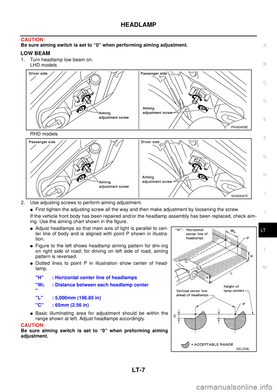
2. Use adjusting screws to perform aiming adjustment.
lFirst tighten the adjusting screw all the way and then make adjustment by loosening the screw.
If the vehicle front body has been repaired and/or the headlamp assembly has been replaced, check aim-
ing. Use the aiming chart shown in the figure.
lAdjust headlamps so that main axis of light is parallel to cen-
ter line of body and is aligned with point P shown in illustra-
tion.
lFigure to the left shows headlamp aiming pattern for driv-ing
on right side of road; for driving on left side of road, aiming
pattern is reversed.
lDotted lines to point P in illustration show center of head-
lamp.
lBasic illuminating area for adjustment should be within the
range shown at left. Adjust headlamps accordingly.
CAUTION:
Be sure aiming switch is set to “0” when preforming aiming
adjustment."H" : Horizontal center line of headlamps
"W
L
": Distance between each headlamp center
"L" : 5,000mm (196.85 in)
"C" : 65mm (2.56 in)
PKIA0459E
SKIA0047E
SEL254L
Page 2582 of 3066
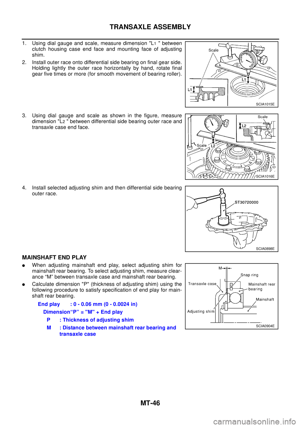
MT-46
TRANSAXLE ASSEMBLY
1. Using dial gauge and scale, measure dimension "L1" between
clutch housing case end face and mounting face of adjusting
shim.
2. Install outer race onto differential side bearing on final gear side.
Holding lightly the outer race horizontally by hand, rotate final
gear five times or more (for smooth movement of bearing roller).
3. Using dial gauge and scale as shown in the figure, measure
dimension "L
2" between differential side bearing outer race and
transaxle case end face.
4. Install selected adjusting shim and then differential side bearing
outer race.
MAINSHAFT END PLAY
lWhen adjusting mainshaft end play, select adjusting shim for
mainshaft rear bearing. To select adjusting shim, measure clear-
ance “M” between transaxle case and mainshaft rear bearing.
lCalculate dimension "P" (thickness of adjusting shim) using the
following procedure to satisfy specification of end play for main-
shaft rear bearing.
SCIA1015E
SCIA1016E
SCIA0898E
End play : 0 - 0.06 mm (0 - 0.0024 in)
Dimension“P” = "M" + End play
P : Thickness of adjusting shim
M : Distance between mainshaft rear bearing and
transaxle case
SCIA0904E
Page 2586 of 3066
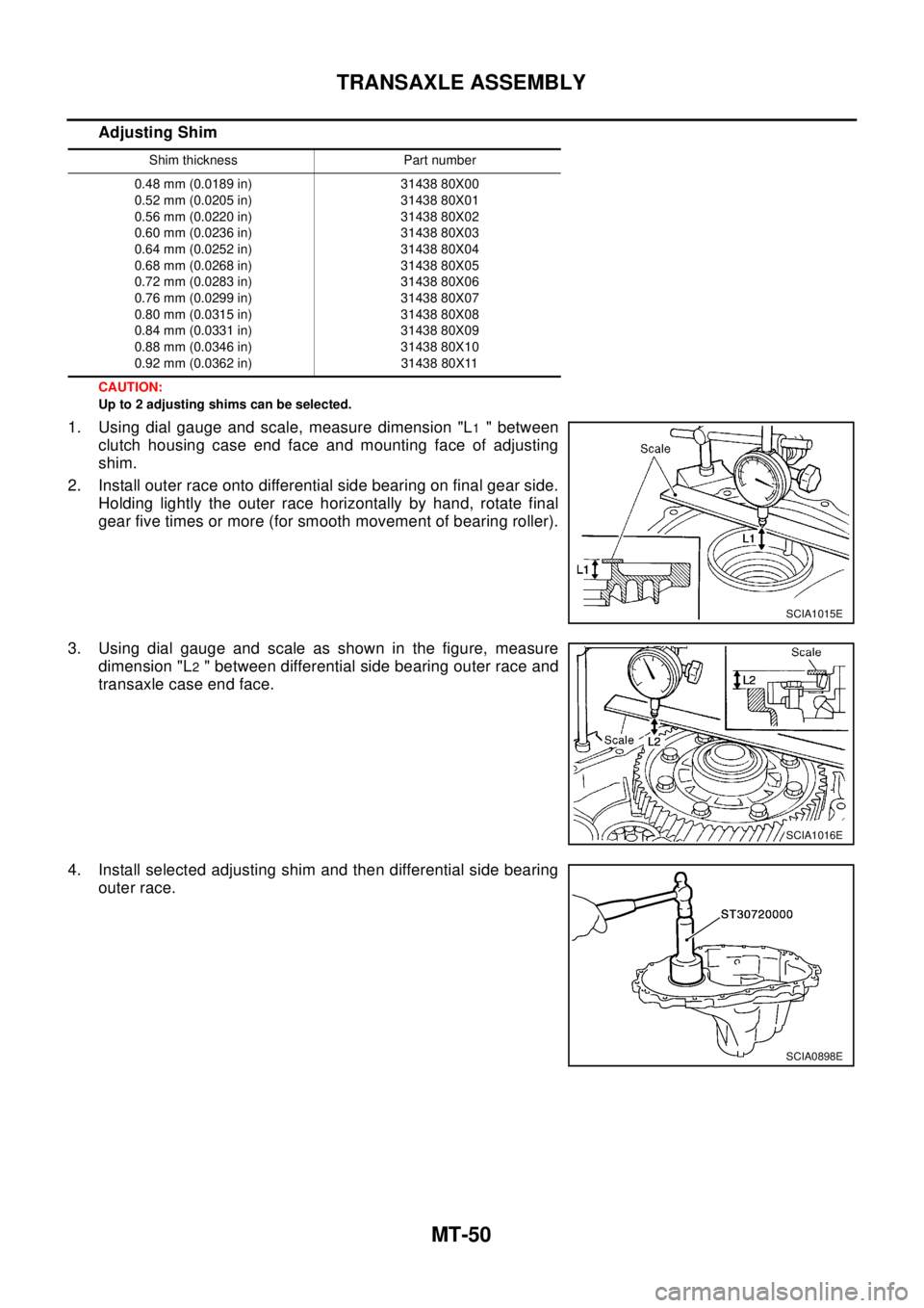
MT-50
TRANSAXLE ASSEMBLY
Adjusting Shim
CAUTION:
Up to 2 adjusting shims can be selected.
1. Using dial gauge and scale, measure dimension "L1" between
clutch housing case end face and mounting face of adjusting
shim.
2. Install outer race onto differential side bearing on final gear side.
Holding lightly the outer race horizontally by hand, rotate final
gear five times or more (for smooth movement of bearing roller).
3. Using dial gauge and scale as shown in the figure, measure
dimension "L
2" between differential side bearing outer race and
transaxle case end face.
4. Install selected adjusting shim and then differential side bearing
outer race.
Shim thickness Part number
0.48 mm (0.0189 in)
0.52 mm (0.0205 in)
0.56 mm (0.0220 in)
0.60 mm (0.0236 in)
0.64 mm (0.0252 in)
0.68 mm (0.0268 in)
0.72 mm (0.0283 in)
0.76 mm (0.0299 in)
0.80 mm (0.0315 in)
0.84 mm (0.0331 in)
0.88 mm (0.0346 in)
0.92 mm (0.0362 in)31438 80X00
31438 80X01
31438 80X02
31438 80X03
31438 80X04
31438 80X05
31438 80X06
31438 80X07
31438 80X08
31438 80X09
31438 80X10
31438 80X11
SCIA1015E
SCIA1016E
SCIA0898E