Page 743 of 3066

TIME CONTROL UNIT
BCS-5
C
D
E
F
G
H
I
J
L
MA
B
BCS
Time Control Unit Inspection TableEKS002ZW
Te r m i n a l
No.Wire
colorConnections Operation conditionVo l ta g e
(Approxi-
mate values)
1 L/B Power source (Fuse) — 12V
3 L/Y Super lock actuator Door key cylinder switchFree 0V
Unlocked 12V
4G/RPassenger and rear doors lock
actuatorDoor lock/unlock switchFree 0V
Unlocked 12V
6 Y/R Super lock actuator Door key cylinder switchFree 0V
Locked 12V
10 W Power source (C/B) — 12V
11 L Driver's door lock actuator Door lock/unlock switchFree 0V
Unlocked 12V
14 R/B Door lock actuator Door lock/unlock switchFree 0V
Locked 12V
16 B Ground — 0V
17 G Ignition switch (ON) — 12V
18 W/L Ignition key switch (Insert) Key inserted®key removed from IGN key cylinder 12V®0V
19 R/L Lighting switch 1ST, 2ND position: ON®OFF 12V®0V
20 GY Door lock/Unlock switch Neutral®Locks 5V®0V
23 PU Door lock/Unlock switch Neutral®Unlocks 5V®0V
24 OR/L Door key cylinder switch OFF (Neutral)®ON (Locked) 5V®0V
25 W/L Door key cylinder switch OFF (Neutral)®ON (Unlocked) 5V®0V
26 R/Y Interior room lampWhen interior room lamp is operated using remote control-
ler (Lamp switch is “DOOR” position)12V®0V
27 G/W Rear window defogger relay OFF®ON (Ignition key is in “ON” position) 12V®0V
28 Y/G Driver door unlock sensor Driver door: Locked®Unlocked 5V®0V
29 Y/L Passenger door unlock sensor Passenger door: Locked®Unlocked 5V®0V
30 R Doorswitchdriverside OFF(closed)®ON (open) 5V®0V
31 R/W Passenger and rear doors switch OFF (closed)®ON (open) 5V®0V
32 OR Multi-remote control unitRemote controller lock button is pushed.
(Ignition switch is not at “ON” position)0V®5V
33 P/L Multi-remote control unitRemote controller unlock button is pushed.
(Ignition switch is not at “ON” position)0V®5V
35 LG/B Rear window defogger switch OFF®ON 5V®0V
Page 755 of 3066
POWERDOORLOCKSYSTEM
BL-11
C
D
E
F
G
H
J
K
L
MA
B
BL
POWER DOOR LOCK SYSTEMPFP:24814
System DescriptionEIS001SE
OPERATION
Power door lock/unlock operation by door key cylinder
lWith the key inserted into driver's door key cylinder, turning it to LOCK will lock all doors.
lWith the key inserted into driver's door key cylinder, turning it to UNLOCK will unlock all doors.
Power door lock/unlock operation by lock/unlock switch
lWith lock/unlock switch setting to LOCK will lock all doors.
lWith lock/unlock switch setting to UNLOCK will unlock all doors.
Key reminder system
lIf the ignition key is in the ignition key cylinder and driver door is open, setting lock/unlock switch, lock
knob, key or multi-remote controller to “LOCK” locks the door once but then immediately unlocks all doors.
(signal from door unlock sensor driver side)
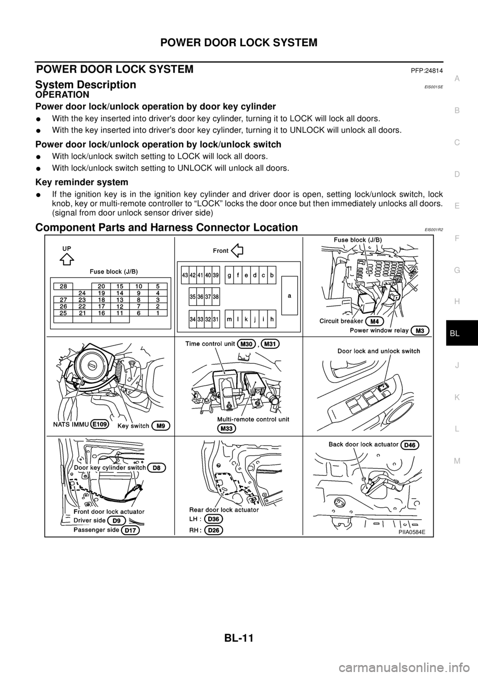
Component Parts and Harness Connector LocationEIS001R2
PIIA0584E
Page 757 of 3066
POWERDOORLOCKSYSTEM
BL-13
C
D
E
F
G
H
J
K
L
MA
B
BL
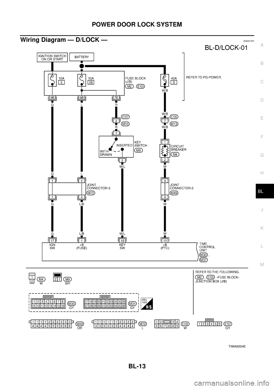
Wiring Diagram — D/LOCK —EIS001R4
TIWA0004E
Page 759 of 3066
POWERDOORLOCKSYSTEM
BL-15
C
D
E
F
G
H
J
K
L
MA
B
BL
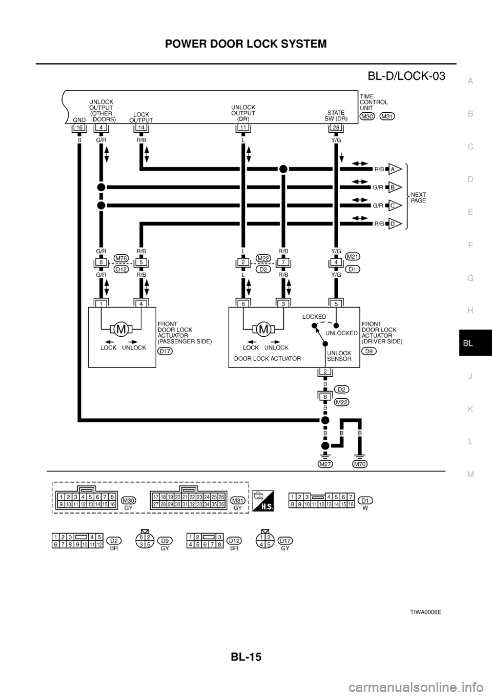
TIWA0006E
Page 761 of 3066
POWERDOORLOCKSYSTEM
BL-17
C
D
E
F
G
H
J
K
L
MA
B
BL
Terminal and Reference Value for Time Control UnitEIS000KP
Symptom ChartEIS001R5
*:Make sure the power door lock system operates properly.TER-
MINALWIRE
COLORITEM CONDITIONVOLTAGE
(Approximate values)
1 L/B BAT power supply — Battery voltage
4G/RPassenger door and rear door
(LH/RH) lock actuator lockPower door lock switch
Lock operation0V®12V
10 W Power source (C/B) — Battery voltage
11 L Driver door lock actuator lockPower door lock switch
Lock operation0V®12V
14 R/B All door lock actuator unlockPower door lock switch
Unlock operation0V®12V
16 B Ground — 0V
17 G IGN power supply — Battery voltage
18 W/L Key switchKey inserted (ON)®key removed
from IGN key cylinder (OFF)Battery voltage®0V
20 GYPower door lock switch lock sig-
nalLock operation (ON) 0V
Other than above (OFF) 5V
23 PUPower door lock switch unlock
signalUnlock operation (ON) 0V
Other than above (OFF) 5V
24 LG/R Door key cylinder lock switch OFF (Neutral)®ON (Locked) 5V®0V
25 OR/L Door key cylinder unlock switch OFF (Neutral)®ON (Unlocked) 5V®0V
28 Y/G Driver door lock switch signalUnlock (ON) 0V
Lock (OFF) 5V
30 R Driver door switch Door open (ON)®close (OFF) 0V®Battery voltage
Symptom Malfunctioning systemReference
page
Power door lock does not operate using any switchPower supply and ground circuit checkBL-18
Door lock actuator checkBL-20
If above systems are OK, replace time control unit. —
Power door lock does not operate with lock/unlock
switch.Door lock/unlock switch checkBL-18
If above system is OK, replace time control unit. —
Power door lock does not operate with door key cylin-
der switch.Door key cylinder switch checkBL-19
If above system is OK, replace time control unit. —
Specific door lock actuator does not operate.Door lock actuator checkBL-20
If above system is OK, replace time control unit. —
*Key reminder system does not operate.Door switch checkBL-21
Door unlock sensor checkBL-22
Key switch checkBL-23
If above system is OK, replace time control unit. —
Page 762 of 3066
BL-18
POWER DOOR LOCK SYSTEM
Power Supply and Ground Circuit Check
EIS001S7
1.CHECK POWER SUPPLY CIRCUIT
1. Turn ignition switch OFF.
2. Disconnect time control unit connector.
3. Check voltage between time control unit harness connector M30 terminal 1(L/B), 10(W) and body ground.
OK or NG?
OK >> GO TO 2
NG >> Check time control unit power supply circuit for open or
short.
2.CHECK GROUND CIRCUIT
Check continuity between time control unit harness connector M30 terminal 16(B) and body ground.
OK or NG?
OK >> Power supply and ground circuit is OK.
NG >> Check time control unit ground circuit for open or short.
Door Lock/Unlock Switch CheckEIS001S8
1.CHECKDOORLOCK/UNLOCKSWITCHSIGNAL
1. Disconnect time control unit harness connector.
2. Check continuity between time control unit harness connector M31 terminal 20(GY), 23(PU) and body
ground.
OK or NG?
OK >> Door lock/unlock switch is OK.
NG >> GO TO 2Te r m i n a l
Vo l ta g e
+–
1
Body
groundBattery voltage
10
SIIA1204E
: Continuity should exist.
SIIA1205E
Te r m i n a l sDoor lock/unlock
switchContinuity
20 – Body
groundLock Yes
Neutral or Unlock No
23 – Body
groundUnlock Yes
Neutral or Lock No
SIIA1206E
Page 763 of 3066
POWERDOORLOCKSYSTEM
BL-19
C
D
E
F
G
H
J
K
L
MA
B
BL
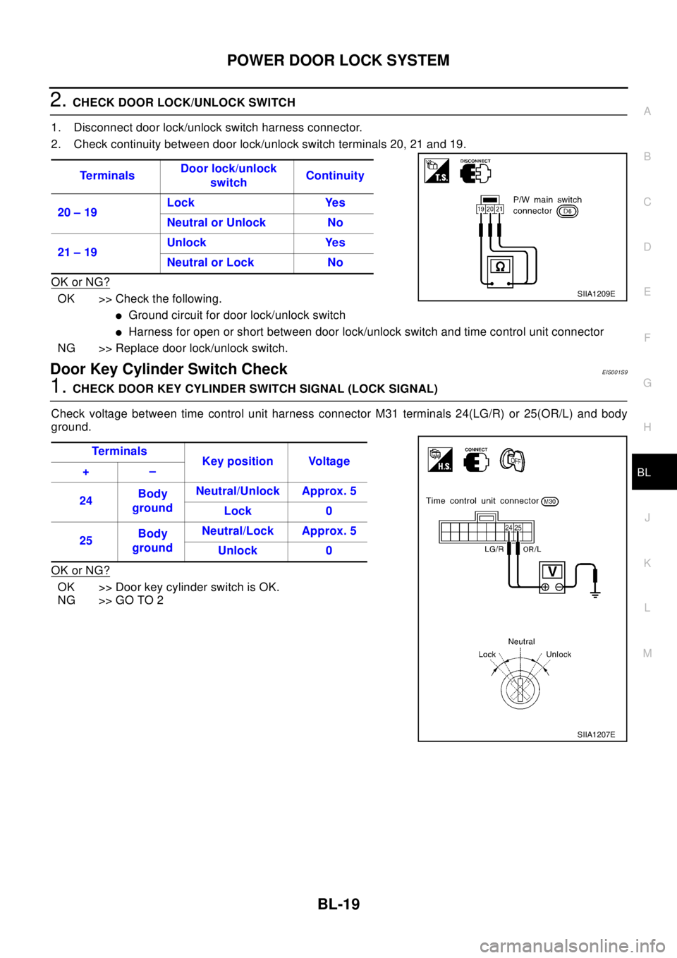
2.CHECK DOOR LOCK/UNLOCK SWITCH
1. Disconnect door lock/unlock switch harness connector.
2. Check continuity between door lock/unlock switch terminals 20, 21 and 19.
OK or NG?
OK >> Check the following.
lGround circuit for door lock/unlock switch
lHarness for open or short between door lock/unlock switch and time control unit connector
NG >> Replace door lock/unlock switch.
Door Key Cylinder Switch CheckEIS001S9
1.CHECK DOOR KEY CYLINDER SWITCH SIGNAL (LOCK SIGNAL)
Check voltage between time control unit harness connector M31 terminals 24(LG/R) or 25(OR/L) and body
ground.
OK or NG?
OK >> Door key cylinder switch is OK.
NG >> GO TO 2Te r m i n a l sDoor lock/unlock
switchContinuity
20 – 19Lock Yes
Neutral or Unlock No
21 – 19Unlock Yes
Neutral or Lock No
SIIA1209E
Te r m i na l s
Key position Voltage
+–
24Body
groundNeutral/Unlock Approx. 5
Lock 0
25Body
groundNeutral/Lock Approx. 5
Unlock 0
SIIA1207E
Page 765 of 3066
POWERDOORLOCKSYSTEM
BL-21
C
D
E
F
G
H
J
K
L
MA
B
BL
2.CHECK DOOR LOCK ACTUATOR
1. Disconnect door lock actuator harness connector.
2. Apply 12V direct current to door lock actuator and check opera-
tion.
( ): Passenger and rear LH door lock actuator.
OK or NG?
OK >> Check harness for open or short between time control
unit connector and door lock actuator.
NG >> Replace door lock actuator.
Door Switch CheckEIS001SB
1.CHECK DOOR SWITCH INPUT SIGNAL
1. Turn ignition switch OFF.
2. Check voltage between time control unit harness connector M31 terminal 30(R) and body ground.
OK or NG?
OK >> Door switch is OK.
NG >> GO TO 2Te r m i n a l s
Door lock actuator operation
3 (4) 6 (1)
+ – Locked®Unlocked
– + Unlocked®Locked
SIIA1213E
Terminal Driver's door Voltage
30–BodygroundClosed Approx. 5
Open 0
SIIA1214E