2003 NISSAN X-TRAIL sensor
[x] Cancel search: sensorPage 2199 of 3066
PREPARATION
FAX-3
C
E
F
G
H
I
J
K
L
MA
B
FA X
PREPARATIONPFP:00002
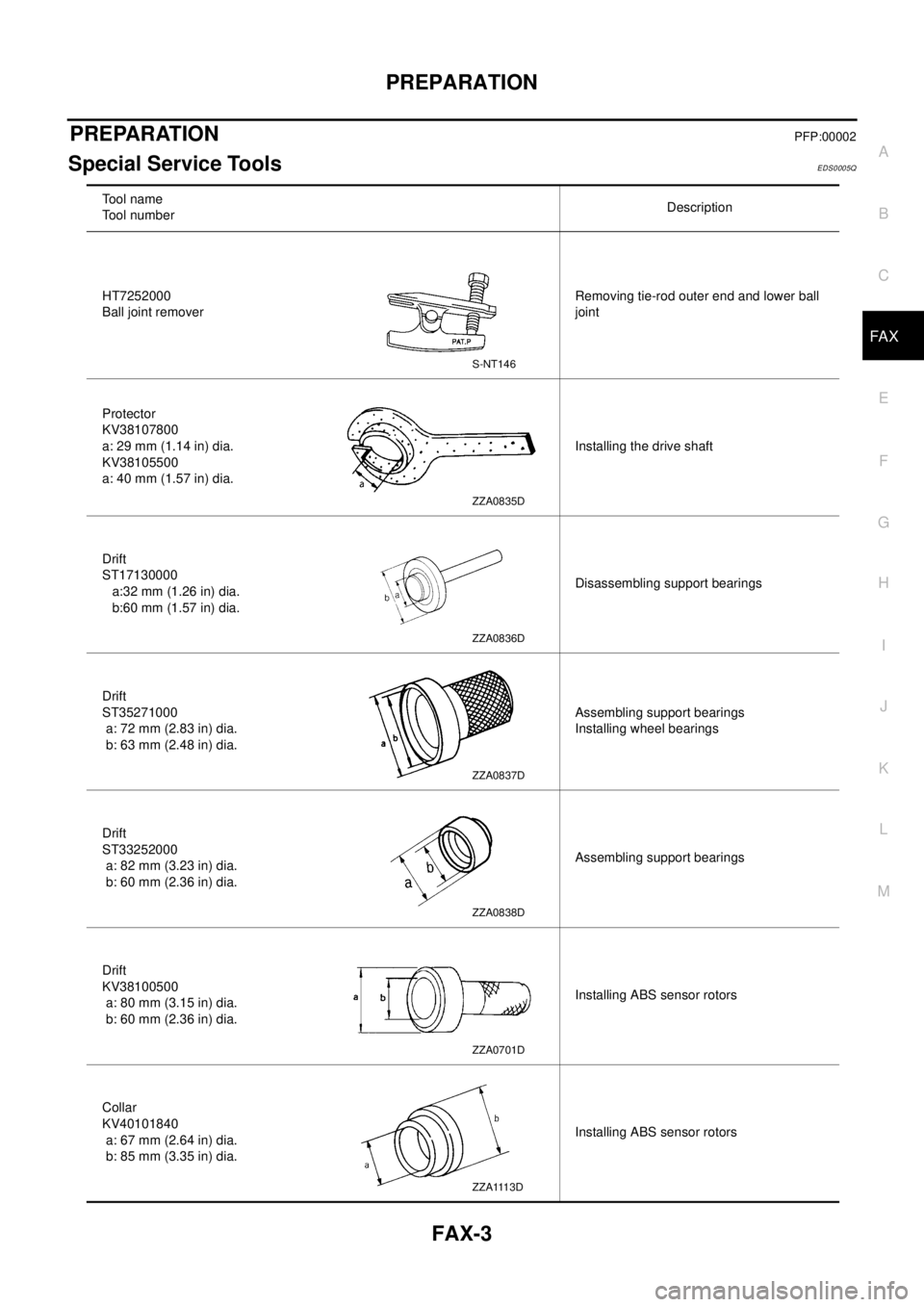
Special Service ToolsEDS0005Q
To o l n a m e
Tool numberDescription
HT7252000
Ball joint removerRemoving tie-rod outer end and lower ball
joint
Protector
KV38107800
a: 29 mm (1.14 in) dia.
KV38105500
a: 40 mm (1.57 in) dia.Installing the drive shaft
Drift
ST17130000
a:32 mm (1.26 in) dia.
b:60 mm (1.57 in) dia.Disassembling support bearings
Drift
ST35271000
a: 72 mm (2.83 in) dia.
b: 63 mm (2.48 in) dia.Assembling support bearings
Installing wheel bearings
Drift
ST33252000
a: 82 mm (3.23 in) dia.
b: 60 mm (2.36 in) dia.Assembling support bearings
Drift
KV38100500
a: 80 mm (3.15 in) dia.
b: 60 mm (2.36 in) dia.Installing ABS sensor rotors
Collar
KV40101840
a: 67 mm (2.64 in) dia.
b: 85 mm (3.35 in) dia.Installing ABS sensor rotors
S-NT146
ZZA0835D
ZZA0836D
ZZA0837D
ZZA0838D
ZZA0701D
ZZA1113D
Page 2203 of 3066
FRONT WHEEL HUB AND KNUCKLE
FAX-7
C
E
F
G
H
I
J
K
L
MA
B
FA X
FRONT WHEEL HUB AND KNUCKLEPFP:40202
On-Vehicle InspectionEDS0005R
Inspect to check that there is no excessive play, cracking, wear, or
other damage to front axle.
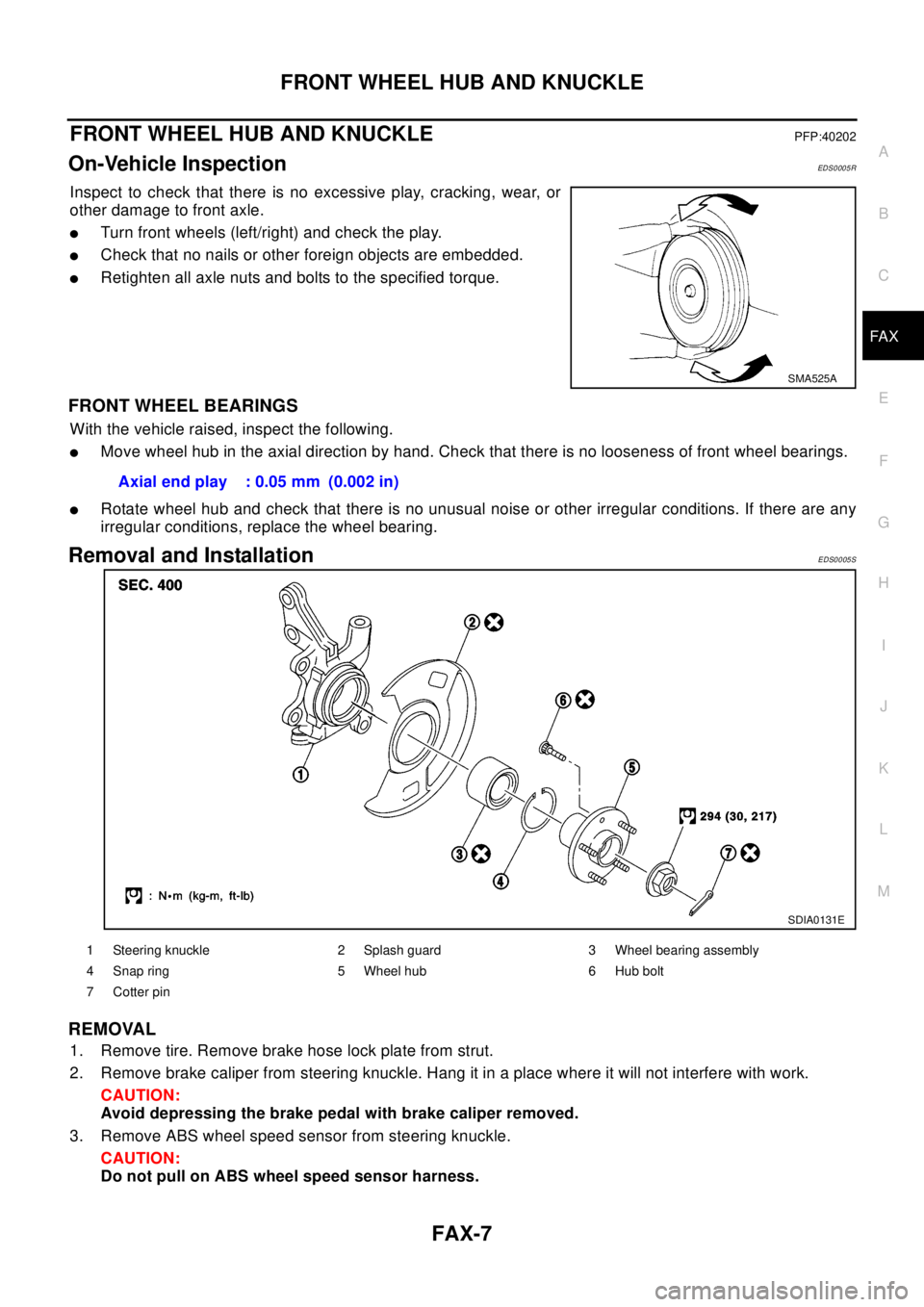
lTurn front wheels (left/right) and check the play.
lCheck that no nails or other foreign objects are embedded.
lRetighten all axle nuts and bolts to the specified torque.
FRONT WHEEL BEARINGS
With the vehicle raised, inspect the following.
lMove wheel hub in the axial direction by hand. Check that there is no looseness of front wheel bearings.
lRotate wheel hub and check that there is no unusual noise or other irregular conditions. If there are any
irregular conditions, replace the wheel bearing.
Removal and InstallationEDS0005S
REMOVAL
1. Remove tire. Remove brake hose lock plate from strut.
2. Remove brake caliper from steering knuckle. Hang it in a place where it will not interfere with work.
CAUTION:
Avoid depressing the brake pedal with brake caliper removed.
3. Remove ABS wheel speed sensor from steering knuckle.
CAUTION:
Do not pull on ABS wheel speed sensor harness.
SMA525A
Axial end play : 0.05 mm (0.002 in)
SDIA0131E
1 Steering knuckle 2 Splash guard 3 Wheel bearing assembly
4 Snap ring 5 Wheel hub 6 Hub bolt
7Cotterpin
Page 2207 of 3066
FRONT DRIVE SHAFT
FAX-11
C
E
F
G
H
I
J
K
L
MA
B
FA X
FRONT DRIVE SHAFTPFP:39100
Removal and InstallationEDS0005U
REMOVAL
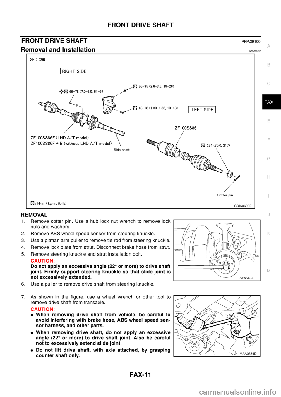
1. Remove cotter pin. Use a hub lock nut wrench to remove lock
nuts and washers.
2. Remove ABS wheel speed sensor from steering knuckle.
3. Use a pitman arm puller to remove tie rod from steering knuckle.
4. Remove lock plate from strut. Disconnect brake hose from strut.
5. Remove steering knuckle and strut installation bolt.
CAUTION:
Do not apply an excessive angle (22°or more) to drive shaft
joint. Firmly support steering knuckle so that slide joint is
not excessively extended.
6. Use a puller to remove drive shaft from steering knuckle.
7. As shown in the figure, use a wheel wrench or other tool to
remove drive shaft from transaxle.
CAUTION:
lWhen removing drive shaft from vehicle, be careful to
avoid interfering with brake hose, ABS wheel speed sen-
sor harness, and other parts.
lWhen removing drive shaft, do not apply an excessive
angle (22°or more) to drive shaft joint. Also be careful
not to excessively extend slide joint.
lDo not lift drive shaft, with axle attached, by grasping
counter shaft only.
SDIA0609E
SFA649A
MAA0384D
Page 2208 of 3066
FAX-12
FRONT DRIVE SHAFT
lDo not allow drive shaft, with transaxle inserted, to hang down without support for counter
shaft, wheel joints, and other parts.
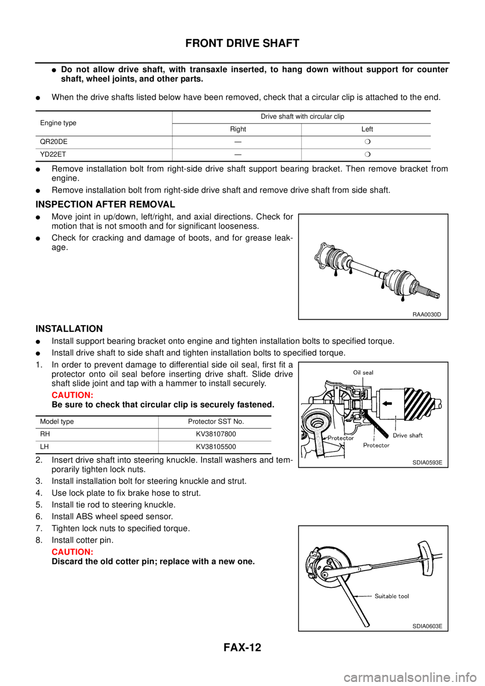
lWhen the drive shafts listed below have been removed, check that a circular clip is attached to the end.
lRemove installation bolt from right-side drive shaft support bearing bracket. Then remove bracket from
engine.
lRemove installation bolt from right-side drive shaft and remove drive shaft from side shaft.
INSPECTION AFTER REMOVAL
lMove joint in up/down, left/right, and axial directions. Check for
motion that is not smooth and for significant looseness.
lCheck for cracking and damage of boots, and for grease leak-
age.
INSTALLATION
lInstall support bearing bracket onto engine and tighten installation bolts to specified torque.
lInstall drive shaft to side shaft and tighten installation bolts to specified torque.
1. In order to prevent damage to differential side oil seal, first fit a
protector onto oil seal before inserting drive shaft. Slide drive
shaft slide joint and tap with a hammer to install securely.
CAUTION:
Be sure to check that circular clip is securely fastened.
2. Insert drive shaft into steering knuckle. Install washers and tem-
porarily tighten lock nuts.
3. Install installation bolt for steering knuckle and strut.
4. Use lock plate to fix brake hose to strut.
5. Install tie rod to steering knuckle.
6. Install ABS wheel speed sensor.
7. Tighten lock nuts to specified torque.
8. Install cotter pin.
CAUTION:
Discard the old cotter pin; replace with a new one.
Engine typeDrive shaft with circular clip
Right Left
QR20DE —m
YD22ET —m
RAA0030D
Model type Protector SST No.
RH KV38107800
LH KV38105500
SDIA0593E
SDIA0603E
Page 2210 of 3066
FAX-14
FRONT DRIVE SHAFT
Wheel Side
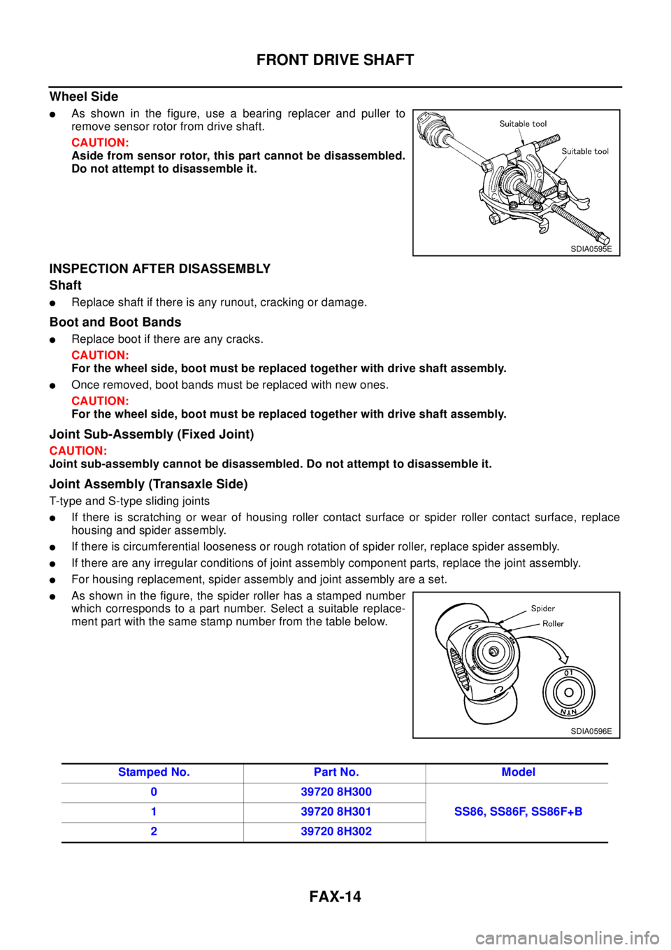
lAs shown in the figure, use a bearing replacer and puller to
remove sensor rotor from drive shaft.
CAUTION:
Aside from sensor rotor, this part cannot be disassembled.
Do not attempt to disassemble it.
INSPECTION AFTER DISASSEMBLY
Shaft
lReplace shaft if there is any runout, cracking or damage.
Boot and Boot Bands
lReplace boot if there are any cracks.
CAUTION:
For the wheel side, boot must be replaced together with drive shaft assembly.
lOnce removed, boot bands must be replaced with new ones.
CAUTION:
For the wheel side, boot must be replaced together with drive shaft assembly.
Joint Sub-Assembly (Fixed Joint)
CAUTION:
Joint sub-assembly cannot be disassembled. Do not attempt to disassemble it.
Joint Assembly (Transaxle Side)
T-typeandS-typeslidingjoints
lIf there is scratching or wear of housing roller contact surface or spider roller contact surface, replace
housing and spider assembly.
lIf there is circumferential looseness or rough rotation of spider roller, replace spider assembly.
lIf there are any irregular conditions of joint assembly component parts, replace the joint assembly.
lFor housing replacement, spider assembly and joint assembly are a set.
lAs shown in the figure, the spider roller has a stamped number
which corresponds to a part number. Select a suitable replace-
ment part with the same stamp number from the table below.
SDIA0595E
SDIA0596E
Stamped No. Part No. Model
0 39720 8H300
SS86, SS86F, SS86F+B 1 39720 8H301
2 39720 8H302
Page 2212 of 3066
FAX-16
FRONT DRIVE SHAFT
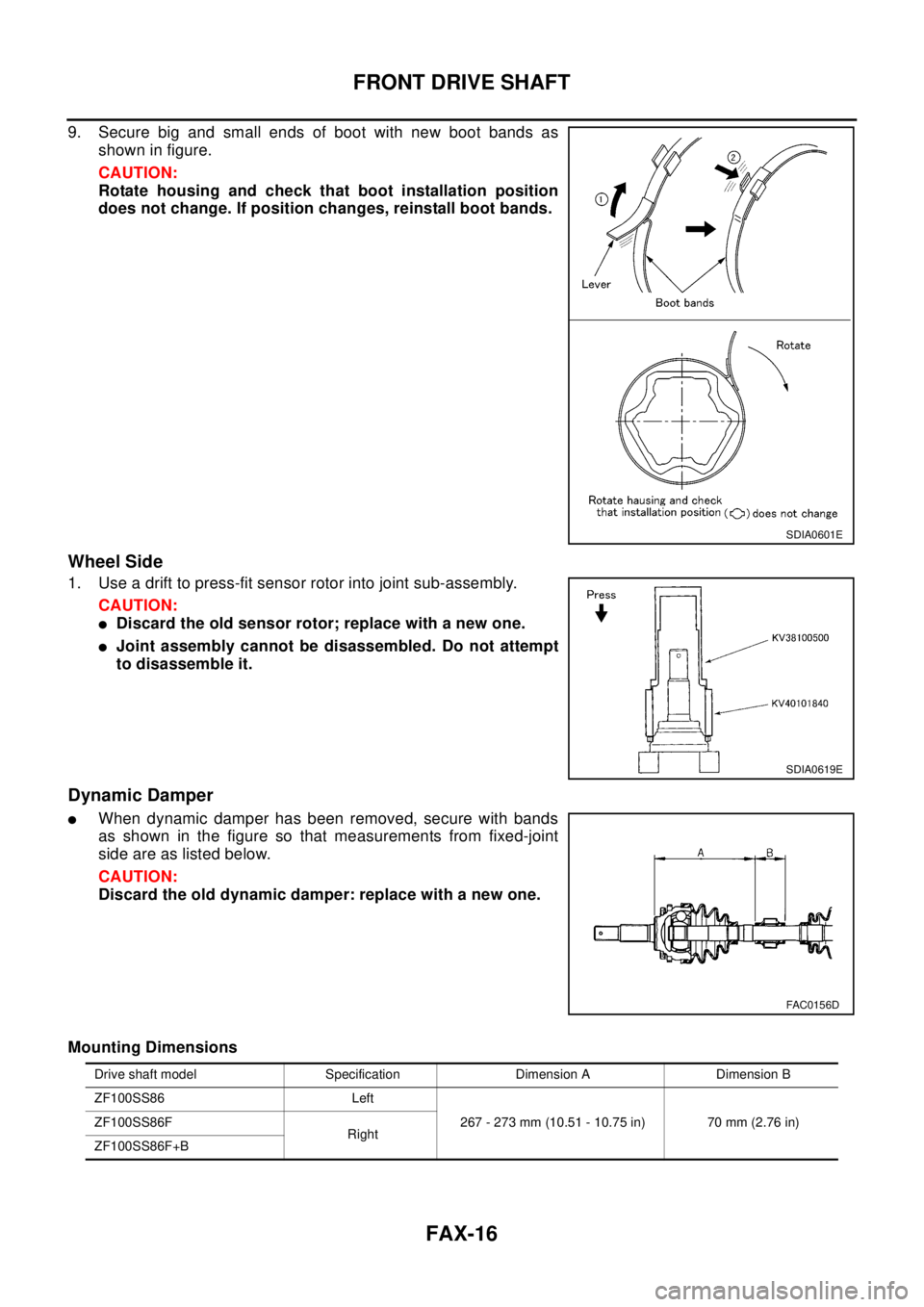
9. Secure big and small ends of boot with new boot bands as
shown in figure.
CAUTION:
Rotate housing and check that boot installation position
does not change. If position changes, reinstall boot bands.
Wheel Side
1. Use a drift to press-fit sensor rotor into joint sub-assembly.
CAUTION:
lDiscard the old sensor rotor; replace with a new one.
lJoint assembly cannot be disassembled. Do not attempt
to disassemble it.
Dynamic Damper
lWhen dynamic damper has been removed, secure with bands
as shown in the figure so that measurements from fixed-joint
side are as listed below.
CAUTION:
Discard the old dynamic damper: replace with a new one.
Mounting Dimensions
SDIA0601E
SDIA0619E
FAC0156D
Drive shaft model Specification Dimension A Dimension B
ZF100SS86 Left
267 - 273 mm (10.51 - 10.75 in) 70 mm (2.76 in) ZF100SS86F
Right
ZF100SS86F+B
Page 2216 of 3066
FL-1
FUEL SYSTEM
B ENGINE
CONTENTS
C
D
E
F
G
H
I
J
K
L
M
SECTION
A
FL
FUEL SYSTEM
QR20DE
PREPARATION ........................................................... 2
Commercial Service Tool ......................................... 2
FUEL SYSTEM ........................................................... 3
Checking Fuel Lines ................................................. 3
General Precautions ................................................ 3
FUEL LEVEL SENSOR UNIT, FUEL FILTER AND
FUEL PUMP ASSEMBLY ........................................... 4
Removal and Installation .......................................... 4
REMOVAL ............................................................. 4
INSPECTION AFTER REMOVAL ......................... 6
INSTALLATION ..................................................... 6
INSPECTION AFTER INSTALLATION ................. 7
Disassembly and Assembly ..................................... 7
DISASSEMBLY ..................................................... 7
ASSEMBLY ........................................................... 8
FUEL TANK ................................................................ 9
Removal and Installation .......................................... 9
REMOVAL ............................................................. 9
INSTALLATION ................................................... 10
Inspection After Installation .....................................11
SERVICE DATA AND SPECIFICATIONS (SDS) ...... 12
Standard and Limit ................................................. 12
Tightening Torque ................................................... 12
YD22DDTi
PREPARATION ......................................................... 13
Commercial Service Tool ........................................ 13
FUEL SYSTEM ......................................................... 14
Checking Fuel Lines ............................................... 14
General Precautions ............................................... 14
FUEL FILTER ............................................................ 15
Removal and Installation ........................................ 15
REMOVAL ........................................................... 15
INSTALLATION ................................................... 15
INSPECTION AFTER INSTALLATION ................ 15
Air Bleeding ............................................................ 16
Draining Water ........................................................ 16
FUEL LEVEL SENSOR UNIT ................................... 17
Removal and Installation ........................................ 17
REMOVAL ........................................................... 17
INSPECTION AFTER REMOVAL ....................... 19
INSTALLATION ................................................... 19
INSPECTION AFTER INSTALLATION ................ 20
FUEL TANK .............................................................. 21
Removal and Installation ........................................ 21
REMOVAL ........................................................... 21
INSTALLATION ................................................... 22
Inspection After Installation .................................... 22
SERVICE DATA AND SPECIFICATIONS (SDS) ...... 23
Standard and Limit .................................................. 23
Tightening Torque ................................................... 23
Page 2219 of 3066
![NISSAN X-TRAIL 2003 Electronic Repair Manual FL-4
[QR20DE]
FUEL LEVEL SENSOR UNIT, FUEL FILTER AND FUEL PUMP ASSEMBLY
FUEL LEVEL SENSOR UNIT, FUEL FILTER AND FUEL PUMP ASSEMBLY
PFP:17042
Removal and InstallationEBS00BKR
REMOVAL
WAR NIN G:
Be sur NISSAN X-TRAIL 2003 Electronic Repair Manual FL-4
[QR20DE]
FUEL LEVEL SENSOR UNIT, FUEL FILTER AND FUEL PUMP ASSEMBLY
FUEL LEVEL SENSOR UNIT, FUEL FILTER AND FUEL PUMP ASSEMBLY
PFP:17042
Removal and InstallationEBS00BKR
REMOVAL
WAR NIN G:
Be sur](/manual-img/5/57402/w960_57402-2218.png)
FL-4
[QR20DE]
FUEL LEVEL SENSOR UNIT, FUEL FILTER AND FUEL PUMP ASSEMBLY
FUEL LEVEL SENSOR UNIT, FUEL FILTER AND FUEL PUMP ASSEMBLY
PFP:17042
Removal and InstallationEBS00BKR
REMOVAL
WAR NIN G:
Be sure to read “General Precautions” when working on fuel system. Refer toFL-3, "
General Precau-
tions"
1. Release fuel pressure from fuel line.
Refer toEC-34, "
FUEL PRESSURE RELEASE"(WITH EURO-
OBD),EC-399, "
FUEL PRESSURE RELEASE"(WITHOUT
EURO-OBD).
2. Open fuel filer lid.
3. Open the filler cap and release the pressure inside the fuel tank.
4. Check fuel level on level place. If gauge indicates more than the
level shown in figure (full or almost full), drain fuel from fuel tank
until gauge indicates level shown in figure or below.
In case of fuel pump does not operate, take following procedure.
a. Insert fuel tube of less than 25 mm (0.98 in) in diameter into fuel
filler tube through fuel filler opening to draw fuel from fuel filler
tube.
b. Disconnect fuel filler hose from fuel filler tube.
c. Insert fuel tube into fuel tank through fuel filler hose to draw fuel
from fuel tank.
lAs a guide, fuel level becomes the position shown in figure or
below when approximately 15 liter (13-1/4 lmp qt) of fuel are drained from fuel position.
KBIA0278E
1Lockring 2Main fuel level sensor unit, fuel filter
and fuel pump assembly3Jet pump, fuel hose and jet pump inlet
assembly
4 Chamber 5 Seal packing 6 Sub fuel level sensor unit
KBIA0280E
FEL0403D