2003 NISSAN X-TRAIL sensor
[x] Cancel search: sensorPage 2234 of 3066
![NISSAN X-TRAIL 2003 Electronic Repair Manual FUEL LEVEL SENSOR UNIT
FL-19
[YD22DDTi]
C
D
E
F
G
H
I
J
K
L
MA
FL
lTo keep clean the connecting portion and to avoid damage
and foreign materials, cover them completely with plastic
bags or something NISSAN X-TRAIL 2003 Electronic Repair Manual FUEL LEVEL SENSOR UNIT
FL-19
[YD22DDTi]
C
D
E
F
G
H
I
J
K
L
MA
FL
lTo keep clean the connecting portion and to avoid damage
and foreign materials, cover them completely with plastic
bags or something](/manual-img/5/57402/w960_57402-2233.png)
FUEL LEVEL SENSOR UNIT
FL-19
[YD22DDTi]
C
D
E
F
G
H
I
J
K
L
MA
FL
lTo keep clean the connecting portion and to avoid damage
and foreign materials, cover them completely with plastic
bags or something similar.
8. Using a lock ring wrench, remove the lock ring.
9. Remove main fuel level sensor unit and sub fuel level sensor
unit.
CAUTION:
lDo not bend the float arm during removal.
lAvoid impacts such as falling when handling components.
Removal of main fuel level sensor unit:
lRaise the fuel level sensor unit, and remove the jet pump.
lLeave the jet pump on the fuel tank with the fuel hose.
lIf necessary, remove the chamber from the bottom of the fuel
tank.
lRemove the chamber by sliding toward the rear of the vehicle.
Removal of sub fuel level sensor unit:
lRaise and release the sub fuel level sensor unit to remove.
lIf necessary, remove the jet pump inlet from the bottom of the fuel tank.
To remove it, pinch the tabs (2 places).
INSPECTION AFTER REMOVAL
Make sure the fuel pump strainer is free from foreign materials, If any are found, remove them.
INSTALLATION
Install in the reverse order of removal paying attention to the follow-
ing.
lWhen installing the chamber and jet pump, insert them fully until
a click sound of full stopper engagement is heard (for jet pump
inlet).
lConnect the quick connector as follows.
1. Check the connection for damage and foreign materials.
2. Align the connector with the tube, then insert the connector
straight into the tube until a click is heard.
3. After connecting, make sure that the connection is secure by fol-
lowing the steps below.
PBIC0163E
PBIC0240E
SBIA0142E
SBIA0143E
Page 2235 of 3066
![NISSAN X-TRAIL 2003 Electronic Repair Manual FL-20
[YD22DDTi]
FUEL LEVEL SENSOR UNIT
lVisually confirm that the two retainer tabs are connected to the connector.
lPull the tube and the connector to make sure they are securely connected.
lInstall NISSAN X-TRAIL 2003 Electronic Repair Manual FL-20
[YD22DDTi]
FUEL LEVEL SENSOR UNIT
lVisually confirm that the two retainer tabs are connected to the connector.
lPull the tube and the connector to make sure they are securely connected.
lInstall](/manual-img/5/57402/w960_57402-2234.png)
FL-20
[YD22DDTi]
FUEL LEVEL SENSOR UNIT
lVisually confirm that the two retainer tabs are connected to the connector.
lPull the tube and the connector to make sure they are securely connected.
lInstall fuel level sensor unit with mating mark (triangular protrusion) facing between two carved lines on
fuel tank. (Figure shows left side of fuel tank.)
NOTE:
On right side of fuel tank, there are three carved lines on fuel tank. Set mating mark between two outer
carved lines.
lInstall the inspection hole cover with the front mark (arrow) fac-
ing front of the vehicle (Both for RH and LH).
INSPECTION AFTER INSTALLATION
lStart the engine and rev it up, and make sure there is no fuel leakage at connections.
SBIA0144E
Page 2237 of 3066
![NISSAN X-TRAIL 2003 Electronic Repair Manual FL-22
[YD22DDTi]
FUEL TANK
10. Using a transmission jack, support the bottom of the rear final
drive.
11. Remove the mounting nuts on the rear suspension member, and
lower the transmission jack carefu NISSAN X-TRAIL 2003 Electronic Repair Manual FL-22
[YD22DDTi]
FUEL TANK
10. Using a transmission jack, support the bottom of the rear final
drive.
11. Remove the mounting nuts on the rear suspension member, and
lower the transmission jack carefu](/manual-img/5/57402/w960_57402-2236.png)
FL-22
[YD22DDTi]
FUEL TANK
10. Using a transmission jack, support the bottom of the rear final
drive.
11. Remove the mounting nuts on the rear suspension member, and
lower the transmission jack carefully until just before the rear
suspension member is removed from the stud bolts on the vehi-
cle.
12. Disconnect fuel filler hose, EVAP hose and vent hose at fuel
tank side.
For disconnection procedure of the quick connector. Refer to
FL-17, "
FUEL LEVEL SENSOR UNIT".
13. Remove fuel tank protector.
14. Remove fuel tank band mounting bolts while supporting fuel
tank.
15. Remove fuel tank.
INSTALLATION
lInstall in the reverse order of removal paying attention to the following.
lSurely clamp fuel hoses and insert hose to the length below.
lBe sure hose clamp is not positioned on swelled area of fuel tube.
lTighten fuel hose clamp so that the distance between its lugs becomes to the following.
lPush the mounting band pin to the vehicle side securely.
lBefore fixing the fuel tank, temporarily install the fuel filler tube.
CAUTION:
Use genuine fuel filler tube mounting bolts or equivalent. Make sure to tighten them to the speci-
fied torque.
lTo connect the quick connector. Refer toFL-17, "FUEL LEVEL SENSOR UNIT".
Inspection After InstallationEBS00BL4
Run engine and check for fuel leaks at connections.
KBIA0285E
KBIA0286E
KBIA0290E
Fuel filler hose : 35 mm (1.38 in)
The other hose : 25 mm (0.98 in)
Fuel tank side : 5 - 9 mm (0.20 - 0.35 in)
Fuel filler tube side : 7 - 11 mm (0.28 - 0.43 in)
Page 2247 of 3066

FSU-8
COIL SPRING AND SHOCK ABSORBER
COIL SPRING AND SHOCK ABSORBER
PFP:54302
Removal and InstallationEES00074
REMOVAL
1. Remove tires. Remove brake caliper and hung it aside.
CAUTION:
Avoid depressing brake pedal with brake caliper removed.
2. Remove electrical wires of ABS wheel speed sensor from strut.
3. Remove brake hose lock plate.
4. Remove mounting bolts and nuts securing steering knuckle to strut.
5. Remove mounting nuts on top of strut and remove upper mounting plate and strut from vehicle.
INSTALLATION
lRefer toFSU-5, "Components"in “Front Suspension Assembly” for tightening torque. Tighten in the
reverse order of removal.
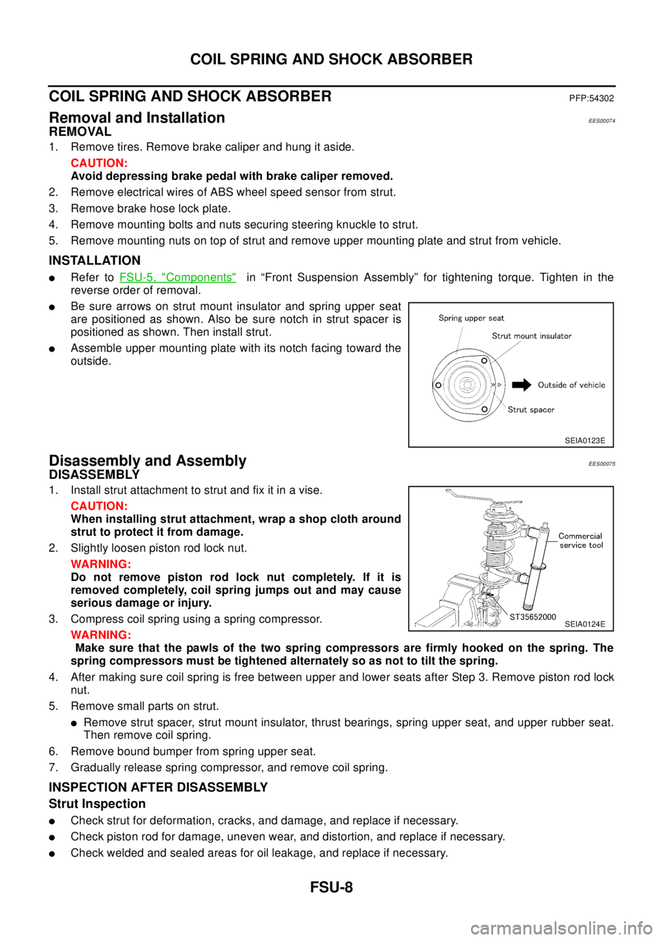
lBe sure arrows on strut mount insulator and spring upper seat
are positioned as shown. Also be sure notch in strut spacer is
positioned as shown. Then install strut.
lAssemble upper mounting plate with its notch facing toward the
outside.
Disassembly and AssemblyEES00075
DISASSEMBLY
1. Install strut attachment to strut and fix it in a vise.
CAUTION:
When installing strut attachment, wrap a shop cloth around
strut to protect it from damage.
2. Slightly loosen piston rod lock nut.
WAR NIN G:
Do not remove piston rod lock nut completely. If it is
removed completely, coil spring jumps out and may cause
serious damage or injury.
3. Compress coil spring using a spring compressor.
WAR NIN G:
Make sure that the pawls of the two spring compressors are firmly hooked on the spring. The
spring compressors must be tightened alternately so as not to tilt the spring.
4. After making sure coil spring is free between upper and lower seats after Step 3. Remove piston rod lock
nut.
5. Remove small parts on strut.
lRemove strut spacer, strut mount insulator, thrust bearings, spring upper seat, and upper rubber seat.
Then remove coil spring.
6. Remove bound bumper from spring upper seat.
7. Gradually release spring compressor, and remove coil spring.
INSPECTION AFTER DISASSEMBLY
Strut Inspection
lCheck strut for deformation, cracks, and damage, and replace if necessary.
lCheck piston rod for damage, uneven wear, and distortion, and replace if necessary.
lCheck welded and sealed areas for oil leakage, and replace if necessary.
SEIA0123E
SEIA0124E
Page 2259 of 3066

GI-6
PRECAUTIONS
Precautions for Multiport Fuel Injection System or Engine Control System
EAS000FT
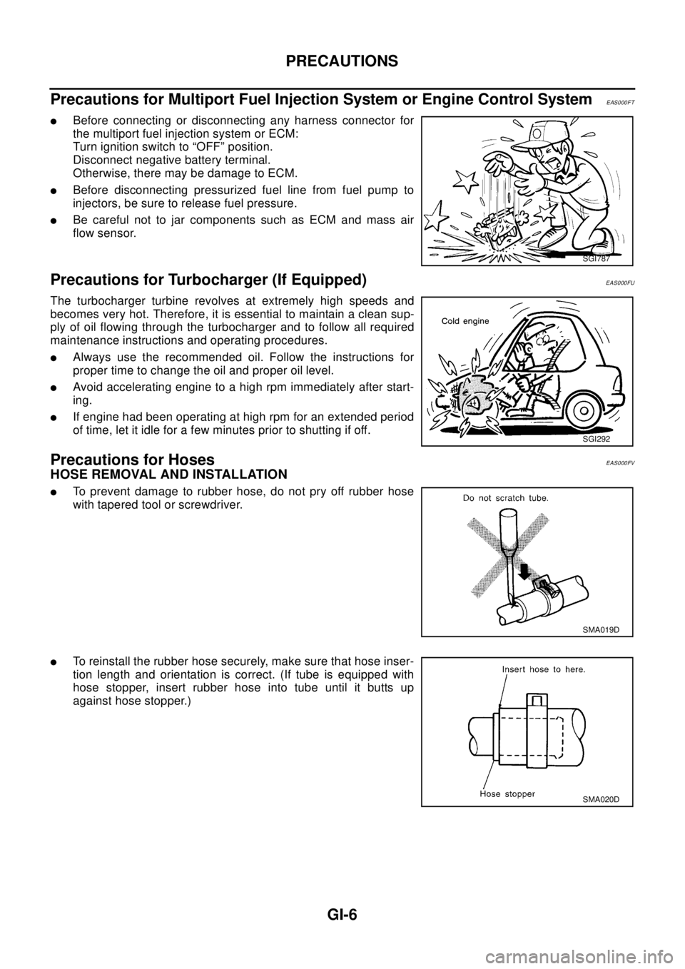
lBefore connecting or disconnecting any harness connector for
the multiport fuel injection system or ECM:
Turn ignition switch to “OFF” position.
Disconnect negative battery terminal.
Otherwise, there may be damage to ECM.
lBefore disconnecting pressurized fuel line from fuel pump to
injectors, be sure to release fuel pressure.
lBe careful not to jar components such as ECM and mass air
flow sensor.
Precautions for Turbocharger (If Equipped)EAS000FU
The turbocharger turbine revolves at extremely high speeds and
becomes very hot. Therefore, it is essential to maintain a clean sup-
ply of oil flowing through the turbocharger and to follow all required
maintenance instructions and operating procedures.
lAlways use the recommended oil. Follow the instructions for
proper time to change the oil and proper oil level.
lAvoid accelerating engine to a high rpm immediately after start-
ing.
lIf engine had been operating at high rpm for an extended period
of time, let it idle for a few minutes prior to shutting if off.
Precautions for HosesEAS000FV
HOSE REMOVAL AND INSTALLATION
lTo prevent damage to rubber hose, do not pry off rubber hose
with tapered tool or screwdriver.
lTo reinstall the rubber hose securely, make sure that hose inser-
tion length and orientation is correct. (If tube is equipped with
hose stopper, insert rubber hose into tube until it butts up
against hose stopper.)
SGI787
SGI292
SMA019D
SMA020D
Page 2278 of 3066

SERVICE INFORMATION FOR ELECTRICAL INCIDENT
GI-25
lVehicle vibration
lHeat sensitive
lFreezing
lWater intrusion
lElectrical load
lCold or hot start up
Get a thorough description of the incident from the customer. It is important for simulating the conditions of the
problem.
Vehicle Vibratio n
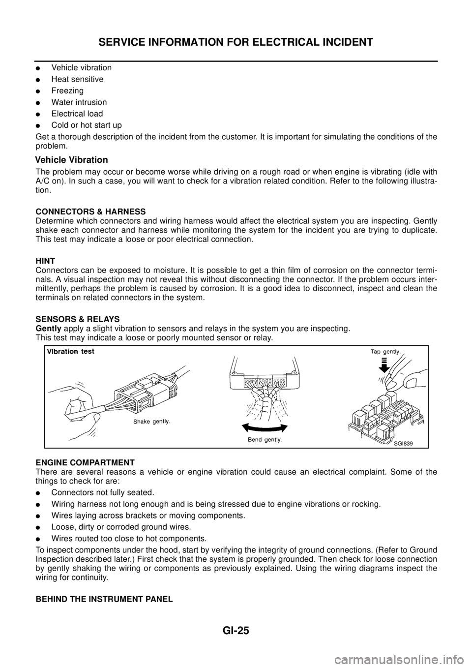
The problem may occur or become worse while driving on a rough road or when engine is vibrating (idle with
A/C on). In such a case, you will want to check for a vibration related condition. Refer to the following illustra-
tion.
CONNECTORS & HARNESS
Determine which connectors and wiring harness would affect the electrical system you are inspecting. Gently
shake each connector and harness while monitoring the system for the incident you are trying to duplicate.
This test may indicate a loose or poor electrical connection.
HINT
Connectors can be exposed to moisture. It is possible to get a thin film of corrosion on the connector termi-
nals. A visual inspection may not reveal this without disconnecting the connector. If the problem occurs inter-
mittently, perhaps the problem is caused by corrosion. It is a good idea to disconnect, inspect and clean the
terminals on related connectors in the system.
SENSORS & RELAYS
Gentlyapply a slight vibration to sensors and relays in the system you are inspecting.
This test may indicate a loose or poorly mounted sensor or relay.
ENGINE COMPARTMENT
There are several reasons a vehicle or engine vibration could cause an electrical complaint. Some of the
things to check for are:
lConnectors not fully seated.
lWiring harness not long enough and is being stressed due to engine vibrations or rocking.
lWires laying across brackets or moving components.
lLoose, dirty or corroded ground wires.
lWires routed too close to hot components.
To inspect components under the hood, start by verifying the integrity of ground connections. (Refer to Ground
Inspection described later.) First check that the system is properly grounded. Then check for loose connection
by gently shaking the wiring or components as previously explained. Using the wiring diagrams inspect the
wiring for continuity.
BEHIND THE INSTRUMENT PANEL
SGI839
Page 2300 of 3066

TERMINOLOGY
GI-47
TERMINOLOGYPFP:00011
SAE J1930 Terminology ListEAS000GH
All emission related terms used in this publication in accordance with SAE J1930 are listed. Accordingly, new
terms, new acronyms/abbreviations and old terms are listed in the following chart.
NEW TERMNEW ACRONYM /
ABBREVIATIONOLD TERM
Air cleaner ACL Air cleaner
Barometric pressure BARO ***
Barometric pressure sensor-BCDD BAROS-BCDD BCDD
Camshaft position CMP ***
Camshaft position sensor CMPS Crank angle sensor
Canister *** Canister
Carburetor CARB Carburetor
Charge air cooler CAC Intercooler
Closed loop CL Closed loop
Closed throttle position switch CTP switch Idle switch
Clutch pedal position switch CPP switch Clutch switch
Continuous fuel injection system CFI system ***
Continuous trap oxidizer system CTOX system ***
Crankshaft position CKP ***
Crankshaft position sensor CKPS ***
Data link connector DLC ***
Data link connector for CONSULT-II DLC for CONSULT-II Diagnostic connector for CONSULT-II
Diagnostic test mode DTM Diagnostic mode
Diagnostic test mode selector DTM selector Diagnostic mode selector
Diagnostic test mode I DTM I Mode I
Diagnostic test mode II DTM II Mode II
Diagnostic trouble code DTC Malfunction code
Direct fuel injection system DFI system ***
Distributor ignition system DI system Ignition timing control
Early fuel evaporation-mixture heater EFE-mixture heater Mixture heater
Early fuel evaporation system EFE system Mixture heater control
Electrically erasable programmable read
only memoryEEPROM ***
Electronic ignition system EI system Ignition timing control
Engine control EC ***
Engine control module ECM ECCS control unit
Engine coolant temperature ECT Engine temperature
Engine coolant temperature sensor ECTS Engine temperature sensor
Engine modification EM ***
Engine speed RPM Engine speed
Erasable programmable read only memory EPROM ***
Evaporative emission canister EVAP canister Canister
Evaporative emission system EVAP system Canister control solenoid valve
Exhaust gas recirculation valve EGR valve EGR valve
Page 2301 of 3066

GI-48
TERMINOLOGY
Exhaust gas recirculation control-BPT
valveEGRC-BPT valve BPT valve
Exhaust gas recirculation control-solenoid
valveEGRC-solenoid valve EGR control solenoid valve
Exhaust gas recirculation temperature sen-
sor
EGRT sensor Exhaust gas temperature sensor
EGR temperature sensor
Flash electrically erasable programmable
read only memoryFEEPROM ***
Flash erasable programmable read only
memoryFEPROM ***
Flexible fuel sensor FFS ***
Flexible fuel system FF system ***
Fuel pressure regulator *** Pressure regulator
Fuel pressure regulator control solenoid
valve*** PRVR control solenoid valve
Fuel trim FT ***
Heated Oxygen sensor HO2S Exhaust gas sensor
Idle air control system IAC system Idle speed control
Idle air control valve-air regulator IACV-air regulator Air regulator
Idle air control valve-auxiliary air control
valveIACV-AAC valve Auxiliary air control (AAC) valve
Idle air control valve-FICD solenoid valve IACV-FICD solenoid valve FICD solenoid valve
Idle air control valve-idle up control sole-
noid valveIACV-idle up control solenoid valve Idle up control solenoid valve
Idle speed control-FI pot ISC-FI pot FI pot
Idle speed control system ISC system ***
Ignition control IC ***
Ignition control module ICM ***
Indirect fuel injection system IFI system ***
Intake air IA Air
Intake air temperature sensor IAT sensor Air temperature sensor
Knock *** Detonation
Knock sensor KS Detonation sensor
Malfunction indicator lamp MIL Check engine light
Manifold absolute pressure MAP ***
Manifold absolute pressure sensor MAPS ***
Manifold differential pressure MDP ***
Manifold differential pressure sensor MDPS ***
Manifold surface temperature MST ***
Manifold surface temperature sensor MSTS ***
Manifold vacuum zone MVZ ***
Manifold vacuum zone sensor MVZS ***
Mass air flow sensor MAFS Air flow meter
Mixture control solenoid valve MC solenoid valve Air-fuel ratio control solenoid valve
Multiport fuel injection System MFI system Fuel injection controlNEW TERMNEW ACRONYM /
ABBREVIATIONOLD TERM