Page 1069 of 3066
COMBINATION METERS (LHD MODELS)
DI-15
C
D
E
F
G
H
I
J
L
MA
B
DI
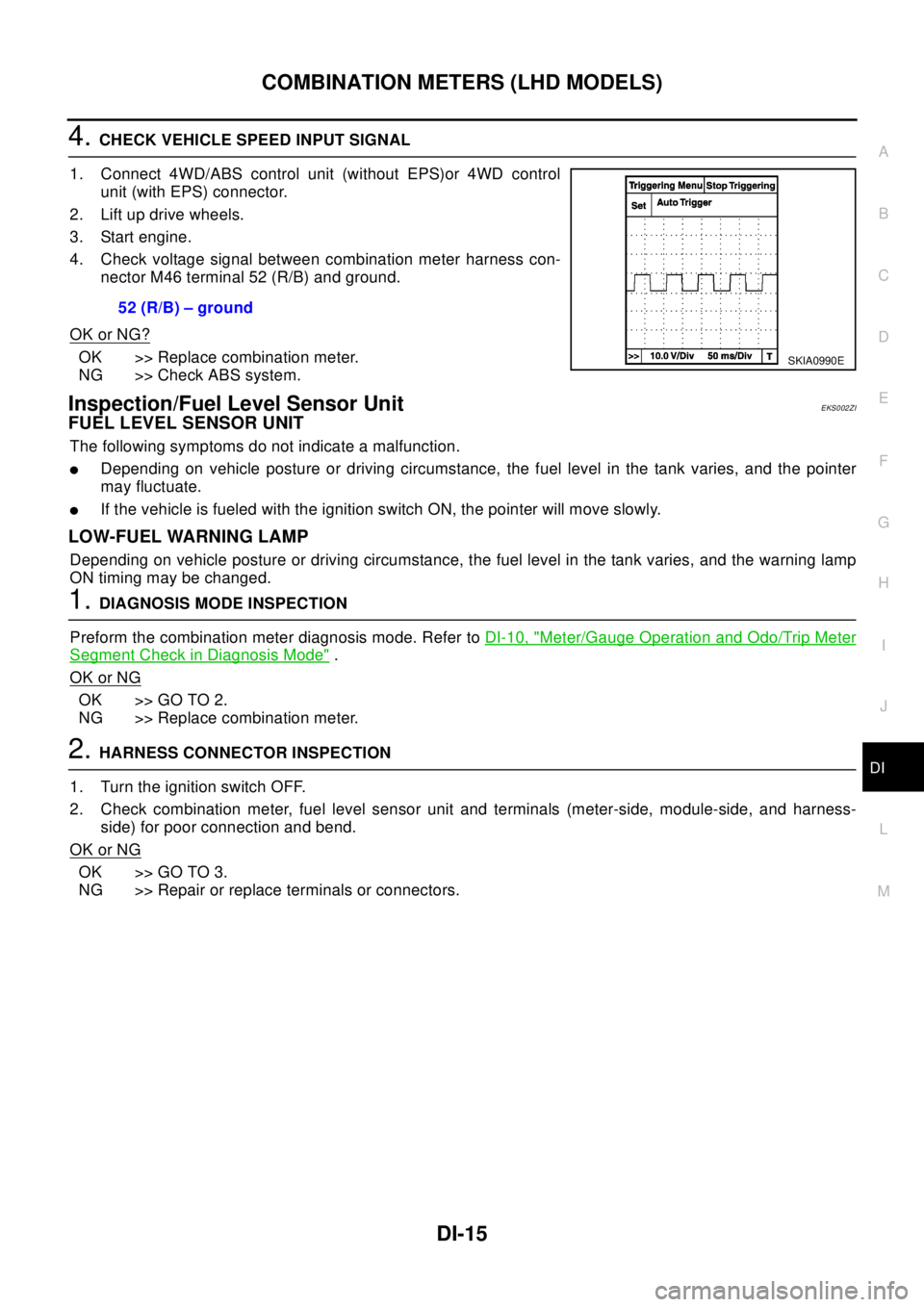
4.CHECK VEHICLE SPEED INPUT SIGNAL
1. Connect 4WD/ABS control unit (without EPS)or 4WD control
unit (with EPS) connector.
2. Lift up drive wheels.
3. Start engine.
4. Check voltage signal between combination meter harness con-
nector M46 terminal 52 (R/B) and ground.
OK or NG?
OK >> Replace combination meter.
NG >> Check ABS system.
Inspection/Fuel Level Sensor UnitEKS002ZI
FUEL LEVEL SENSOR UNIT
The following symptoms do not indicate a malfunction.
lDepending on vehicle posture or driving circumstance, the fuel level in the tank varies, and the pointer
may fluctuate.
lIf the vehicle is fueled with the ignition switch ON, the pointer will move slowly.
LOW-FUEL WARNING LAMP
Depending on vehicle posture or driving circumstance, the fuel level in the tank varies, and the warning lamp
ON timing may be changed.
1.DIAGNOSIS MODE INSPECTION
Preform the combination meter diagnosis mode. Refer toDI-10, "
Meter/Gauge Operation and Odo/Trip Meter
Segment Check in Diagnosis Mode".
OK or NG
OK >> GO TO 2.
NG >> Replace combination meter.
2.HARNESS CONNECTOR INSPECTION
1. Turn the ignition switch OFF.
2. Check combination meter, fuel level sensor unit and terminals (meter-side, module-side, and harness-
side) for poor connection and bend.
OK or NG
OK >> GO TO 3.
NG >> Repair or replace terminals or connectors.52 (R/B) – ground
SKIA0990E
Page 1073 of 3066
COMBINATION METERS (LHD MODELS)
DI-19
C
D
E
F
G
H
I
J
L
MA
B
DI
Low Fuel Warning Lamp Illuminate or Not IlluminateEKS002ZM
1.DIAGNOSIS MODE INSPECTION
Preform combination meter diagnosis mode. Refer toDI-10, "
Meter/Gauge Operation and Odo/Trip Meter
Segment Check in Diagnosis Mode".
OK or NG
OK >> Check fuel level sensor unit or sub fuel level sensor unit. Refer toDI-19, "Electrical Components
Inspection".
NG >> Replace combination meter.
Electrical Components InspectionEKS002ZN
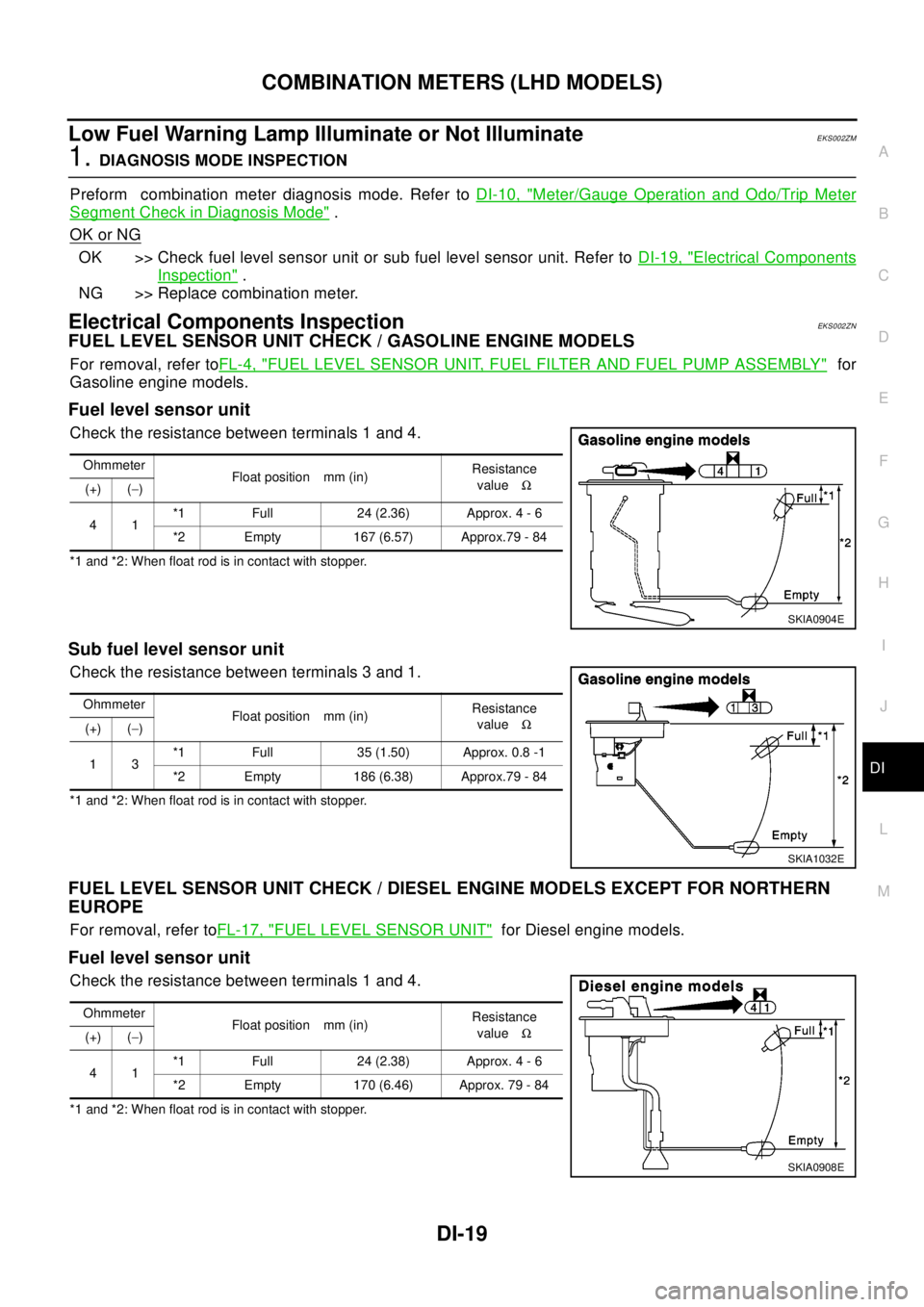
FUEL LEVEL SENSOR UNIT CHECK / GASOLINE ENGINE MODELS
For removal, refer toFL-4, "FUEL LEVEL SENSOR UNIT, FUEL FILTER AND FUEL PUMP ASSEMBLY"for
Gasoline engine models.
Fuel level sensor unit
Check the resistance between terminals 1 and 4.
*1 and *2: When float rod is in contact with stopper.
Sub fuel level sensor unit
Check the resistance between terminals 3 and 1.
*1 and *2: When float rod is in contact with stopper.
FUEL LEVEL SENSOR UNIT CHECK / DIESEL ENGINE MODELS EXCEPT FOR NORTHERN
EUROPE
For removal, refer toFL-17, "FUEL LEVEL SENSOR UNIT"for Diesel engine models.
Fuel level sensor unit
Check the resistance between terminals 1 and 4.
*1 and *2: When float rod is in contact with stopper.Ohmmeter
Float position mm (in)Resistance
valueW
(+) (-)
41*1 Full 24 (2.36) Approx. 4 - 6
*2 Empty 167 (6.57) Approx.79 - 84
SKIA0904E
Ohmmeter
Float position mm (in)Resistance
valueW
(+) (-)
13*1 Full 35 (1.50) Approx. 0.8 -1
*2 Empty 186 (6.38) Approx.79 - 84
SKIA1032E
Ohmmeter
Float position mm (in)Resistance
valueW
(+) (-)
41*1 Full 24 (2.38) Approx. 4 - 6
*2 Empty 170 (6.46) Approx. 79 - 84
SKIA0908E
Page 1082 of 3066
DI-28
COMBINATION METERS (RHD MODELS)
Meter/Gauge Operation and Odo/Trip Meter Segment Check in Diagnosis Mode
EKS0030M
DIAGNOSIS FUNCTION
lOdo/trip meter segment can be checked in diagnosis mode.
lMeters/gauges can be checked in diagnosis mode.
HOW TO ALTERNATE DIAGNOSIS MODE
1. Turn ignition switch to ON and change odo/trip meter to “TRIP A” or “TRIP B”.
2. Turn ignition switch to OFF.
3. Turn ignition switch to ON when pushing odo/trip meter switch.
4. Confirm that trip meter indicates “000.0”.
5. Push odo/trip meter switch more than three times within 5 seconds.
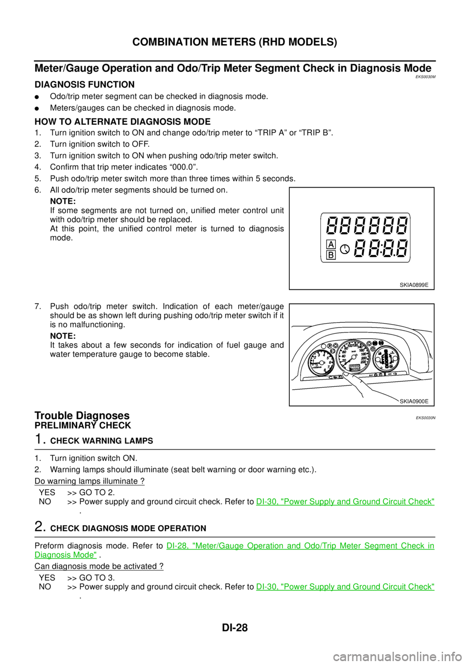
6. All odo/trip meter segments should be turned on.
NOTE:
If some segments are not turned on, unified meter control unit
with odo/trip meter should be replaced.
At this point, the unified control meter is turned to diagnosis
mode.
7. Push odo/trip meter switch. Indication of each meter/gauge
should be as shown left during pushing odo/trip meter switch if it
is no malfunctioning.
NOTE:
It takes about a few seconds for indication of fuel gauge and
water temperature gauge to become stable.
Trouble DiagnosesEKS0030N
PRELIMINARY CHECK
1.CHECK WARNING LAMPS
1. Turn ignition switch ON.
2. Warning lamps should illuminate (seat belt warning or door warning etc.).
Do warning lamps illuminate ?
YES >> GO TO 2.
NO >> Power supply and ground circuit check. Refer toDI-30, "
Power Supply and Ground Circuit Check"
.
2.CHECK DIAGNOSIS MODE OPERATION
Preform diagnosis mode. Refer toDI-28, "
Meter/Gauge Operation and Odo/Trip Meter Segment Check in
Diagnosis Mode".
Can diagnosis mode be activated ?
YES >> GO TO 3.
NO >> Power supply and ground circuit check. Refer toDI-30, "
Power Supply and Ground Circuit Check"
.
SKIA0899E
SKIA0900E
Page 1083 of 3066
COMBINATION METERS (RHD MODELS)
DI-29
C
D
E
F
G
H
I
J
L
MA
B
DI
3.SEGMENTS CHECK
Check odo/trip meter segment.
Do all segments illuminate ?
YES >> GO TO 4.
NO >> Replace combination meter.
4.CHECK FUEL WARNING LAMP
Check fuel warning lamp in diagnosis mode. Refer toDI-28, "
Meter/Gauge Operation and Odo/Trip Meter
Segment Check in Diagnosis Mode".
Do fuel warning lamp illuminate?
OK >> GO TO 5.
NG >> Replace combination meter.
5.CHECK METER CIRCUIT
Check indication of each meter/gauge in diagnosis mode. Refer toDI-28, "
Meter/Gauge Operation and Odo/
Trip Meter Segment Check in Diagnosis Mode".
OK or NG ?
OK >> GO TO symptom chart.
NG >> Replace combination meter.
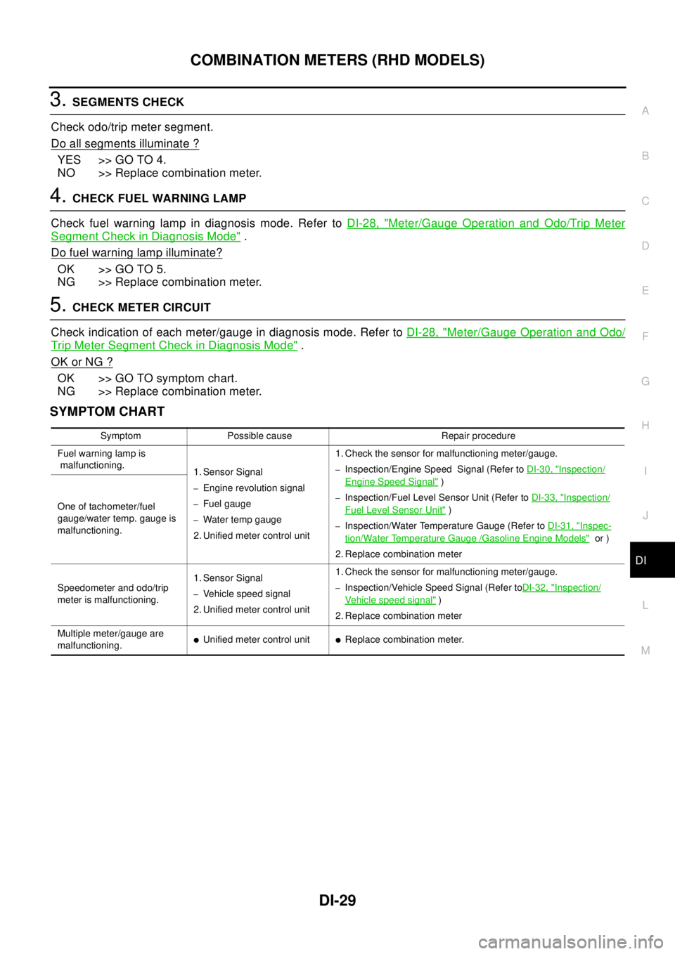
SYMPTOM CHART
Symptom Possible cause Repair procedure
Fuel warning lamp is
malfunctioning.
1. Sensor Signal
–Engine revolution signal
–Fuel gauge
–Water temp gauge
2. Unified meter control unit1. Check the sensor for malfunctioning meter/gauge.
–Inspection/Engine Speed Signal (Refer toDI-30, "Inspection/
Engine Speed Signal")
–Inspection/Fuel Level Sensor Unit (Refer toDI-33, "Inspection/
Fuel Level Sensor Unit")
–Inspection/Water Temperature Gauge (Refer toDI-31, "Inspec-
tion/Water Temperature Gauge /Gasoline Engine Models"or )
2. Replace combination meter One of tachometer/fuel
gauge/water temp. gauge is
malfunctioning.
Speedometer and odo/trip
meter is malfunctioning.1. Sensor Signal
–Vehicle speed signal
2. Unified meter control unit1. Check the sensor for malfunctioning meter/gauge.–Inspection/Vehicle Speed Signal (Refer toDI-32, "Inspection/
Vehicle speed signal")
2. Replace combination meter
Multiple meter/gauge are
malfunctioning.
lUnified meter control unitlReplace combination meter.
Page 1086 of 3066
DI-32
COMBINATION METERS (RHD MODELS)
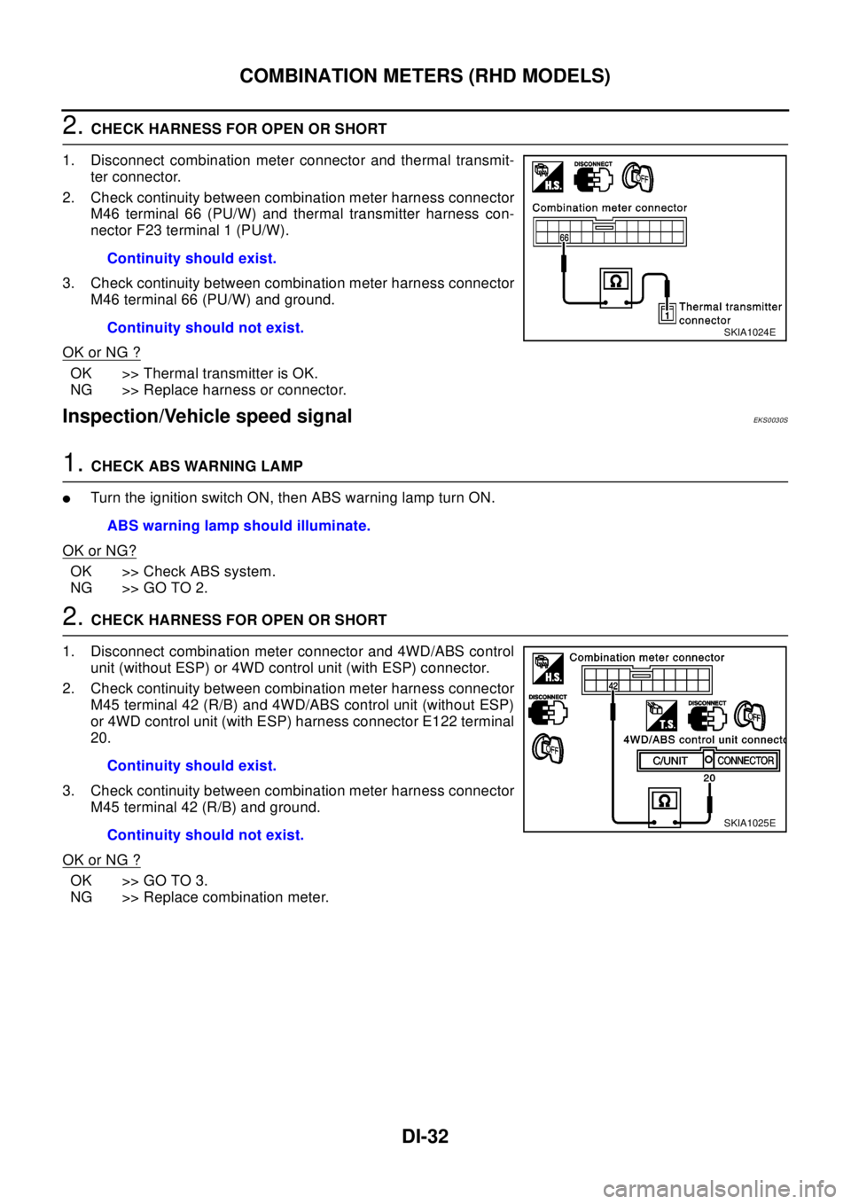
2.CHECK HARNESS FOR OPEN OR SHORT
1. Disconnect combination meter connector and thermal transmit-
ter connector.
2. Check continuity between combination meter harness connector
M46 terminal 66 (PU/W) and thermal transmitter harness con-
nector F23 terminal 1 (PU/W).
3. Check continuity between combination meter harness connector
M46 terminal 66 (PU/W) and ground.
OK or NG ?
OK >> Thermal transmitter is OK.
NG >> Replace harness or connector.
Inspection/Vehicle speed signalEKS0030S
1.CHECK ABS WARNING LAMP
lTurntheignitionswitchON,thenABSwarninglampturnON.
OK or NG?
OK >> Check ABS system.
NG >> GO TO 2.
2.CHECK HARNESS FOR OPEN OR SHORT
1. Disconnect combination meter connector and 4WD/ABS control
unit (without ESP) or 4WD control unit (with ESP) connector.
2. Check continuity between combination meter harness connector
M45 terminal 42 (R/B) and 4WD/ABS control unit (without ESP)
or 4WD control unit (with ESP) harness connector E122 terminal
20.
3. Check continuity between combination meter harness connector
M45 terminal 42 (R/B) and ground.
OK or NG ?
OK >> GO TO 3.
NG >> Replace combination meter.Continuity should exist.
Continuity should not exist.
SKIA1024E
ABS warning lamp should illuminate.
Continuity should exist.
Continuity should not exist.
SKIA1025E
Page 1087 of 3066
COMBINATION METERS (RHD MODELS)
DI-33
C
D
E
F
G
H
I
J
L
MA
B
DI
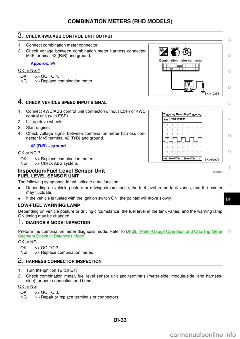
3.CHECK 4WD/ABS CONTROL UNIT OUTPUT
1. Connect combination meter connector.
2. Check voltage between combination meter harness connector
M45 terminal 42 (R/B) and ground.
OK or NG ?
OK >> GO TO 4.
NG >> Replace combination meter.
4.CHECK VEHICLE SPEED INPUT SIGNAL
1. Connect 4WD/ABS control unit connector(without ESP) or 4WD
control unit (with ESP).
2. Lift up drive wheels.
3. Start engine.
4. Check voltage signal between combination meter harness con-
nector M45 terminal 42 (R/B) and ground.
OK or NG ?
OK >> Replace combination meter.
NG >> Check ABS system.
Inspection/Fuel Level Sensor UnitEKS0030T
FUEL LEVEL SENSOR UNIT
The following symptoms do not indicate a malfunction.
lDepending on vehicle posture or driving circumstance, the fuel level in the tank varies, and the pointer
may fluctuate.
lIf the vehicle is fueled with the ignition switch ON, the pointer will move slowly.
LOW-FUEL WARNING LAMP
Depending on vehicle posture or driving circumstance, the fuel level in the tank varies, and the warning lamp
ON timing may be changed.
1.DIAGNOSIS MODE INSPECTION
Preform the combination meter diagnosis mode. Refer toDI-28, "
Meter/Gauge Operation and Odo/Trip Meter
Segment Check in Diagnosis Mode".
OK or NG
OK >> GO TO 2.
NG >> Replace combination meter.
2.HARNESS CONNECTOR INSPECTION
1. Turn the ignition switch OFF.
2. Check combination meter, fuel level sensor unit and terminals (meter-side, module-side, and harness-
side) for poor connection and bend.
OK or NG
OK >> GO TO 3.
NG >> Repair or replace terminals or connectors.Apporox. 9V
SKIA1026E
42 (R/B) – ground
SKIA0990E
Page 1091 of 3066
COMBINATION METERS (RHD MODELS)
DI-37
C
D
E
F
G
H
I
J
L
MA
B
DI
Low Fuel Warning Lamp Illuminate or Not IlluminateEKS0030X
1.DIAGNOSIS MODE INSPECTION
Preform combination meter diagnosis mode. Refer toDI-28, "
Meter/Gauge Operation and Odo/Trip Meter
Segment Check in Diagnosis Mode".
OK or NG
OK >> Check fuel level sensor unit or sub fuel level sensor unit. Refer toDI-37, "Electrical Components
Inspection".
NG >> Replace combination meter.
Electrical Components InspectionEKS0031V
FUEL LEVEL SENSOR UNIT CHECK / GASOLINE ENGINE MODELS
For removal, refer toFL-4, "FUEL LEVEL SENSOR UNIT, FUEL FILTER AND FUEL PUMP ASSEMBLY"for
Gasoline engine models.
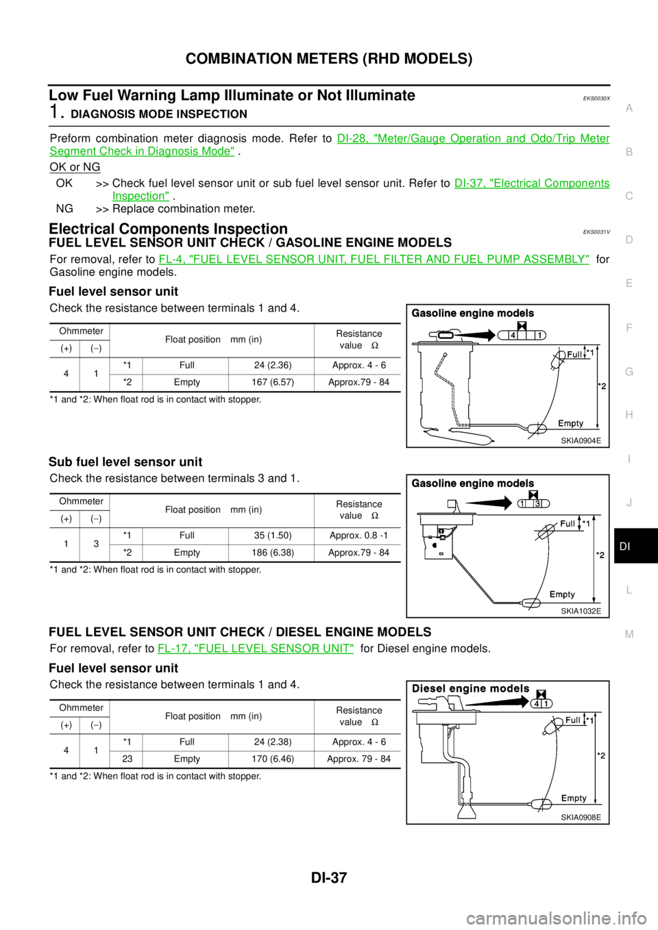
Fuel level sensor unit
Check the resistance between terminals 1 and 4.
*1 and *2: When float rod is in contact with stopper.
Sub fuel level sensor unit
Check the resistance between terminals 3 and 1.
*1 and *2: When float rod is in contact with stopper.
FUEL LEVEL SENSOR UNIT CHECK / DIESEL ENGINE MODELS
For removal, refer toFL-17, "FUEL LEVEL SENSOR UNIT"for Diesel engine models.
Fuel level sensor unit
Check the resistance between terminals 1 and 4.
*1 and *2: When float rod is in contact with stopper.Ohmmeter
Float position mm (in)Resistance
valueW
(+) (-)
41*1 Full 24 (2.36) Approx. 4 - 6
*2 Empty 167 (6.57) Approx.79 - 84
SKIA0904E
Ohmmeter
Float position mm (in)Resistance
valueW
(+) (-)
13*1 Full 35 (1.50) Approx. 0.8 -1
*2 Empty 186 (6.38) Approx.79 - 84
SKIA1032E
Ohmmeter
Float position mm (in)Resistance
valueW
(+) (-)
41*1 Full 24 (2.38) Approx. 4 - 6
23 Empty 170 (6.46) Approx. 79 - 84
SKIA0908E
Page 1093 of 3066
WARNING LAMPS
DI-39
C
D
E
F
G
H
I
J
L
MA
B
DI
WA RN IN G LA M PSPFP:24814
SchematicEKS002HE
TKWA0090E