2003 NISSAN X-TRAIL warning
[x] Cancel search: warningPage 1781 of 3066
![NISSAN X-TRAIL 2003 Electronic Repair Manual ON BOARD DIAGNOSTIC (OBD) SYSTEM
EC-667
[YD]
C
D
E
F
G
H
I
J
K
L
MA
EC
Therefore, be sure to receive all keys from vehicle owner. Regarding the procedure of NATS initial-
ization and NATS ignition key NISSAN X-TRAIL 2003 Electronic Repair Manual ON BOARD DIAGNOSTIC (OBD) SYSTEM
EC-667
[YD]
C
D
E
F
G
H
I
J
K
L
MA
EC
Therefore, be sure to receive all keys from vehicle owner. Regarding the procedure of NATS initial-
ization and NATS ignition key](/manual-img/5/57402/w960_57402-1780.png)
ON BOARD DIAGNOSTIC (OBD) SYSTEM
EC-667
[YD]
C
D
E
F
G
H
I
J
K
L
MA
EC
Therefore, be sure to receive all keys from vehicle owner. Regarding the procedure of NATS initial-
ization and NATS ignition key ID registration, refer to CONSULT-II operation manual, NATS.
Malfunction Indicator (MI)EBS0036Q
DESCRIPTION
The MI is located on the instrument panel.
1. The MI will light up when the ignition switch is turned ON without
the engine running. This is a bulb check.
lIf the MI does not light up, refer toDI-39, "WARNING LAMPS"
or seeEC-825.
2. When the engine is started, the MI should go off.
If the MI remains on, the on board diagnostic system has
detected an engine system malfunction.
On Board Diagnostic System Function
The on board diagnostic system has the following two functions.
Diagnostic Test Mode I - Bulb Check
In this mode, the MI on the instrument panel should stay ON. If it remains OFF, check the bulb. Refer toDI-39,
"WA RN ING LA MPS"or seeEC-825.
Diagnostic Test Mode I - Malfunction Warning
SAT652J
Diagnostic Test
ModeKEY and ENG.
Sta tusFunction Explanation of Function
Mode I Ignition switch in
ON position
Engine stoppedBULB CHECK This function checks the MI bulb for damage (blown, open
circuit, etc.).
IftheMIdoesnotcomeon,checkMIcircuit.(SeeEC-825,
"MI&DATA LINK CONNECTORS".)
Engine running MALFUNCTION
WARN IN GThis is a usual driving condition. When ECM detects a mal-
function, the MI will light up to inform the driver that a mal-
function has been detected.
MI Condition
ON When the malfunction is detected or the ECM's CPU is malfunctioning.
OFF No malfunction.
Page 1914 of 3066
![NISSAN X-TRAIL 2003 Electronic Repair Manual EC-800
[YD]
GLOW CONTROL SYSTEM
7.CHECK GLOW INDICATOR LAMP OUTPUT SIGNAL CIRCUIT FOR OPEN AND SHORT
1. Turn ignition switch “OFF”.
2. Disconnect ECM harness connector.
3. Check harness continuity NISSAN X-TRAIL 2003 Electronic Repair Manual EC-800
[YD]
GLOW CONTROL SYSTEM
7.CHECK GLOW INDICATOR LAMP OUTPUT SIGNAL CIRCUIT FOR OPEN AND SHORT
1. Turn ignition switch “OFF”.
2. Disconnect ECM harness connector.
3. Check harness continuity](/manual-img/5/57402/w960_57402-1913.png)
EC-800
[YD]
GLOW CONTROL SYSTEM
7.CHECK GLOW INDICATOR LAMP OUTPUT SIGNAL CIRCUIT FOR OPEN AND SHORT
1. Turn ignition switch “OFF”.
2. Disconnect ECM harness connector.
3. Check harness continuity between ECM terminal D2 and combination meter terminal 65 or 55. Refer to
Wiring Diagram.
4. Also check harness for short to ground and short to power.
OK or NG
OK >> GO TO 9.
NG >> GO TO 8.
8.DETECT MALFUNCTIONING PART
Check the following.
lHarness connectors M63, F30
lHarness for open or short between combination meter and ECM
>> Repair open circuit or short to ground or short to power in harness or connectors.
9.CHECK COMBINATION METER
Check combination meter and glow indicator lamp. Refer toDI-4, "
COMBINATION METERS (LHD MODELS)"
orDI-22, "COMBINATION METERS (RHD MODELS)"andDI-39, "WARNING LAMPS".
OK or NG
OK >> GO TO 17.
NG >> Repair or replace combination meter or glow indicator lamp.
10.CHECK GLOW RELAY POWER SUPPLY CIRCUIT
1. Turn ignition switch “OFF”.
2. Disconnect glow relay.
3. Check voltage between glow relay terminals 1, 3 and ground
with CONSULT-II or tester.
OK or NG
OK >> GO TO 12.
NG >> GO TO 11.Continuity should exist.
PBIB0373E
Voltage: Battery voltage
PBIB0427E
Page 2359 of 3066
IDX-2
ALPHABETICAL INDEX
Numerics
4WD mode switch ...................................TF-53
,TF-57
4WD shift indicator lamp .........................TF-32,TF-54
4WD solenoid valve ................................TF-49,TF-51
4WD warning lamp ..........TF-32,TF-40,TF-55,TF-58
A
A/C air flow .........................................ATC-28
,MTC-5
A/C component layout .....................................ATC-20
A/C compressor clutch removal and installation ...........
ATC-129
A/C compressor precaution ...............................ATC-7
A/C compressor special service tool ................ATC-11
A/C diagnostic work flow (auto A/C) ................ATC-30
A/C HFC134a (R134a) system precaution ........ATC-4
A/C HFC134a (R134a) system service procedure .......
ATC-123
A/C HFC134a (R134a) system service tools ...ATC-12
A/C HFC134a system service equipment precaution ...
ATC-8
A/C lubricant (R134a) ......................................ATC-21
A/C operational check .........................ATC-51,MTC-7
A/C performance test diagnoses .....................ATC-83
A/C reray ..........................................................ATC-80
A/C self-diagnoses (auto A/C) .........................ATC-42
A/C service data specification ........................ATC-143
A/C system description (auto A/C) ...................ATC-24
A/C trouble diagnoses (auto A/C) .......ATC-30,MTC-3
A/C, A - Wiring diagram ...................................ATC-35
A/CCUT - Wiring diagram ................................EC-824
A/T - Wiring diagram - AT - FTS ......................AT-138
A/T - Wiring diagram - AT - MAIN ....................AT-389
A/T - Wiring diagram - AT - PNP/SW ...............AT-132
A/T - Wiring diagram - AT - VSS A/T .AT-144,AT-394
A/T fluid checking ..................................AT-13,MA-36
A/T fluid replacement .............................AT-13,MA-36
A/T fluid temperature sensor ...........................AT-141
A/T IND - Wiring diagram ....................................DI-51
A/T indicator ........................................................DI-51
A/T shift lock system ........................................AT-446
A/T shift lock system - Wiring diagram ............AT-447
A/T trouble diagnoses ..........................AT-56,AT-279
A/T Wiring diagram - AT - ENG SS ...AT-148,AT-433
A/T Wiring diagram AT - 1ST ...........................AT-154
A/T Wiring diagram AT - 2ND ..........................AT-161
A/T Wiring diagram AT - 3RD ..........................AT-168
A/T Wiring diagram AT - 4TH ..........................AT-175
A/T Wiring diagram AT - BA/FTS .......AT-218,AT-428
A/T Wiring diagram AT - LPSV ..........AT-188,AT-438
A/T Wiring diagram AT - OVRCSV ....AT-210,AT-418
A/T Wiring diagram AT - SSV/A .........AT-195,AT-408
A/T Wiring diagram AT - SSV/B .........AT-200,AT-413
A/T Wiring diagram AT - TCV ............AT-183,AT-423
A/T Wiring diagram AT - TPS ............AT-205,AT-403
A/T Wiring diagrawm AT - VSSMTR ..AT-224,AT-399
ABS - Wiring diagram .....................................BRC-12
Absolute pressure sensor ................................EC-749
Accelerator control system ...............................ACC-2
Accelerator pedal position (APP) sensor ........EC-154,
EC-484
,EC-715
Accelerator pedal released position learning ...EC-664
Accelerator pedal released position switch ......EC-783
Actuator relay .....................................................TF-51
Aiming adjustment ...............................................LT-4
Air bag ..............................................................SRS-3
Air bag disposal ..............................................SRS-40
Air bleeding (hydraulic clutch) ..............................CL-8
Air bleeding for brake system ............................BR-10
Air cleaner and air duct(QR20DE) ....................EM-15
Air cleaner and air duct(YD22DDTi) ...............EM-112
Air cleaner filter replacement(QR20DE) ...........MA-23
Air cleaner filter replacement(YD22DDTi) .........MA-31
Air cleaner filter(QR20DE) ................................EM-15
Air cleaner filter(YD22DDTi) ...........................EM-112
Air conditioner cut control .....EC-27,EC-392,EC-662
Air flow meter - See Mass air flow sensor .......EC-130,
EC-260
,EC-463
Air mix door control linkage adjustment .........ATC-64,
ATC-119
,MTC-9,MTC-28
Air mix. door motor .........................ATC-61,ATC-119
Air spoiler, rear ...................................................EI-21
Alternator ...........................................................SC-12
Ambient sensor .................ATC-93,ATC-95,ATC-105
Angular tightening application(QR20DE) ............EM-5
Angular tightening application(YD22DDTi) .....EM-102
Antenna - See Power antenna ...........................AV-15
APPS - Wiring diagram .......EC-156,EC-486,EC-717
APRSW - Wiring diagram ................................EC-785
Audio ....................................................................AV-3
Auto air conditioner - Wiring diagram .............ATC-35
Automatic amplifier ...........................ATC-41,ATC-53
Automatic transmission fluid replacement .......MA-35,
MA-37
Axle ...................................................................MA-41
B
Back door ...........................................................BL-60
Back door trim .....................................................EI-25
Back door window ..............................................GW-7
Back window ......................................................GW-7
BACK/L - Wiring diagram ...................................LT-28
Back-up lamp ..........................................LT-28,LT-42
Back-up lamp switch (M/T) ...............................MT-13
Basic inspection ....................EC-64,EC-412,EC-672
Battery .................................................................SC-3
Baulk ring (M/T) ....................................MT-19,MT-24
Blower motor .....ATC-67,ATC-73,ATC-111,MTC-13,
MTC-17
,MTC-20
Blower resistor ................................................MTC-21
Blower unit .....................................ATC-109,MTC-20
Brake booster ....................................................BR-17
Brake fluid change ...............................................BR-9
Brake fluid level ................................................MA-38
Page 2365 of 3066
IDX-8
ALPHABETICAL INDEX
SRS - See Supplemental Restraint System .....SRS-5
SRS - Wiring diagram/LHD .............................SRS-10
SRS - Wiring diagram/RHD ............................SRS-12
SRS Trouble diagnoses ....................................SRS-7
Stall test (A/T) ......................................AT-65,AT-287
Standardized relay .............................................PG-74
START - Wiring diagram ........................SC-22,SC-23
Start signal ..........................EC-348,EC-623,EC-818
Starter ................................................................SC-21
Starting system ..................................................SC-21
Steering gear and linkage inspection ................MA-40
Steering knuckle ................................................FAX-7
Steering linkage .................................................PS-12
Steering wheel and column .......................PS-6,PS-9
Stop lamp ................................................LT-26,LT-42
Stop lamp switch ................................EC-329,EC-562
STOP/L - Wiring diagram ........................LT-26,LT-42
Strut (rear) ........................................................RSU-8
Suction control valve ........................................EC-772
Sunload sensor ...............ATC-98,ATC-100,ATC-107
Sunroof ................................................................RF-2
Super lock ..........................................................BL-24
Supplemental Restraint System .......................SRS-5
Supplemental restraint system - Wiring diagram/LHD ..
SRS-10
Supplemental restraint system - Wiring diagram/RHD .
SRS-12
Suspension .......................................................MA-41
Symbols and abbreviations .................................GI-22
Symptom matrix chart ...........EC-69,EC-417,EC-676
Synchronizer (M/T) ...............................MT-19,MT-24
System readiness test (SRT) code ....................EC-40
T
T/MTR - Wiring diagram ....................EC-275
,EC-538
Tachometer ................................................DI-4,DI-22
Tail lamp .................................................LT-30,LT-40
TAIL/L - Wiring diagram ......................................LT-30
Tailgate lamp ......................................................LT-30
TCM circuit diagram ...........................................AT-16
TCM inspection table .........................AT-126,AT-348
THEFT - Wiring diagram ....................................BL-65
Theft warning system .........................................BL-65
Thermal protector ............................................ATC-81
Thermostat(QR20DE) .......................................CO-21
Thermostat(YD22DDTi) ....................................CO-43
Three way catalyst function .............................EC-229
Three way catalyst(QR20DE) ...........................EM-22
Throttle control motor relay ................EC-279,EC-542
Throttle position sensor (TPS) ...........EC-146,EC-475
Throttle position switch ......................AT-266,AT-388
Time control system ..........................................BCS-3
Timing chain(QR20DE) .....................................EM-43
Timing chain(YD22DDTi) ..................EM-158,EM-163
TM/RLY - Wiring diagram ..................EC-281,EC-544
Torque converter installation .............AT-459,AT-556
TPS - Wiring diagram ........................EC-149,EC-479
Transfer case .....................................................TF-23
Transfer control unit inspection table ......TF-42,TF-49
Transmission case (M/T) ......................MT-18,MT-23
Trouble diagnoses ..............................................GI-10
Turbocharger charge air cooler(YD22DDTi) ...EM-114
Turbocharger(YD22DDTi) ...............................EM-119
TURN - Wiring diagram ..........................LT-17,LT-19
Turn signal lamp .....................................LT-17,LT-42
Two trip detection logic .......................EC-36,EC-401
V
Vacuum hose (brake system) ............................BR-19
Vacuum hose drawing (Engine control)EC-23,EC-388
Vacuum pump(YD22DDTi) .............................EM-131
Valve clearance(QR20DE) ...............................EM-40
Valve clearance(YD22DDTi) ...........................EM-154
Valve guide(QR20DE) ......................................EM-57
Valve guide(YD22DDTi) .................................EM-180
Valve lifter(QR20DE) ........................................EM-33
Valve lifter(YD22DDTi) ...................................EM-152
Valve seat(QR20DE) ........................................EM-58
Valve seat(YD22DDTi) ...................................EM-181
Valve spring(QR20DE) .....................................EM-60
Valve spring(YD22DDTi) ................................EM-183
VDC -Wiring diagram ......................................BRC-65
Vehicle speed sensor (VSS)EC-239,EC-513,EC-744
Ventilation air filter ........................................ATC-114
Viscosity number (SAE) ....................................MA-18
VSS - Wiring diagram .........EC-241,EC-515,EC-745
W
Warning chime ....................................................DI-52
Warning lamps ....................................................DI-39
Washer, front .....................................................WW-4
Washer, rear ....................................................WW-13
Water control valve(QR20DE) ..........................CO-21
Water pump(QR20DE) .....................................CO-19
Water pump(YD22DDTi) ...................................CO-40
Water temperature gauge ..........................DI-4,DI-22
Weatherstrip - See Exterior ...............................BL-10
Wheel alignment (front) ....................................FSU-6
Wheel alignment (rear) .....................................RSU-6
Wheel balance ..................................................MA-38
Wheel bearing (front axle) .................................FAX-7
Wheel bearing (rear) .........................................RAX-6
Wheel hub (front) ...............................................FAX-7
Wheel hub (rear) ...............................................RAX-6
Wheel sensor(VDC) ......................................BRC-119
Wheel sensors (ABS) .....................................BRC-48
WINDOW - Wiring diagram ..............................GW-24
Window, back ....................................................GW-7
Window, back door ............................................GW-7
Window, door ......................................GW-41,GW-43
Window, rear side ..............................................GW-5
Window, side - See Rear side window ..............GW-5
Windshield .........................................................GW-3
Page 2399 of 3066
LT-1
LIGHTING SYSTEM
K ELECTRICAL
CONTENTS
C
D
E
F
G
H
I
J
L
M
SECTION
A
B
LT
LIGHTING SYSTEM
PRECAUTION ............................................................ 3
Precautions for Supplemental Restraint System
(SRS) “AIR BAG” and “SEAT BELT PRE-TEN-
SIONER” .................................................................. 3
Precaution ................................................................ 3
Wiring Diagrams and Trouble Diagnosis .................. 3
HEADLAMP ................................................................ 4
System Description .................................................. 4
DESCRIPTION ...................................................... 4
LOW BEAM OPERATION ..................................... 4
HIGH BEAM OPERATION/FLASH-TO-PASS
OPERATION ......................................................... 4
Wiring Diagram — H/LAMP — ................................. 5
Trouble Diagnoses ................................................... 6
Aiming Adjustment ................................................... 6
LOW BEAM ........................................................... 7
Bulb Replacement .................................................... 8
HEAD LAMP ......................................................... 8
CLEARANCE LAMP ............................................. 8
Removal and Installation .......................................... 8
REMOVAL ............................................................. 8
INSTALLATION ..................................................... 8
HEADLAMP - DAYTIME LIGHT SYSTEM - ............... 9
System Description .................................................. 9
DESCRIPTION ...................................................... 9
HEADLAMP OPERATION (DAYTIME LIGHT
CANCEL OPERATION) ........................................ 9
DAYTIME LIGHT OPERATION ............................. 9
Schematic .............................................................. 10
Wiring Diagram -DTRL- ...........................................11
Trouble Diagnoses ................................................. 14
DAYTIME LIGHT UNIT INSPECTION TABLE .... 14
Bulb Replacement .................................................. 14
Aiming Adjustment ................................................. 14
HEADLAMP AIMING CONTROL ............................. 15
Wiring Diagram -H/AIM- ......................................... 15
Removal and Installation ........................................ 16
Switch Circuit Inspection ........................................ 16
TURN SIGNAL AND HAZARD WARNING LAMPS... 17System Description ................................................. 17
TURN SIGNAL OPERATION .............................. 17
HAZARD LAMP OPERATION ............................. 17
Wiring Diagram — TURN — ................................... 19
Trouble Diagnoses ................................................. 21
Electrical Components Inspection .......................... 21
COMBINATION FLASHER UNIT CHECK ........... 21
Bulb Replacement .................................................. 22
FRONT TURN SIGNAL LAMP ............................ 22
SIDE TURN SIGNAL LAMP ................................ 22
REAR TURN SIGNAL LAMP .............................. 22
Removal and Installation for Front Turn Signal Lamp... 22
REMOVAL ........................................................... 22
INSTALLATION ................................................... 22
Removal and Installation for Side Turn Signal Lamp... 23
Removal and Installation for Rear Turn Signal Lamp... 23
LIGHTING AND TURN SIGNAL SWITCH ................ 24
Removal and Installation ........................................ 24
Switch Circuit Inspection ........................................ 24
HAZARD SWITCH .................................................... 25
Removal and Installation ........................................ 25
REMOVAL ........................................................... 25
INSTALLATION ................................................... 25
STOP LAMP .............................................................. 26
Wiring Diagram — STOP/L — ................................ 26
Bulb Replacement .................................................. 27
STOP LAMP ........................................................ 27
HIGH-MOUNTED STOP LAMP ........................... 27
Removal and Installation ........................................ 27
STOP LAMP ........................................................ 27
HIGH-MOUNTED STOP LAMP ........................... 27
BACK-UP LAMP ....................................................... 28
Wiring Diagram — BACK/L — ................................ 28
Bulb Replacement .................................................. 29
Removal and Installation ........................................ 29
PARKING, LICENSE PLATE AND TAIL LAMPS ..... 30
Wiring Diagram — TAIL/L — .................................. 30
Bulb Replacement .................................................. 32
PARKING AND TAIL LAMPS .............................. 32
Page 2415 of 3066
TURN SIGNAL AND HAZARD WARNING LAMPS
LT-17
C
D
E
F
G
H
I
J
L
MA
B
LT
TURN SIGNAL AND HAZARD WARNING LAMPSPFP:26120
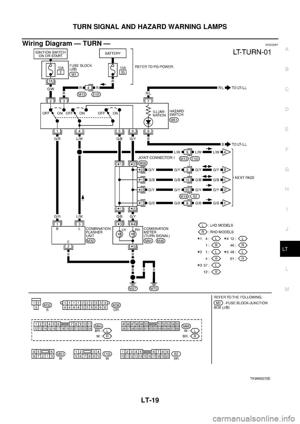
System DescriptionEKS003BX
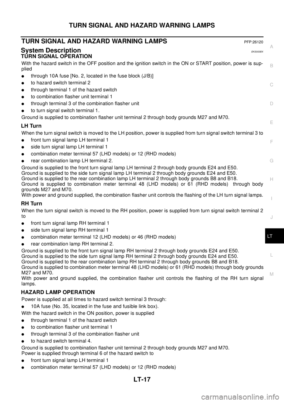
TURN SIGNAL OPERATION
With the hazard switch in the OFF position and the ignition switch in the ON or START position, power is sup-
plied
lthrough 10A fuse [No. 2, located in the fuse block (J/B)]
lto hazard switch terminal 2
lthrough terminal 1 of the hazard switch
lto combination flasher unit terminal 1
lthrough terminal 3 of the combination flasher unit
lto turn signal switch terminal 1.
Ground is supplied to combination flasher unit terminal 2 through body grounds M27 and M70.
LH Turn
When the turn signal switch is moved to the LH position, power is supplied from turn signal switch terminal 3 to
lfront turn signal lamp LH terminal 1
lside turn signal lamp LH terminal 1
lcombination meter terminal 57 (LHD models) or 12 (RHD models)
lrear combination lamp LH terminal 2.
Ground is supplied to the front turn signal lamp LH terminal 2 through body grounds E24 and E50.
Ground is supplied to the side turn signal lamp LH terminal 2 through body grounds E24 and E50.
Ground is supplied to the rear combination lamp LH terminal 2 through body grounds B8 and B18.
Ground is supplied to combination meter terminal 48 (LHD models) or 61 (RHD models) through body
grounds M27 and M70.
With power and ground supplied, the combination flasher unit controls the flashing of the LH turn signal lamps.
RH Turn
When the turn signal switch is moved to the RH position, power is supplied from turn signal switch terminal 2
to
lfront turn signal lamp RH terminal 1
lside turn signal lamp RH terminal 1
lcombination meter terminal 12 (LHD models) or 46 (RHD models)
lrear combination lamp RH terminal 2.
Ground is supplied to the front turn signal lamp RH terminal 2 through body grounds E24 and E50.
Ground is supplied to the side turn signal lamp RH terminal 2 through body grounds E24 and E50.
Ground is supplied to the rear combination lamp RH terminal 2 through body grounds B8 and B18.
Ground is supplied to combination meter terminal 48 (LHD models) or 61 (RHD models) through body grounds
M27 and M70.
With power and ground supplied, the combination flasher unit controls the flashing of the RH turn signal
lamps.
HAZARD LAMP OPERATION
Power is supplied at all times to hazard switch terminal 3 through:
l10A fuse (No. 35, located in the fuse and fusible link box).
With the hazard switch in the ON position, power is supplied
lthrough terminal 1 of the hazard switch
lto combination flasher unit terminal 1
lthrough terminal 3 of the combination flasher unit
lto hazard switch terminal 4.
Ground is supplied to combination flasher unit terminal 2 through body grounds M27 and M70.
Power is supplied through terminal 6 of the hazard switch to
lfront turn signal lamp LH terminal 1
lcombination meter terminal 57 (LHD models) or 12 (RHD models)
Page 2416 of 3066

LT-18
TURN SIGNAL AND HAZARD WARNING LAMPS
lrear combination lamp LH terminal 2.
Power is supplied through terminal 6 of the hazard switch to
lfront turn signal lamp RH terminal 1
lcombination meter terminal 12 (LHD models) or 46 (RHD models)
lrear combination lamp RH terminal 2.
Ground is supplied to terminal 2 of each front turn signal lamp through body grounds E24 and E50.
Ground is supplied to terminal 4 of each rear combination lamp through body grounds B8 and B18.
Ground is supplied to combination meter terminal 48 (LHD models) or 61 (RHD models) through body
grounds M27 and M27.
With power and ground supplied, the combination flasher unit controls the flashing of the hazard warning
lamps.
Page 2417 of 3066
TURN SIGNAL AND HAZARD WARNING LAMPS
LT-19
C
D
E
F
G
H
I
J
L
MA
B
LT
Wiring Diagram — TURN —EKS003BY
TKWA0072E