Page 2418 of 3066
LT-20
TURN SIGNAL AND HAZARD WARNING LAMPS
TKWA0073E
Page 2419 of 3066

TURN SIGNAL AND HAZARD WARNING LAMPS
LT-21
C
D
E
F
G
H
I
J
L
MA
B
LT
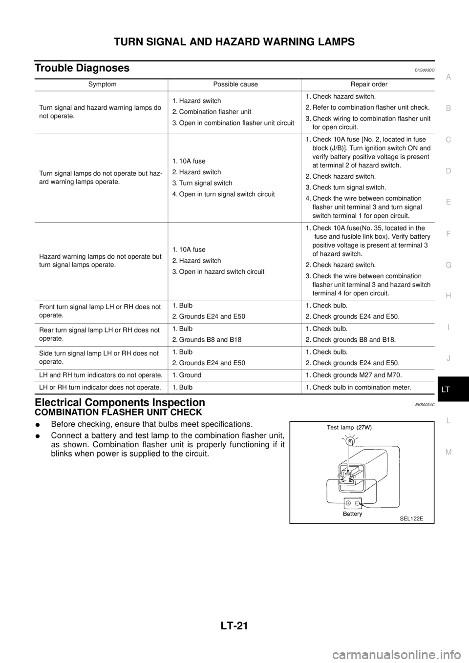
Trouble DiagnosesEKS003BG
Electrical Components InspectionEKS0034C
COMBINATION FLASHER UNIT CHECK
lBefore checking, ensure that bulbs meet specifications.
lConnect a battery and test lamp to the combination flasher unit,
as shown. Combination flasher unit is properly functioning if it
blinks when power is supplied to the circuit.
Symptom Possible cause Repair order
Turn signal and hazard warning lamps do
not operate.1. Hazard switch
2. Combination flasher unit
3. Open in combination flasher unit circuit1. Check hazard switch.
2. Refer to combination flasher unit check.
3. Check wiring to combination flasher unit
for open circuit.
Turn signal lamps do not operate but haz-
ard warning lamps operate.1. 10A fuse
2. Hazard switch
3. Turn signal switch
4. Open in turn signal switch circuit1. Check 10A fuse [No. 2, located in fuse
block (J/B)]. Turn ignition switch ON and
verify battery positive voltage is present
at terminal 2 of hazard switch.
2. Check hazard switch.
3. Check turn signal switch.
4. Check the wire between combination
flasher unit terminal 3 and turn signal
switch terminal 1 for open circuit.
Hazard warning lamps do not operate but
turn signal lamps operate.1. 10A fuse
2. Hazard switch
3. Open in hazard switch circuit1. Check 10A fuse(No. 35, located in the
fuse and fusible link box). Verify battery
positive voltage is present at terminal 3
of hazard switch.
2. Check hazard switch.
3. Check the wire between combination
flasher unit terminal 3 and hazard switch
terminal 4 for open circuit.
Front turn signal lamp LH or RH does not
operate.1. Bulb
2. Grounds E24 and E501. Check bulb.
2. Check grounds E24 and E50.
Rear turn signal lamp LH or RH does not
operate.1. Bulb
2. Grounds B8 and B181. Check bulb.
2. Check grounds B8 and B18.
Side turn signal lamp LH or RH does not
operate.1. Bulb
2. Grounds E24 and E501. Check bulb.
2. Check grounds E24 and E50.
LH and RH turn indicators do not operate. 1. Ground 1. Check grounds M27 and M70.
LH or RH turn indicator does not operate. 1. Bulb 1. Check bulb in combination meter.
SEL122E
Page 2420 of 3066

LT-22
TURN SIGNAL AND HAZARD WARNING LAMPS
Bulb Replacement
EKS0034D
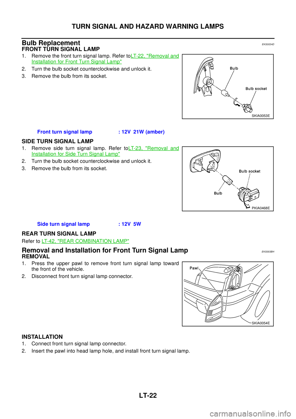
FRONT TURN SIGNAL LAMP
1. Remove the front turn signal lamp. Refer toLT- 2 2 , "Removal and
Installation for Front Turn Signal Lamp"
2. Turn the bulb socket counterclockwise and unlock it.
3. Remove the bulb from its socket.
SIDE TURN SIGNAL LAMP
1. Remove side turn signal lamp. Refer toLT- 2 3 , "Removal and
Installation for Side Turn Signal Lamp"
2. Turn the bulb socket counterclockwise and unlock it.
3. Remove the bulb from its socket.
REAR TURN SIGNAL LAMP
Refer toLT- 4 2 , "REAR COMBINATION LAMP"
Removal and Installation for Front Turn Signal LampEKS003BH
REMOVAL
1. Press the upper pawl to remove front turn signal lamp toward
the front of the vehicle.
2. Disconnect front turn signal lamp connector.
INSTALLATION
1. Connect front turn signal lamp connector.
2. Insert the pawl into head lamp hole, and install front turn signal lamp.
SKIA0053E
Front turn signal lamp : 12V 21W (amber)
PKIA0468E
Side turn signal lamp : 12V 5W
SKIA0054E
Page 2421 of 3066
TURN SIGNAL AND HAZARD WARNING LAMPS
LT-23
C
D
E
F
G
H
I
J
L
MA
B
LT
Removal and Installation for Side Turn Signal LampEKS003BI
1. Push the side turn signal lamp toward A direction in the figure,
and pull up B direction in the figure.
2. Disconnect the side turn signal lamp connector.
Removal and Installation for Rear Turn Signal LampEKS003BJ
Refer toLT- 4 2 , "REAR COMBINATION LAMP"
PKIA0469E
Page 2488 of 3066
LU-22
[YD22DDTi]
OIL FILTER BRACKET
OIL FILTER BRACKET
PFP:15238
Removal and InstallationEBS00BL8
REMOVAL
1. Remove the under cover.
2. Steer the front wheel to the right.
3. Remove the right splash cover.
4. Remove the oil filter bracket bolt. Refer toLU-20, "
OIL FILTER"for cautions.
INSTALLATION
1. Install all removed parts in the reverse order of removal.
lInsert the top mounting bolt to the oil filter bracket beforehand, and set the oil filter bracket to the installa-
tion location.
lAfter warning up the engine, check for engine oil leakage.
JLC301B
Page 2498 of 3066

MA-6
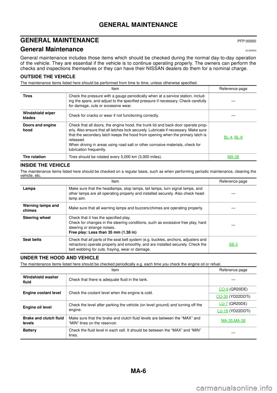
GENERAL MAINTENANCE
GENERAL MAINTENANCE
PFP:00000
General MaintenanceELS000AL
General maintenance includes those items which should be checked during the normal day-to-day operation
of the vehicle. They are essential if the vehicle is to continue operating properly. The owners can perform the
checks and inspections themselves or they can have their NISSAN dealers do them for a nominal charge.
OUTSIDE THE VEHICLE
The maintenance items listed here should be performed from time to time, unless otherwise specified.
INSIDE THE VEHICLE
The maintenance items listed here should be checked on a regular basis, such as when performing periodic maintenance, cleaning the
vehicle, etc.
UNDER THE HOOD AND VEHICLE
The maintenance items listed here should be checked periodically e.g. each time you check the engine oil or refuel.Item Reference page
TiresCheck the pressure with a gauge periodically when at a service station, includ-
ing the spare, and adjust to the specified pressure if necessary. Check carefully
for damage, cuts or excessive wear.—
Windshield wiper
bladesCheck for cracks or wear if not functioning correctly. —
Doors and engine
hoodCheck that all doors, the engine hood, the trunk lid and back door operate prop-
erly. Also ensure that all latches lock securely. Lubricate if necessary. Make sure
that the secondary latch keeps the hood from opening when the primary latch is
released.
When driving in areas using road salt or other corrosive materials, check for
lubrication frequently.BL-4
,BL-8
Tire rotationTires should be rotated every 5,000 km (3,000 miles).MA-38
Item Reference page
LampsMake sure that the headlamps, stop lamps, tail lamps, turn signal lamps, and
other lamps are all operating properly and installed securely. Also check head-
lamp aim.—
Warning lamps and
chimesMake sure that all warning lamps and buzzers/chimes are operating properly. —
Steering wheelCheck that it has the specified play.
Check for changes in the steering conditions, such as excessive free play, hard
steering or strange noises.
Free play: Less than 35 mm (1.38 in)—
Seat beltsCheck that all parts of the seat belt system (e.g. buckles, anchors, adjusters and
retractors) operate properly and smoothly, and are installed securely. Check the
belt webbing for cuts, fraying, wear or damage.SB-3
Item Reference page
Windshield washer
fluidCheck that there is adequate fluid in the tank. —
Engine coolant levelCheck the coolant level when the engine is cold.CO-9
(QR20DE)
CO-30
(YD22DDTi)
Engine oil levelCheck the level after parking the vehicle (on level ground) and turning off the
engine.LU-7
(QR20DE)
LU-18
(YD22DDTi)
Brake and clutch fluid
levelsMake sure that the brake and clutch fluid levels are between the “MAX” and
“MIN” lines on the reservoir.MA-35
,MA-38
BatteryCheck the fluid level in each cell. It should be between the “MAX” and “MIN”
lines.—
Page 2669 of 3066
PARKING BRAKE CONTROL
PB-3
C
D
E
G
H
I
J
K
L
MA
B
PB
PARKING BRAKE CONTROLPFP:36010
ComponentsEFS0017I
Removal and InstallationEFS0017J
1. Remove center console.
2. Disconnect warning lamp switch connector.
3. Remove cable mounting bolt. Loosen cable and remove self-
locking nut.
4. Remove cable from toggle lever of disc brake.
InspectionEFS0017L
lOperate parking brake lever with a force of 196 N (20 kg,44 lb). Check stroke is within specified number of
notches. (Check it by hearing clicks of ratchet.)
lCheck parking lever assembly for bend, damage and cracks, and replace if necessary.
lCheck cables and equalizer for wear and damage. If a malfunction is detected, replace applicable part.
lCheck parking brake warning lamp switch. If a malfunction is detected, replace applicable part.
SFIA0050E
1 Control lever assembly 2 Cap 3 Parking brake warning lamp switch
4 Screw 5 Self-locking nut 6 Front cable
7 RH rear cable 8 LH rear cable
SFIA0200E
Leverstroke :6-7notches
Page 2676 of 3066
PB-10
SERVICE DATA AND SPECIFICATIONS (SDS)
SERVICE DATA AND SPECIFICATIONS (SDS)
PFP:00030
Parking BrakeEFS000D2
Ty p eDS17H
Brake liningStandard thickness (new) 3.5 mm (0.138 in)
Repair limit thickness 1.5 mm (0.059 in)
Drum (disc)Standard inner diameter (new) 172 mm (6.7 7in)
Wear limit of inner diameter 173 mm (6.81 in)
Lever stroke [operating force 196 N (20 kg,44 lb)] 6 to 7 notches
To t a l s t r o k e18 notches
Brake warning lamp strokeWithin 1 notch