Page 2737 of 3066

HARNESS
PG-61
C
D
E
F
G
H
I
J
L
MA
B
PG
Wiring Diagram Codes (Cell Codes)EKS0032J
Use the chart below to find out what each wiring diagram code stands for.
Refer to the wiring diagram code in the alphabetical index to find the location (page number) of each wiring
diagram.
Code Section Wiring Diagram Name
1STSIG AT A/T 1st Signal
2NDSIG AT A/T 2nd Signal
3RDSIG AT A/T 3rd Signal
4THSIG AT A/T 4th Signal
4WD BRC 4WD Control system
A/C ATC Air Conditioner
ABS BRC ABS Control System
APPS EC Accelerator Pedal Position (APP) Sensor
APRSW EC Accelerator Pedal Released Position Sensor
AT/IND DI A/T Indicator
AUDIO AV Audio
BA/FTS AT A/T Fluid Temperature Sensor and TCM Power Supply
BACK/L LT Back-up Lamp
BRK/SW EC Brake Switch
CAN EC,AT CAN Communication Line
CAN LAN CAN System
CHARGE SC Charging System
CHIME DI Warning Chime
CIGAR WW Cigarette Lighter
CLOCK DI Clock
CKPS EC Crankshaft Position Sensor
CMPS EC Camshaft Position Sensor
COOL/F EC Cooling Fan Control
CRFPS EC Common Rail Fuel Pressure Sensor
D/LOCK BL Power Door Lock
DEF GW Rear Window Defogger
DTRL LT Headlamp - With Daytime Light System
ECM/PW EC ECM Power
ECMRLY EC ECM Relay
ECTS EC Engine Coolant Temperature Sensor
EGRC/V EC EGR Volume Control Valve
ENGSS AT Engine Speed Signal
F/FOG LT Front Fog Lamp
FIAR EC Fuel Injector Adjustment resister
FRO2 EC Heated Oxygen Sensor 1 (Front)
FRO2/H EC Heated Oxygen Sensor 1 Heater (Front)
FTS EC Fuel Temperature Sensor
FTS AT A/T Fluid Temperature Sensor
FUEL EC Fuel Injection System Function
GLOW EC Glow Control System
H/AIM LT Headlamp Aiming Control System
H/LAMP LT Headlamp
H/SEAT SE Heated Seat
HEATER MTC Heater System
HLC WW Headlamp Cleaner
HO2S1 EC Heated Oxygen Sensor 1 (Front)
Page 2738 of 3066

PG-62
HARNESS
HO2S1H EC Heated Oxygen Sensor 1 (Front)
HO2S2 EC Heated Oxygen Sensor 1 (Rear)
HO2S2H EC Heated Oxygen Sensor 1 (Rear)
HORN WW Horn
IATS EC Intake Air Temperature Sensor
IATSEN EC Intake Air Temperature Sensor
IGNSYS EC Ignition Signal
ILL LT Illumination
INJECT EC Injector
INT/L LT Map Lamp
IVC EC Intake Valve Timing Control Solenoid Valve
IVC/V EC Intake Valve Timing Control Solenoid Valve
KS EC Knock Sensor (KS)
LOAD EC Electrical Load Signal
LPSV AT Line Pressure Solenoid Valve
MAFS EC MassAirFlowSensor(MAFS)
MAIN EC, AT Main Power Supply and Ground Circuit
METER DI Meter and Gauge
MIL EC Malfunction Indicator Lamp
MIL/DL EC MIL and Data Link Connector
MIRROR GW Door Mirror
MULTI BL Multi-Remote Control System
NATS BL Nissan Anti-Theft System
NONDTC AT Non-Detective Items
OVRCSV AT Overrun Clutch Solenoid Valve
PGC/V EC EVAP Canister Purge Volume Control Solenoid Valve
PHASE EC Camshaft Position Sensor (PHASE)
PNP/SW EC, AT Park/Neutral Position (PNP) Switch
PNPSW1 EC Park/Neutral Position (PNP) Switch
POS EC Crankshaft Position Sensor (CKPS)(POS)
POWER PG Power Supply Routing
PRGVLV EC EVAP Canister Purge Volume Control Solenoid Valve
PRWIRE BL Theft Warning System (Pre-wire)
PS/SEN EC Power Steering Pressure Sensor
PST/SW EC Power Steering Oil Pressure Switch
R/FOG LT Rear Fog Lamp
ROOM/L LT Interior Room Lamp
RP/SEN EC Refrigerant Pressure Sensor
RRO2 EC Heated Oxygen Sensor 2 (Rear)
RRO2/H EC Heated Oxygen Sensor 2 Heater (Rear)
S/LOCK BL Super Lock
S/SIG EC Start Signal
SCTC/V EC Suction Control Valve
SHIFT AT A/T Shift Lock System
SROOF BL Sunroof
SRS SRS Supplemental Restraint System (SRS)
SSV/A AT Shift Solenoid Valve A
SSV/B AT Shift Solenoid Valve B
START SC Starting System
STOP/L LT Stop Lamp
T/MTR EC Throttle Control Motor
TAIL/L LT Parking, License and Tail Lamps
Page 2739 of 3066
HARNESS
PG-63
C
D
E
F
G
H
I
J
L
MA
B
PG
TCV AT Torque Converter Clutch Solenoid Valve
TM/RLY EC Throttle Control Motor Relay
TPS EC, AT Throttle Position Sensor
TURN LT Turn Signal and Hazard Warning Lamps
VDC BRC Vehicle Dynamics Control System
VSS EC Vehicle Speed Sensor (VSS)
VSSAT AT Vehicle Speed Sensor A/T (Revolution Sensor)
VSSMTR AT Vehicle Speed Sensor MTR
WARN D I Warning Lam ps
WINDOW GW Power Window
WIP/R WW Rear Wiper and Washer
WIPER WW Front Wiper and Washer
Page 2762 of 3066

PS-2
PRECAUTIONS
PRECAUTIONS
PFP:00001
Precautions for models with SRS air bag and pre-tensioner seat beltEGS00048
WAR NIN G:
lBefore removing and installing components and harnesses of SRS air bag and seat belt pre-ten-
sioner system, turn ignition switch OFF, disconnect battery ground cable, and wait at least 3 min-
utes. (This discharges electricity held in the air bag sensor unit's additional power circuit.)
lDo not use pneumatic or electric tools to remove and install the components.
lDo not solder SRS air bag and seat belt pre-tensioner system harnesses when making repairs.
Make sure harness is not pinched and there is no contact with other components.
lWhen checking the SRS air bag and the seat belt pre-tensioner circuit or the components of each
system, do not use an electric tester such as a circuit tester. (This is to prevent accidental trigger-
ing caused by the weak electric current of a tester.)
lNever insert foreign material (such as a screwdriver) in the air bag module and pre-tensioner seat
belt connectors. (The units may be actuated by mistake by static electricity.)
lSeat belt pre-tensioner and SRS air bag harnesses can be distinguished from other harnesses by
their yellow connectors.
lWhen servicing, refer to “SB Seat Belt” and “SRS Air Bag” for safety.
CautionEGS00049
lAlways follow the warnings and the cautions below in disassembly procedures:
–Work in a clean, dust-free place. No dust proof device is necessary.
–Clean outside of unit before disassembly.
–Clean parts to be disassembled. Be careful not to allow any dirt or other foreign materials to enter or con-
tact with parts.
–Assemble disassembled parts properly, following order shown in manual. If work has been suspended in
the middle of assembly, place a clean cover over parts. This will prevent them from being contaminated.
–Use paper towels when removing dirt and other foreign materials. Cloth shop towels can leave lint on
cleaned parts that might affect operation of parts.
–Clean disassembled parts (except rubber parts) with kerosene. Drain oil by blowing with air or absorbing
with shop papers.
–Before assembling, apply Nissan power steering fluid to O-rings and seals.
–Replace gaskets and O-rings with new ones. Be careful not to damage any O-rings, oil seals, and gaskets
during assembly.
lIf following part is scratched after disassembly of steering pump, replace applicable part: case, rear body,
side plate, pulley, rotor, vane, or flow control valve
lMark source of fluid leak with a white marker for identification.
lSeals and copper washers must not be reused.
Page 2767 of 3066

STEERING WHEEL
PS-7
C
D
E
F
H
I
J
K
L
MA
B
PS
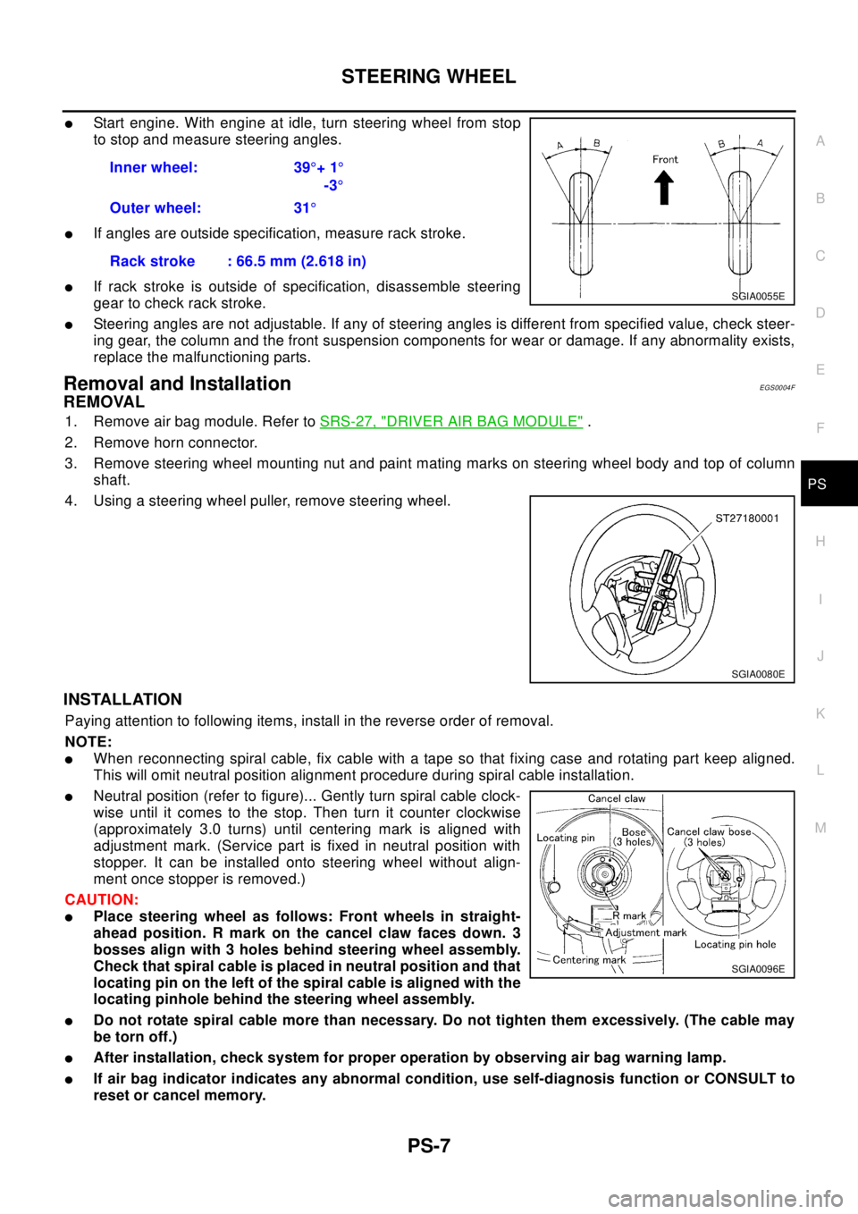
lStart engine. With engine at idle, turn steering wheel from stop
to stop and measure steering angles.
lIf angles are outside specification, measure rack stroke.
lIf rack stroke is outside of specification, disassemble steering
gear to check rack stroke.
lSteering angles are not adjustable. If any of steering angles is different from specified value, check steer-
ing gear, the column and the front suspension components for wear or damage. If any abnormality exists,
replace the malfunctioning parts.
Removal and InstallationEGS0004F
REMOVAL
1. Remove air bag module. Refer toSRS-27, "DRIVER AIR BAG MODULE".
2. Remove horn connector.
3. Remove steering wheel mounting nut and paint mating marks on steering wheel body and top of column
shaft.
4. Using a steering wheel puller, remove steering wheel.
INSTALLATION
Paying attention to following items, install in the reverse order of removal.
NOTE:
lWhen reconnecting spiral cable, fix cable with a tape so that fixing case and rotating part keep aligned.
This will omit neutral position alignment procedure during spiral cable installation.
lNeutral position (refer to figure)... Gently turn spiral cable clock-
wise until it comes to the stop. Then turn it counter clockwise
(approximately 3.0 turns) until centering mark is aligned with
adjustment mark. (Service part is fixed in neutral position with
stopper. It can be installed onto steering wheel without align-
ment once stopper is removed.)
CAUTION:
lPlace steering wheel as follows: Front wheels in straight-
ahead position. R mark on the cancel claw faces down. 3
bosses align with 3 holes behind steering wheel assembly.
Check that spiral cable is placed in neutral position and that
locating pin on the left of the spiral cable is aligned with the
locating pinhole behind the steering wheel assembly.
lDo not rotate spiral cable more than necessary. Do not tighten them excessively. (The cable may
be torn off.)
lAfter installation, check system for proper operation by observing air bag warning lamp.
lIf air bag indicator indicates any abnormal condition, use self-diagnosis function or CONSULT to
reset or cancel memory.Inner wheel: 39°+1°
-3°
Outer wheel: 31°
Rack stroke : 66.5 mm (2.618 in)
SGIA0055E
SGIA0080E
SGIA0096E
Page 2768 of 3066
PS-8
STEERING WHEEL
lIf air bag warning lamp still shows abnormal condition even after operation above, diagnose sys-
tem. Repair malfunctioning parts.
Page 2884 of 3066

SC-12
CHARGING SYSTEM
CHARGING SYSTEM
PFP:00011
System DescriptionEKS00316
The alternator provides DC voltage to operate the vehicle's electrical system and to keep the battery charged.
The voltage output is controlled by the IC regulator.
Power is supplied at all times to alternator terminal 4 (S) through:
l120A (Gasoline engine models) or 100A (Diesel engine models) fusible link (letter A, located in the fuse
and fusible link box), and
l10A fuse (No.34, located in the fuse and fusible link box).
Terminal B supplies power to charge the battery and operate the vehicle's electrical system. Output voltage is
controlled by the IC regulator at terminal 4 (S) detecting the input voltage. The charging circuit is protected by
the 120A (Gasoline engine models) or 100A (Diesel engine models) link.
The alternator is grounded to the engine block.
With the ignition switch in the ON or START position, power is supplied
l10A fuse [No. 11, located in the fuse block (J/B)]
lto combination meter terminal 46 (LHD models) or terminal 59 (RHD models) for the charge warning
lamp.
Ground is supplied With power and ground supplied
lto terminal 64 (LHD models) or terminal 54 ( RHD models) of the combination meter
lthrough terminal 3 (L) of the alternator.
the charge warning lamp will illuminate. When the alternator is providing sufficient voltage with the engine run-
ning, the ground is opened and the charge warning lamp will go off.
If the charge warning lamp illuminates with the engine running, a fault is indicated.
Page 2886 of 3066

SC-14
CHARGING SYSTEM
Trouble Diagnoses
EKS00319
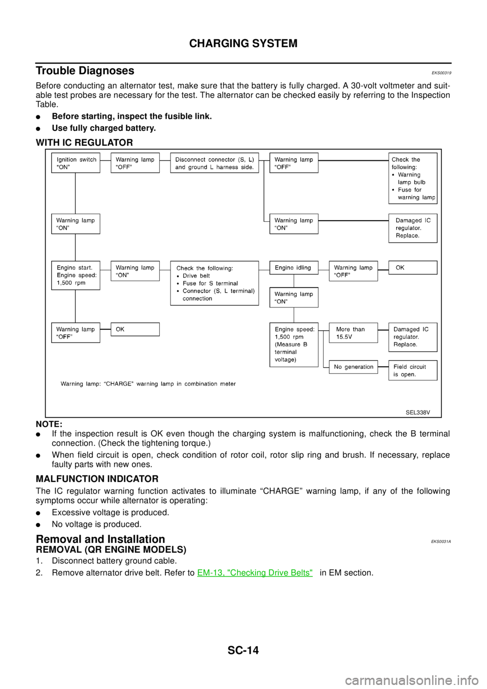
Before conducting an alternator test, make sure that the battery is fully charged. A 30-volt voltmeter and suit-
able test probes are necessary for the test. The alternator can be checked easily by referring to the Inspection
Table.
lBefore starting, inspect the fusible link.
lUse fully charged battery.
WITH IC REGULATOR
NOTE:
lIf the inspection result is OK even though the charging system is malfunctioning, check the B terminal
connection. (Check the tightening torque.)
lWhen field circuit is open, check condition of rotor coil, rotor slip ring and brush. If necessary, replace
faulty parts with new ones.
MALFUNCTION INDICATOR
The IC regulator warning function activates to illuminate “CHARGE” warning lamp, if any of the following
symptoms occur while alternator is operating:
lExcessive voltage is produced.
lNo voltage is produced.
Removal and InstallationEKS0031A
REMOVAL (QR ENGINE MODELS)
1. Disconnect battery ground cable.
2. Remove alternator drive belt. Refer toEM-13, "
Checking Drive Belts"in EM section.
SEL338V