2003 NISSAN X-TRAIL warning
[x] Cancel search: warningPage 3014 of 3066

TF-44
TROUBLE DIAGNOSIS
Specifications defined by CONSULT-II
Check air pressure of tire under normal condition.Items to be monitored ContentsData monitor
(Reference)
Check points when result
was malfunctioning ConditionReference values in
normal operation
DECEL G-SENSOR (G)G-sensor operating
conditionWith vehicle stopped
on flat road.±0.15 G G-sensor and harness
THRTL POS SEN (V)Throttle valve open/
close conditionClosed throttle to wide
open throttleWhen closed throttle:
Approx. 0.5V
Throttle position sensor
and harness
When wide open throt-
tle: Approx. 4.0 V
ENGINE SPEED SIG
(STOP/RUN)With engine runningEngine speed below
400 rpmSTOP
Engine speed signal circuit
Engine speed 400 rpm
or higherRUN
E-TS ACTUATOR (ON/OFF)4WD actuator relay
(4WD actuator relay)
activation conditionVehicle stop (Ignition
switch ON)OFF4WD actuator relay (4WD
actuator relay) and har-
ness
Engine running ON
G-SEN VOLT (V)G-sensor power sup-
ply conditionWith vehicle stopped
on flat road.Approx. 8V (reference
value)G-sensor and harness
BATTERY VOL (V)Battery voltage sup-
plied to control unitIgnition switch ON Approx. 10 - 16 VControl unit power supply
circuit
4WDWARNLAMP(ON/
OFF)4WD warning lamp
ON condition4WD warning lamp
ONON4WD warning lamp and
harness
Refer to "4WD Warning
Lamp". 4WD warning lamp
OFFOFF
4WD MODE SW
(AUTO LOCK 2WD)Input condition of
4WD mode change-
over switchEngine running, vehi-
cle stopped, switch
pressed–4WD mode change-over
switch and circuit
4WD MODE MONI (AUTO,
LOCK, 2WD)Output condition of
4WD mode indicator
lamp signalEngine running, vehi-
cle stoppedUsing 4WD mode
change-over switch4WD mode indicator lamp
and circuit
DIS-TIRE MONI (mm)Improper size tire
installed condition–0-4mm,4-8mm,
8mm -Front/Rear tire size differ-
ence, wear condition
PBRAKESW(ON/OFF)Parking brake switch
operating conditionParking brake
depressedON
Parking brake switch and
harness
Parking brake not
depressedOFF
SPEED MTR O/P (km/h)Output condition of
vehicle speed for
speedometerWhile vehicle is
stopped0km/h(0MPH)
Speedometer and harness
Vehicle runningAlmost in accordance
with the wheel speed
sensor display
ABS 4WD COMMEPS/TCS/ABS con-
trol unit operating con-
ditionIgnition switch ON OKESP/TCS/ABS control unit
and circuit
CAN COMM (OK-NG)CAN communication
signal conditionIgnition switch ON OKCAN communication sig-
nal (OK-NG) condition is
displayed
Page 3015 of 3066
TROUBLE DIAGNOSIS
TF-45
C
E
F
G
H
I
J
K
L
MA
B
TF
CONSULT-II functionsEDS000HA
CONSULT-II FUNCTION APPLICATION TABLE
SELF-DIAGNOSIS
Operation procedure
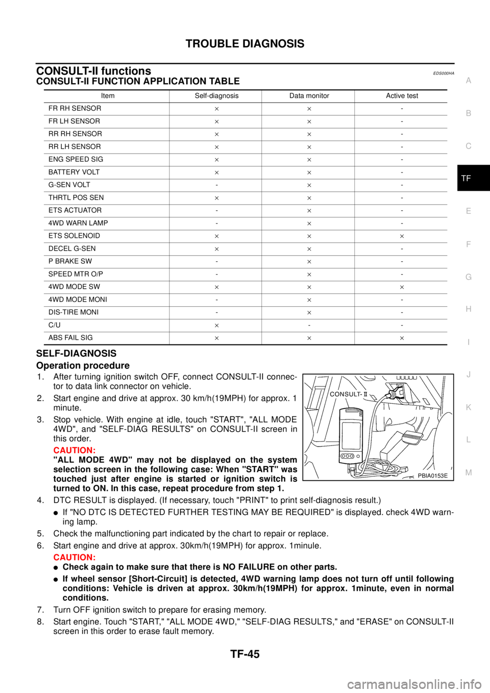
1. After turning ignition switch OFF, connect CONSULT-II connec-
tor to data link connector on vehicle.
2. Start engine and drive at approx. 30 km/h(19MPH) for approx. 1
minute.
3. Stop vehicle. With engine at idle, touch "START", "ALL MODE
4WD", and "SELF-DIAG RESULTS" on CONSULT-II screen in
this order.
CAUTION:
"ALL MODE 4WD" may not be displayed on the system
selection screen in the following case: When "START" was
touched just after engine is started or ignition switch is
turned to ON. In this case, repeat procedure from step 1.
4. DTC RESULT is displayed. (If necessary, touch "PRINT" to print self-diagnosis result.)
lIf "NO DTC IS DETECTED FURTHER TESTING MAY BE REQUIRED" is displayed. check 4WD warn-
ing lamp.
5. Check the malfunctioning part indicated by the chart to repair or replace.
6. Start engine and drive at approx. 30km/h(19MPH) for approx. 1minule.
CAUTION:
lCheck again to make sure that there is NO FAILURE on other parts.
lIf wheel sensor [Short-Circuit] is detected, 4WD warning lamp does not turn off until following
conditions: Vehicle is driven at approx. 30km/h(19MPH) for approx. 1minute, even in normal
conditions.
7. Turn OFF ignition switch to prepare for erasing memory.
8. Start engine. Touch "START," "ALL MODE 4WD," "SELF-DIAG RESULTS," and "ERASE" on CONSULT-II
screen in this order to erase fault memory.
Item Self-diagnosis Data monitor Active test
FR RH SENSOR´´-
FR LH SENSOR´´-
RR RH SENSOR´´-
RR LH SENSOR´´-
ENG SPEED SIG´´-
BATTERY VOLT´´-
G-SEN VOLT -´-
THRTL POS SEN´´-
ETS ACTUATOR -´-
4WD WARN LAMP -´-
ETS SOLENOID´´´
DECEL G-SEN´´-
P BRAKE SW -´-
SPEED MTR O/P -´-
4WD MODE SW´´´
4WD MODE MONI -´-
DIS-TIRE MONI -´-
C/U´--
ABS FAIL SIG´´´
PBIA0153E
Page 3016 of 3066

TF-46
TROUBLE DIAGNOSIS
CAUTION:
If memory cannot be erased, proceed to 5.
9. Drive at approx. 30 km/h (19MPH) for approx. 1 minute. Be sure 4WD warning lamp is OFF.
Display item list
CAUTION:
lIf "ALL MODE 4WD" is not displayed on system selection screen, check the following: 4WD actua-
tor and control unit, data link connector harness, and No. of CONSULT-II program card
lWhen several systems including CAN communication system indicates troubles, perform trouble
diagnosis of the CAN communication primarily.
DATA MONITOR
lFor details of data monitor function, refer to CONSULT -II Operation Manual.
Operation procedure
1. Turn the ignition switch to OFF.
2. Connect CONSULT-II connector to data link connector on vehicle.
3. Turn ignition switch ON.
4. Touch "START" on the display.
5. Touch "ALL MODE 4WD" on the display.
CAUTION:
"ALL MODE 4WD" may not be displayed on the system selection screen in the following case:
When "START" was touched just after engine is started or ignition switch is turned to ON. In this
case, repeat procedure from step 2.
6. Touch "DATA MONITOR".
7. Return to monitor item selection screen. Touch any of "ECU INPUT SIGNALS," "MAIN SIGNALS," "CAN
DIG SUPPORT MNTR" or "SELECTION FROM MENU".
Refer to the following "Data monitor item chart".
Item Malfunction detecting condition Check harness
DECEL G-SENSOR Longitudinal G-sensor output voltage is outside specification.
G-sensor harness
G-SENSOR VOLTAGEPower voltage of longitudinal G-sensor remains abnormally high
or low for a certain period of time.
ETS SOLENOID
(4WD solenoid valve) (Open)4WD solenoid valve control terminal is not supplied with proper
voltage due to open circuit in 4WD solenoid valve.
4WD actuator relay,
solenoid and harness ETS SOLENOID
(4WD solenoid valve) (Short)4WD solenoid valve control terminal is not supplied with proper
voltage due to short circuit in 4WD solenoid valve.
ETS SOLENOID
(4WD solenoid valve)
(CURRENT FAILURE)Current supplied to 4WD solenoid valve is abnormally high or
low compared with the specification.
CONTROL UNIT Processing function of 4WD control unit is malfunctioning.4WD control unit, power
and ground circuits
DECEL G-SEN MONI Output voltage of longitudinal G-sensor is outside specification. G-sensor harness
DECEL G-SEN IN Input voltage of longitudinal G-sensor is outside specification. G-sensor harness
3 V POWER SUPLY CHECK 4WD control unit internal 3V power supply is malfunctioning.Control unit power sup-
ply circuit
4WD A/R CHECK 4WD actuator relay turned on while it is controlled OFF.
4WD actuator relay,
4WD solenoid and har-
ness. 4WD SOL/V CHECK4WD solenoid not supplied with proper voltage
due to open circuit in 4WD solenoid valve.
CAN COMM
lCAN communication function of 4WD control unit is malfunc-
tioning.
lCAN communication function of EPS control unit is malfunc-
tioning.Control unit power sup-
ply circuit
ABS 4WD COMMWheel speed sensor system of ESP/TCS/ABS control unit is
malfunctioning.ESP/TCS/ABS control
unit and harness
Page 3017 of 3066

TROUBLE DIAGNOSIS
TF-47
C
E
F
G
H
I
J
K
L
MA
B
TF
8. Touch "MONITOR START".
9. Screen of data monitor is displayed.
Display item list
Item (Unit)Monitor item selection
Remarks
ECU INPUT SIG-
NALSMAIN
SIGNALSCAN DIAG SUP-
PORT MNTRSELECTION
FROM MENU
ENG SPEED SIG (STOP/
RUN)´´-´Condition of engine
(STOP/RUN) is dis-
played.
BATTERY VOLT (V)´--´Indicates voltage sup-
plied by 4WD control
unit
G-SEN VOLT (V)´--´G-sensor power sup-
ply condition (ON/OFF)
THRTL POS SEN (V)´´-´Indicates throttle posi-
tion sensor signal volt-
age
ETS ACTUATOR (ON-OFF) -´-´4WD actuator relay
ON/OFF condition
4WD WARNING LAMP
(ON-OFF)-´-´Indicates 4WD warn-
ing lamp operating con-
dition
ETS SOLENOID (A) -´-´Current supplied to
4WD solenoid valve
DECEL G-SEN (G)´´-´G-sensor operating
condition
4WD MODE SW
(AUTO, LOCK, 2WD)-´-´4WD mode recognized
by control unit
4WD MODE MONI
(AUTO, LOCK, 2WD)-´-´Output condition of
4WD mode indicator
lamp signal
DIS-TIRE MONITOR (mm) -´-´Improper size tire
installed condition
PBRAKESW(ON/OFF) -´-´Indicates parking brake
switch ON/OFF condi-
tion
SPEED MTR (O/P) (km/h) -´-´Indicates vehicle speed
recognized by meter
control unit
CAN EFFECT (OK-NG) -´-´CAN communication
signal (OK/NG) condi-
tion is displayed.
TCS FAIL SIG (ON-OFF) - - -´TCS fail signal condi-
tion is displayed (ON-
OFF)
EBD FAIL SIG (ON-OFF) - - -´EBD fail signal condi-
tion is displayed (ON-
OFF)
ABS FAIL SIG (ON-OFF) -´-´ABS operation (ON-
OFF) condition is dis-
played.
CAN COMM (OK-NG) - -´-CAN communication
signal (OK/NG) condi-
tion is displayed.
Page 3018 of 3066
TF-48
TROUBLE DIAGNOSIS
*:In case that the output signal from ESP/TCS/ABS control unit malfunction in wheel speed system.
ACTIVE TEST
CAUTION:
lDo not perform active test while driving.
lActive test cannot be performed with 4WD warning lamp on.
Operation procedure
1. Connect CONSULT-II to data link connector and start engine.
2. Touch "START" on the display.
3. Touch "ALL MODE 4WD".
4. Touch "ACTIVE TEST".
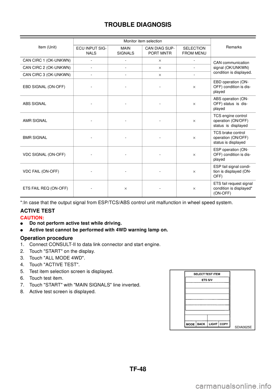
5. Test item selection screen is displayed.
6. Touch test item.
7. Touch "START" with "MAIN SIGNALS" line inverted.
8. Active test screen is displayed.
CANCIRC1(OK-UNKWN) - -´-
CAN communication
signal (OK/UNKWN)
condition is displayed. CANCIRC2(OK-UNKWN) - -´-
CANCIRC3(OK-UNKWN) - -´-
EBD SIGNAL (ON-OFF) - - -´EBD operation (ON-
OFF) condition is dis-
played
ABSSIGNAL ---´ABS operation (ON-
OFF) status is dis-
played
AMRSIGNAL ---´TCS engine control
operation (ON/OFF)
status is displayed
BMRSIGNAL ---´TCS brake control
operation (ON/OFF)
status is displayed
VDC SIGNAL (ON-OFF) - - -´ESP operation (ON-
OFF) condition is dis-
played
VDCFAIL(ON-OFF)---´ESP fail signal condi-
tion is displayed (ON-
OFF)
ETS FAIL REQ (ON-OFF) -´-´ETS fail request signal
condition is displayed*
(ON-OFF) Item (Unit)Monitor item selection
Remarks
ECU INPUT SIG-
NALSMAIN
SIGNALSCAN DIAG SUP-
PORT MNTRSELECTION
FROM MENU
SDIA0625E
Page 3021 of 3066
TROUBLE DIAGNOSIS
TF-51
C
E
F
G
H
I
J
K
L
MA
B
TF
4.G-SENSOR HARNESS INSPECTION
1. Disconnect G-sensor connector.
2. Disconnect control unit connector.
3. Check harness between control unit and G-sensor.
OK or NG
OK >> GO TO 5.
NG >> Repair or replace the harness.
5.G-SENSOR CIRCUIT CONNECTOR INSPECTION
Check the G-sensor and the control unit harness connector (including intermediate connector).
OK or NG
OK >> Perform the following.
1. Connect the connector and perform self-diagnosis again.
2. Be sure to drive the vehicle at 30km/h (19MPH) for 1minutes or longer and be sure that the
4WD warning lamp does not come on.
NG >> Repair or replace the connector.
4WD SOLENOID, ACTUATOR RELAY SYSTEM
Checking procedure
1.INSPECTION START
Use CONSULT-II and perform self-diagnosis.
OK or NG
OK >> Drive at 30 km/h (19MPH) for at least 1 minute. Check that 4WD warning lamp does not turn ON.
NG >> GO TO 2.
2.CONNECTOR INSPECTION
1. Disconnect the 4WD control unit connector and the 4WD solenoid connector. Check that terminals are not
deformed. Check that the connectors were connected properly. Reconnect connectors.
2. Perform self-diagnosis again.
OK or NG
OK >> Diagnosis completed.
NG >> GO TO 3.
3.INSPECTION OF 4WD SOLENOID UNIT
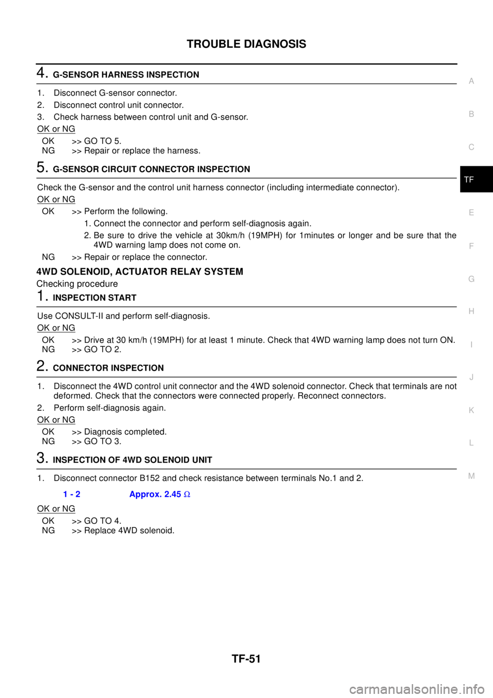
1. Disconnect connector B152 and check resistance between terminals No.1 and 2.
OK or NG
OK >> GO TO 4.
NG >> Replace 4WD solenoid.1 - 2 Approx. 2.45W
Page 3022 of 3066
TF-52
TROUBLE DIAGNOSIS
4.INSPECTION OF 4WD SOLENOID CIRCUIT HARNESS
1. Disconnect the 4WD solenoid connector.
2. Disconnect the 4WD control unit.
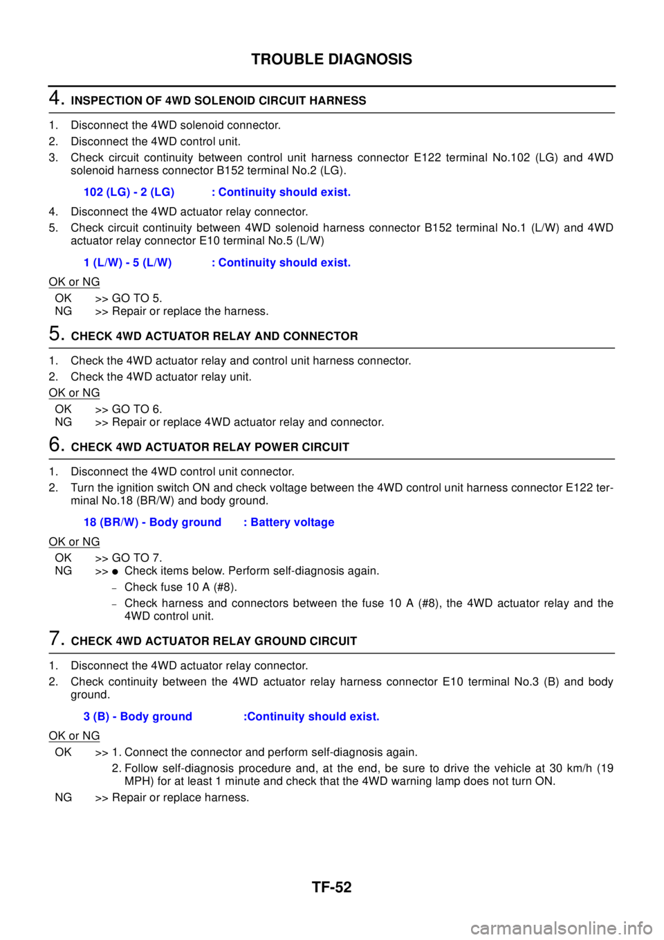
3. Check circuit continuity between control unit harness connector E122 terminal No.102 (LG) and 4WD
solenoid harness connector B152 terminal No.2 (LG).
4. Disconnect the 4WD actuator relay connector.
5. Check circuit continuity between 4WD solenoid harness connector B152 terminal No.1 (L/W) and 4WD
actuator relay connector E10 terminal No.5 (L/W)
OK or NG
OK >> GO TO 5.
NG >> Repair or replace the harness.
5.CHECK 4WD ACTUATOR RELAY AND CONNECTOR
1. Check the 4WD actuator relay and control unit harness connector.
2. Check the 4WD actuator relay unit.
OK or NG
OK >> GO TO 6.
NG >> Repair or replace 4WD actuator relay and connector.
6.CHECK 4WD ACTUATOR RELAY POWER CIRCUIT
1. Disconnect the 4WD control unit connector.
2. Turn the ignition switch ON and check voltage between the 4WD control unit harness connector E122 ter-
minal No.18 (BR/W) and body ground.
OK or NG
OK >> GO TO 7.
NG >>
lCheck items below. Perform self-diagnosis again.
–Check fuse 10 A (#8).
–Check harness and connectors between the fuse 10 A (#8), the 4WD actuator relay and the
4WD control unit.
7.CHECK 4WD ACTUATOR RELAY GROUND CIRCUIT
1. Disconnect the 4WD actuator relay connector.
2. Check continuity between the 4WD actuator relay harness connector E10 terminal No.3 (B) and body
ground.
OK or NG
OK >> 1. Connect the connector and perform self-diagnosis again.
2. Follow self-diagnosis procedure and, at the end, be sure to drive the vehicle at 30 km/h (19
MPH) for at least 1 minute and check that the 4WD warning lamp does not turn ON.
NG >> Repair or replace harness.102 (LG) - 2 (LG) : Continuity should exist.
1 (L/W) - 5 (L/W) : Continuity should exist.
18 (BR/W) - Body ground : Battery voltage
3 (B) - Body ground :Continuity should exist.
Page 3025 of 3066
TROUBLE DIAGNOSIS
TF-55
C
E
F
G
H
I
J
K
L
MA
B
TF
3.CHECK COMBINATION METER POWER CIRCUIT
1. Disconnect combination meter connector.
2. With ignition ON, check the voltage between the combination meter harness connector M44 terminal
No.46 (W/L) (LHD models) or No.59 (W/L) (RHD models) and body ground.
OK or NG
OK >> GO TO 4.
NG >> Check combination meter circuits.
4.CHECK 4WD AUTO LAMP (ON COMBINATION METER) CIRCUIT
Check continuity between combination meter terminal 46 (LHD models) or 59 (RHD models) and terminal 18.
OK or NG
OK >> Using CONSULT-II perform self-diagnosis.
NG >> Check for burned-out bulb in 4WD AUTO lamp.
4WD WARNING LAMP DOES NOT ILLUMINATE WITH IGNITION ON
1.INSPECTION OF BLOWN FUSE BETWEEN IGNITION SWITCH AND COMBINATION METER
Check blown fuse between ignition switch and combination meter.
OK or NG
OK >> GO TO 2 (No blown fuse)
NG >> Replace the fuse and perform the inspection again.
2.COMBINATION METER POWER SUPPLY CIRCUIT INSPECTION
1. Disconnect combination meter connector.
2. Check voltage between the combination meter harness connector M46 terminal No. LHD models: 46 (W/
L) RHD models: 59 (W/L) and body ground.
OK or NG
OK >> Malfunctioning combination meter.
NG >> Check fuse 10A [#11] to combination meter harness and connector.
4WD WARNING LAMP DOES NOT GO OUT SEVERAL SECONDS AFTER ENGINE
STARTED.(4WD MODE INDICATOR LAMP GOES OUT)
1.PERFORM SELF-DIAGNOSIS
Using CONSULT-II perform self-diagnosis.
OK or NG
OK >> No malfunction detected. Perform inspection again.
NG >>
lDetermine the location of the malfunction according to the result of Self-diagnosis using CON-
SULT-II. (Malfunction is present in the 4WD system.)
lCONSULT-II does not display 4WD system-related trouble codes. GO TO 2. LHD models:46 (W/L), RHD models: 59(W/L) 1(W)
- Body ground
: Battery voltage
46 (LHD models) or 59 (RHD models) - 18
: Continuity should exist.