2003 NISSAN X-TRAIL warning
[x] Cancel search: warningPage 2943 of 3066

TROUBLE DIAGNOSIS
SRS-21
C
D
E
F
G
I
J
K
L
MA
B
SRS
Diagnostic code chart
Diagnostic item ExplanationRepair order
“Recheck SRS at each replacement”
NO DTC IS
DETECTED.When malfunction is
indicated by the “AIR
BAG” warning lamp in
User mode.
lLow battery voltage (Less than 9V)lGo toSRS-20, "DIAGNOSTIC PRO-
CEDURE 3".
lSelf-diagnostic result “SELF-DIAG
[PAST]” (previously stored in the
memory) might not be erased after
repair.
lIntermittent malfunction has been
detected in the past.
lGo toSRS-17, "DIAGNOSTIC PRO-
CEDURE 2".
lNo malfunction is detected. —
DRIVER AIRBAG
MODULE
[OPEN]
lDriver air bag module circuit is open (including the spiral cable). 1. Visually check the wiring harness
connection.
2. Replace the harness if it has visible
damage.
3. Replace driver air bag module.
(Before disposal, it must be
deployed.)
4. Replace the spiral cable.
5. Replace the diagnosis sensor unit.
6. Replace the related harness. DRIVER AIRBAG
MODULE
[VB-SHORT]
lDriver air bag module circuit is shorted to some power supply
circuit (including the spiral cable).
DRIVER AIRBAG
MODULE
[GND-SHORT]
lDriver air bag module circuit is shorted to ground (including the
spiral cable).
DRIVER AIRBAG
MODULE
[SHORT]
lDriver air bag module circuits are shorted to each other.
ASSIST A/B MODULE
[VB-SHORT]
lFront passenger air bag module circuit is shorted to some
power supply circuit.1. Visually check the wiring harness
connection.
2. Replace the harness if it has visible
damage.
3. Replace front passenger air bag
module. (Before disposal of it, it
must be deployed.)
4. Replace the diagnosis sensor unit.
5. Replace the related harness. ASSIST A/B MODULE
[OPEN]
lFront passenger air bag module circuit is open.
ASSIST A/B MODULE
[GND-SHORT]
lFront passenger air bag module circuit is shorted to ground.
ASSIST A/B MODULE
[SHORT]
lFront passenger air bag module circuits are shorted to each
other.
SIDE MODULE LH
[OPEN]
lFront LH side air bag module circuit is open. 1. Visually check the wiring harness
connection.
2. Replace the harness if it has visible
damage.
3. Replace front LH side air bag mod-
ule.
(Before disposal, it must be
deployed.)
4. Replace the diagnosis sensor unit.
5. Replace the related harness. SIDE MODULE LH
[VB-SHORT]
lFront LH side air bag module circuit is shorted to some power
supply circuit.
SIDE MODULE LH
[GND-SHORT]
lFront LH side air bag module circuit is shorted to ground.
SIDE MODULE LH
[SHORT]
lFront LH side air bag module circuits are shorted to each other.
SIDE MODULE RH
[OPEN]
lFront RH side air bag module circuit is open. 1. Visually check the wiring harness
connection.
2. Replace the harness if it has visible
damage.
3. Replace front RH side air bag mod-
ule.
(Before disposal, it must be
deployed.)
4. Replace the diagnosis sensor unit.
5. Replace the related harness. SIDE MODULE RH
[VB-SHORT]
lFront RH side air bag module circuit is shorted to some power
supply circuit.
SIDE MODULE RH
[GND-SHORT]
lFront RH side air bag module circuit is shorted to ground.
SIDE MODULE RH
[SHORT]
lFront RH side air bag module circuits are shorted to each other.
Page 2944 of 3066

SRS-22
TROUBLE DIAGNOSIS
NOTE:
lFollow the procedures in numerical order when repairing malfunctioning parts. Confirm whether malfunction is eliminated using air
bag warning lamp or CONSULT-II each time repair is finished. If malfunction is still observed, proceed to the next step. When mal-
function is eliminated, further repair work is not required.
lFollow the procedures in numerical order when repairing malfunctioning parts, then make the system check.
lThe screen contents are the same as the self-diagnosis results, self-diagnosis results “SELF-DIAG [CURRENT]” and “SELF-DIAG
[PAST]”.
Trouble Diagnoses Without CONSULT-IIEHS000CT
DIAGNOSTIC PROCEDURE 5
CAUTION:
SRS will not enter diagnosis mode if no malfunction is detected in user mode.
1. Turn ignition switch “ON”.
SATELLITE SENS LH
[UNIT FAIL]
SATELLITE SENS LH
[COMM FAIL]
SATELLITE SENS LH
[UNMATCH]lLH side air bag (Satellite) sensor 1. Visually check the wiring harness
connection.
2. Replace the harness if it has visible
damage.
3. Replace the LH side air bag (satel-
lite) sensor.
4. Replace the diagnosis sensor unit.
5. Replace the related harness.
SATELLITE SENS RH
[UNIT FAIL]
SATELLITE SENS RH
[COMM FAIL]
SATELLITE SENS RH
[UNMATCH]
lRH side air bag (Satellite) sensor 1. Visually check the wiring harness
connection.
2. Replace the harness if it has visible
damage.
3. Replace the RH side air bag (satel-
lite) sensor.
4. Replace the diagnosis sensor unit.
5. Replace the related harness.
PRE-TEN FRONT LH
[OPEN]
lThe circuit for front LH pre-tensioner is open.
1. Visually check the wiring harness
connections.
2. Replace the harness if it has visible
damage.
3. Replace front LH seat belt.
(Before disposing, it must be deacti-
vated.)
4. Replace the diagnosis sensor unit.
5. Replace the related harness. PRE-TEN FRONT LH
[VB-SHORT]
lThe circuit for front LH pre-tensioner is shorted to some power
supply circuit.
PRE-TEN FRONT LH
[GND-SHORT]
lThe circuit for front LH pre-tensioner is shorted to ground.
PRE-TEN FRONT RH
[OPEN]
lThe circuit for front RH pre-tensioner is shorted to some power
supply circuit.
1. Visually check the wiring harness
connections.
2. Replace the harness if it has visible
damage.
3. Replace front RH seat belt.
(Before disposing, it must be deacti-
vated.)
4. Replace the diagnosis sensor unit.
5. Replace the related harness. PRE-TEN FRONT RH
[VB-SHORT]
lThe circuit for front RH pre-tensioner is shorted to some power
supply circuit.
PRE-TEN FRONT RH
[GND-SHORT]
lThe circuit for front RH pre-tensioner is shorted to ground.
CONTROL UNIT
lDiagnosis sensor unit is malfunctioning. 1. Visually check the wiring harness
connection.
2. Replace the diagnosis sensor unit. Diagnostic item ExplanationRepair order
“Recheck SRS at each replacement”
Page 2945 of 3066
TROUBLE DIAGNOSIS
SRS-23
C
D
E
F
G
I
J
K
L
MA
B
SRS
2. After “AIR BAG” warning lamp lights for 7seconds, turn ignition switch “OFF” within 1seconds.
3. Wait more than 3 seconds.
4. Repeat the steps 1 to 2 two times.
5. Turn ignition switch ON”.
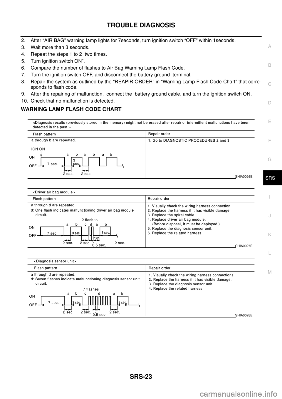
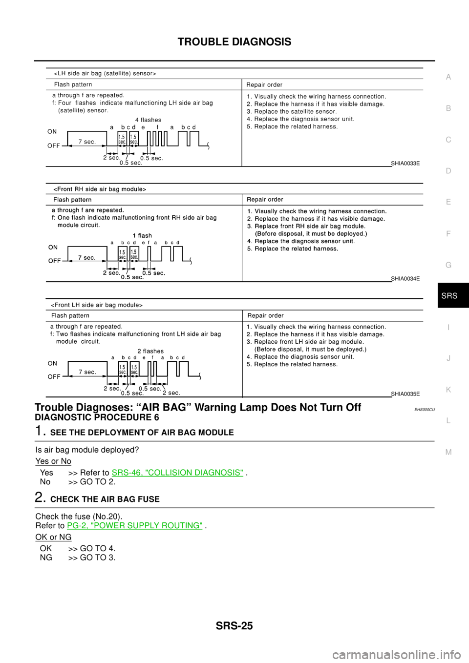
6. Compare the number of flashes to Air Bag Warning Lamp Flash Code.
7. Turn the ignition switch OFF, and disconnect the battery ground terminal.
8. Repair the system as outlined by the “REAPIR ORDER” in “Warning Lamp Flash Code Chart” that corre-
sponds to flash code.
9. After the repairing of malfunction, connect the battery ground cable, and turn the ignition switch ON.
10. Check that no malfunction is detected.
WARNING LAMP FLASH CODE CHART
SHIA0026E
SHIA0027E
SHIA0028E
Page 2947 of 3066
TROUBLE DIAGNOSIS
SRS-25
C
D
E
F
G
I
J
K
L
MA
B
SRS
Trouble Diagnoses: “AIR BAG” Warning Lamp Does Not Turn OffEHS000CU
DIAGNOSTIC PROCEDURE 6
1.SEE THE DEPLOYMENT OF AIR BAG MODULE
Is air bag module deployed?
Ye s o r N o
Yes >> Refer toSRS-46, "COLLISION DIAGNOSIS".
No >> GO TO 2.
2.CHECK THE AIR BAG FUSE
Check the fuse (No.20).
Refer toPG-2, "
POWER SUPPLY ROUTING".
OK or NG
OK >> GO TO 4.
NG >> GO TO 3.
SHIA0033E
SHIA0034E
SHIA0035E
Page 2948 of 3066
SRS-26
TROUBLE DIAGNOSIS
3.CHECK AIR BAG FUSE AGAIN
Replace “AIR BAG” fuse and turn ignition switch ON.
Is
“AIR BAG”fuse blown again?
Yes >> Repair main harness.
No >>INSPECTION END
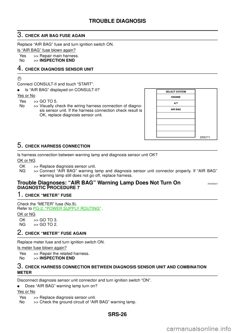
4.CHECK DIAGNOSIS SENSOR UNIT
Connect CONSULT-II and touch “START”.
lIs “AIR BAG” displayed on CONSULT-II?
Ye s o r N o
Yes >>GOTO5.
No >> Visually check the wiring harness connection of diagno-
sis sensor unit. If the harness connection check result is
OK, replace diagnosis sensor unit.
5.CHECK HARNESS CONNECTION
Is harness connection between warning lamp and diagnosis sensor unit OK?
OK or NG
OK >> Replace diagnosis sensor unit.
NG >> Connect “AIR BAG” warning lamp and diagnosis sensor unit connector properly. If “AIR BAG”
warning lamp still does not go off, replace harness.
Trouble Diagnoses: “AIR BAG” Warning Lamp Does Not Turn OnEHS000CV
DIAGNOSTIC PROCEDURE 7
1.CHECK “METER” FUSE
Check the “METER” fuse (No.9).
Refer toPG-2, "
POWER SUPPLY ROUTING".
OK or NG
OK >> GO TO 3.
NG >> GO TO 2.
2.CHECK “METER” FUSE AGAIN
Replace meter fuse and turn ignition switch ON.
Is meter fuse blown again?
Yes >> Repair the related harness.
No >>INSPECTION END
3.CHECK HARNESS CONNECTION BETWEEN DIAGNOSIS SENSOR UNIT AND COMBINATION
METER
Disconnect diagnosis sensor unit connector and turn ignition switch “ON”.
lDoes “AIR BAG” warning lamp turn on?
Ye s o r N o
Yes >> Replace diagnosis sensor unit.
No >> Check the ground circuit of “AIR BAG” warning lamp.
SRS771
Page 2968 of 3066
SRS-46
COLLISION DIAGNOSIS
COLLISION DIAGNOSIS
PFP:00015
For Frontal CollisionEHS000DF
To repair the SRS, perform the following steps.
WHEN SRS (EXCEPT THE FRONT SIDE AIR BAG ) IS ACTIVED IN A COLLISION :
1. Replace the diagnosis sensor unit.
2. Remove the air bag modules (except the front side air bag module), bracket and seat belt pre-tensioner
assemblies.
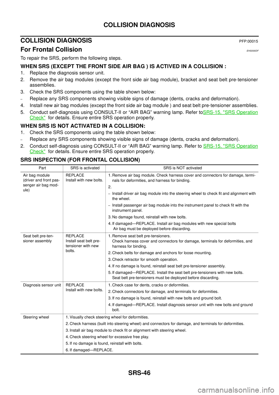
3. Check the SRS components using the table shown below:
–Replace any SRS components showing visible signs of damage (dents, cracks and deformation).
4. Install new air bag modules (except the front side air bag module ) and seat belt pre-tensioner assemblies.
5. Conduct self-diagnosis using CONSULT-II or “AIR BAG” warning lamp. Refer toSRS-15, "
SRS Operation
Check"for details. Ensure entire SRS operation properly.
WHEN SRS IS NOT ACTIVATED IN A COLLISION:
1. Check the SRS components using the table shown below:
–Replace any SRS components showing visible signs of damage (dents, cracks and deformation).
2. Conduct self-diagnosis using CONSULT-II or “AIR BAG” warning lamp. Refer toSRS-15, "
SRS Operation
Check"for details. Ensure entire SRS operation properly.
SRS INSPECTION (FOR FRONTAL COLLISION)
Part SRS is activated SRS is NOT activated
Air bag module
(driver and front pas-
senger air bag mod-
ule)REPLACE
Install with new bolts.1. Remove air bag module. Check harness cover and connectors for damage, termi-
nals for deformities, and harness for binding.
2.
–Install driver air bag module into the steering wheel to check fit and alignment with
the wheel.
–Install passenger air bag module into the instrument panel to check fit with the
instrument panel.
3. No damage found, reinstall with new bolts.
4. If damaged—REPLACE. Install air bag modules with new special bolts
Air bag must be deployed before discarding.
Seat belt pre-ten-
sioner assemblyREPLACE
Install seat belt pre-
tensioner with new
bolts.1. Remove seat belt pre-tensioners.
Check harness cover and connectors for damage, terminals for deformities, and
harness for binding.
2. Check belts for damage and anchors for loose mounting.
3. Check retractor for smooth operation.
4. If no damage is found, reinstall seat belt pre-tensioner assembly.
5. If damaged—REPLACE. Install the seat belt pre-tensioners with new bolts.
Seat belt pre-tensioners must be deployed before discarding.
Diagnosis sensor unit REPLACE
Install with new bolts.1. Check case for dents, cracks or deformities.
2. Check connectors for damage, and terminals for deformities.
3. If no damage is found, reinstall with new bolts and ground bolt.
4. If damaged—REPLACE. Install diagnosis sensor unit with new bolts and ground
bolt.
Steering wheel 1. Visually check steering wheel for deformities.
2. Check harness (built into steering wheel) and connectors for damage, and terminals for deformities.
3. Install air bag module to check fit or alignment with steering wheel.
4. Check steering wheel for excessive free play.
5. If no damage is found, reinstall with bolts.
6. If damaged—REPLACE.
Page 2969 of 3066
COLLISION DIAGNOSIS
SRS-47
C
D
E
F
G
I
J
K
L
MA
B
SRS
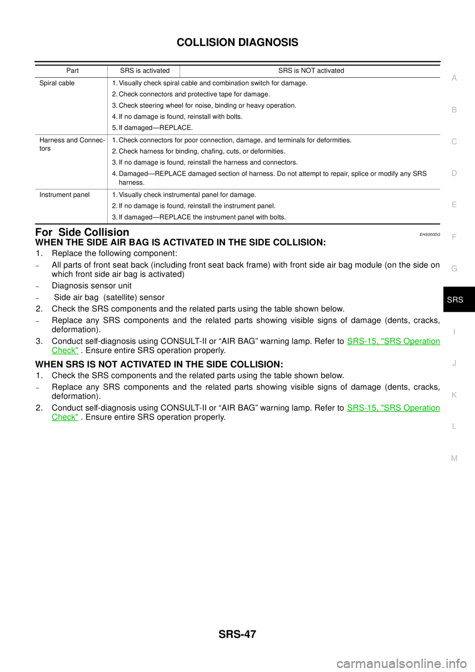
For Side CollisionEHS000DG
WHENTHESIDEAIRBAGISACTIVATEDINTHESIDECOLLISION:
1. Replace the following component:
–All parts of front seat back (including front seat back frame) with front side air bag module (on the side on
which front side air bag is activated)
–Diagnosis sensor unit
–Side air bag (satellite) sensor
2. Check the SRS components and the related parts using the table shown below.
–Replace any SRS components and the related parts showing visible signs of damage (dents, cracks,
deformation).
3. Conduct self-diagnosis using CONSULT-II or “AIR BAG” warning lamp. Refer toSRS-15, "
SRS Operation
Check". Ensure entire SRS operation properly.
WHEN SRS IS NOT ACTIVATED IN THE SIDE COLLISION:
1. Check the SRS components and the related parts using the table shown below.
–Replace any SRS components and the related parts showing visible signs of damage (dents, cracks,
deformation).
2. Conduct self-diagnosis using CONSULT-II or “AIR BAG” warning lamp. Refer toSRS-15, "
SRS Operation
Check". Ensure entire SRS operation properly.
Spiral cable 1. Visually check spiral cable and combination switch for damage.
2. Check connectors and protective tape for damage.
3. Check steering wheel for noise, binding or heavy operation.
4. If no damage is found, reinstall with bolts.
5. If damaged—REPLACE.
Harness and Connec-
tors1. Check connectors for poor connection, damage, and terminals for deformities.
2. Check harness for binding, chafing, cuts, or deformities.
3. If no damage is found, reinstall the harness and connectors.
4. Damaged—REPLACE damaged section of harness. Do not attempt to repair, splice or modify any SRS
harness.
Instrument panel 1. Visually check instrumental panel for damage.
2. If no damage is found, reinstall the instrument panel.
3. If damaged—REPLACE the instrument panel with bolts. Part SRS is activated SRS is NOT activated
Page 2971 of 3066

TF-1
TRANSFER
D DRIVELINE/AXLE
CONTENTS
C
E
F
G
H
I
J
K
L
M
SECTION
A
B
TF
TRANSFER
PRECAUTIONS .......................................................... 3
Caution ..................................................................... 3
PREPARATION ........................................................... 4
Special Service Tools ............................................... 4
NOISE, VIBRATION, AND HARSHNESS (NVH)
TROUBLESHOOTING ................................................ 7
NVH Troubleshooting Chart ..................................... 7
TRANSFER FLUID ..................................................... 8
Replacement ............................................................ 8
DRAINING ............................................................. 8
FILLING ................................................................. 8
Inspection ................................................................. 8
OIL LEAKAGE AND OIL LEVEL ........................... 8
SIDE OIL SEAL .......................................................... 9
Removal and Installation .......................................... 9
REMOVAL ............................................................. 9
INSTALLATION ..................................................... 9
AIR BREATHER HOSE ............................................ 10
Removal and Installation ........................................ 10
TRANSFER ASSEMBLY .......................................... 12
Removal and Installation from Vehicle ................... 12
REMOVAL ........................................................... 12
INSTALLATION ................................................... 12
Component Parts Drawing ..................................... 14
Assembly Inspection .............................................. 15
BACKLASH ......................................................... 15
TOOTH CONTACT .............................................. 15
PRELOAD TORQUE ........................................... 17
COMPANION FLANGE RUNOUT ...................... 18
Disassembly and Assembly ................................... 19
DISASSEMBLY ................................................... 19
INSPECTION AFTER DISASSEMBLY ............... 23
SELECTIONG ADJUSTING SHIMS ................... 24
ASSMBLY ........................................................... 26
ALL MODE 4X4 SYSTEM ........................................ 31
Precautions ............................................................ 31
System Component ................................................ 31
System Description ................................................ 31
ERECTRONIC COUPLING ................................. 31
4WD CONTROL UNIT ........................................ 314WD MODE SWITCT .......................................... 32
4WD WARNING LAMP ....................................... 32
FAIL- SAFE FUNCTION ...................................... 33
System Diagram ..................................................... 33
CAN Communication .............................................. 33
SYSTEM DESCRIPTION .................................... 33
SYSTEM DIAGRAM ............................................ 33
INPUT/OUTPUT SIGNAL .................................... 34
Circuit Diagram ....................................................... 35
Wiring Diagram ....................................................... 36
TROUBLE DIAGNOSIS ............................................ 40
Fail-safe function .................................................... 40
How to proceed with trouble diagnosis ................... 40
BASIC CONCEPT ............................................... 40
Trouble diagnosis chart by symptom ...................... 41
4WD control unit input/output signal standard ........ 42
4WD CONTROL UNIT CONNECTOR TERMI-
NAL ARRANGEMENT ........................................ 42
REFERENCE STANDARD TABLE ...................... 43
CONSULT-II functions ............................................ 45
CONSULT-II FUNCTION APPLICATION TABLE... 45
SELF-DIAGNOSIS .............................................. 45
DATA MONITOR ................................................. 46
ACTIVE TEST ..................................................... 48
ECU PART NUMBER .......................................... 49
Component Inspection ............................................ 49
4WD SOLENOID VALVE ..................................... 49
System Inspection .................................................. 49
CONTROL UNIT POWER SUPPLY SYSTEM .... 49
G-SENSOR SYSTEM ......................................... 50
4WD SOLENOID, ACTUATOR RELAY SYSTEM... 51
CAN COMMUNICATION SYSTEM ..................... 53
4WD MODE SWITCH SYSTEM .......................... 53
Trouble Diagnoses for Symptoms .......................... 54
4WD INDICATOR LAMP DOSE NOT COME ON
FORAPPROXIMATELY1SECONDWHENTHE
IGNITION SWITCH IS TURNED TO ON ............. 54
4WD WARNING LAMP DOES NOT ILLUMINATE
WITH IGNITION ON ............................................ 55
4WD WARNING LAMP DOES NOT GO OUT