2003 NISSAN X-TRAIL warning
[x] Cancel search: warningPage 982 of 3066
![NISSAN X-TRAIL 2003 Electronic Repair Manual BRC-114
[ESP/TCS/ABS]
TROUBLE DIAGNOSIS
4.WHEEL SPEED SENSOR INSPECTION
Check the wheel speed sensor system.
lSensor mounting inspection
lSensor pick-up inspection for iron chips
lSensor rotor inspect NISSAN X-TRAIL 2003 Electronic Repair Manual BRC-114
[ESP/TCS/ABS]
TROUBLE DIAGNOSIS
4.WHEEL SPEED SENSOR INSPECTION
Check the wheel speed sensor system.
lSensor mounting inspection
lSensor pick-up inspection for iron chips
lSensor rotor inspect](/manual-img/5/57402/w960_57402-981.png)
BRC-114
[ESP/TCS/ABS]
TROUBLE DIAGNOSIS
4.WHEEL SPEED SENSOR INSPECTION
Check the wheel speed sensor system.
lSensor mounting inspection
lSensor pick-up inspection for iron chips
lSensor rotor inspection (e.g. Number of teeth, damaged teeth)
lSensor connector engagement inspection
Is inspection result OK?
YES >> Normal
NO >> Wheel speed sensor and rotor lines repair
Symptom 4: ABS Does Not Work.EF S0 01 AV
Inspection procedure
1.ABS WARNING LAMP INDICATOR INSPECTION
Check that the ABS warning lamp illuminates.
Does the ABS warning lamp illuminate?
YES >> Perform the self-diagnosis.
NO >> GO TO 2.
2.WHEEL SPEED SENSOR INSPECTION
Check the wheel speed sensor system.
lSensor mounting inspection
lSensor pick-up inspection for iron chips
lSensor rotor inspection (e.g. Number of teeth, damaged teeth)
lSensor connector engagement inspection
Is inspection result OK?
YES >> Normal
NO >> Wheel speed sensor and rotor lines repair
Symptom 5: Pedal Vibration and NoiseEFS001AW
Inspection procedure
1.SYMPTOM CHECK
Check the brake system for pedal vibration or noise at the engine start.
Is inspection result OK?
YES >> Perform the self-diagnosis.
NO >> GO TO 2.
2.SYMPTOM CHECK 2
Check the brake system for pedal vibration or noise when the pedal depressed lightly (just put a foot on).
CAUTION:
Under the following driving conditions, the wheel speed will fluctuates, resulting in ABS activation.
lWhen shifting gears
lHigh speed cornering
lWhenagustofwind
Is inspection result OK?
YES >> GO TO 3.
NO >> Normal
Page 983 of 3066
![NISSAN X-TRAIL 2003 Electronic Repair Manual TROUBLE DIAGNOSIS
BRC-115
[ESP/TCS/ABS]
C
D
E
G
H
I
J
K
L
MA
B
BRC
3.SYMPTOM CHECK 3
Does the symptom appear during normal braking operation?
CAUTION:
ABS may work in following driving conditions even NISSAN X-TRAIL 2003 Electronic Repair Manual TROUBLE DIAGNOSIS
BRC-115
[ESP/TCS/ABS]
C
D
E
G
H
I
J
K
L
MA
B
BRC
3.SYMPTOM CHECK 3
Does the symptom appear during normal braking operation?
CAUTION:
ABS may work in following driving conditions even](/manual-img/5/57402/w960_57402-982.png)
TROUBLE DIAGNOSIS
BRC-115
[ESP/TCS/ABS]
C
D
E
G
H
I
J
K
L
MA
B
BRC
3.SYMPTOM CHECK 3
Does the symptom appear during normal braking operation?
CAUTION:
ABS may work in following driving conditions even if there is no sudden brake.
lWhen road friction is low.
lHigh speed cornering
lWhenagustofwind
Is inspection result OK?
YES >> GO TO 4.
NO >> Normal
4.SYMPTOM CHECK 4
Check that the symptom is reproduce when the engine speed is increased with the vehicle stopped.
Is inspection result OK?
YES >> GO TO 5.
NO >>
lNormal.
CAUTION:
This symptom may appear with vehicle stopped.
5.SYMPTOM CHECK 5
Check that the symptom is reproduce when any switch of electrical equipment is operated.
Is inspection result OK?
YES >> Check that there are no radio, antenna, and antenna lead-in wires (including wiring) near control
unit.
NO >> GO TO 6.
6.ABS WARNING LAMP INSPECTION
Check that the ABS warning lamp turns on.
Is inspection result OK?
YES >> Perform the self-diagnosis.
NO >> GO TO 7.
7.WHEEL SPEED SENSOR INSPECTION
Check the wheel speed sensor system.
lSensor mounting inspection
lSensor pick-up inspection for iron chips (e.g. Number of teeth, damaged teeth)
lSensor connector engagement inspection
lWheel speed sensor path harness and connector inspection
Is inspection result OK?
YES >> Normal
NO >> Wheel speed sensor and rotor lines repair
Symptom 6: ESP OFF Indicator Lamp Does Not IlluminateEFS001AX
Inspection procedure
1.ESP OFF INDICATOR LAMP INSPECTION
Disconnect the ESP/TCS/ABS control unit connector.
Does the ABS warning lamp and ESP OFF indicator lamp illuminate?
YES >> ESP/TCS/ABS control unit malfunction. Repair or replace the control unit.
NO >> Combination meter system malfunction. Check the combination meter.
Page 984 of 3066
![NISSAN X-TRAIL 2003 Electronic Repair Manual BRC-116
[ESP/TCS/ABS]
TROUBLE DIAGNOSIS
Symptom 7: SLIP Indicator Lamp Does Not Illuminate
EFS001AY
Inspection procedure
1.SLIP INDICATOR LAMP BURNED-OUT BULB INSPECTION
Check for continuity between t NISSAN X-TRAIL 2003 Electronic Repair Manual BRC-116
[ESP/TCS/ABS]
TROUBLE DIAGNOSIS
Symptom 7: SLIP Indicator Lamp Does Not Illuminate
EFS001AY
Inspection procedure
1.SLIP INDICATOR LAMP BURNED-OUT BULB INSPECTION
Check for continuity between t](/manual-img/5/57402/w960_57402-983.png)
BRC-116
[ESP/TCS/ABS]
TROUBLE DIAGNOSIS
Symptom 7: SLIP Indicator Lamp Does Not Illuminate
EFS001AY
Inspection procedure
1.SLIP INDICATOR LAMP BURNED-OUT BULB INSPECTION
Check for continuity between the power supply terminal of meter and terminal of ABS warning lamp.
Is inspection result OK?
OK >> GO TO 2.
NG >> Circuit malfunction in SLIP indicator lamp or combination meter
2.SLIP INDICATOR LAMP POWER CIRCUIT INSPECTION
Disconnect the meter connector. Check that the voltage between the vehicle-side harness terminal and body
ground is battery voltage (Approx. 12V).
Is inspection result OK?
YES >> GO TO 3.
NO >>
lFuse inspection
lInspection for harness and connectors between fuse block and meter
lCheck the power supply circuit (battery and ignition switch circuit).
3.SLIP INDICATOR LAMP HARNESS INSPECTION
1. Disconnect connectors for the ESP/TCS/ABS control unit and meter vehicle-side harness.
2. Check the harness between the meter and the ESP/TCS/ABS control unit for an open/shorted circuit.
Is inspection result OK?
OK >> GO TO 4.
NG >> Repair or replace the disconnected harness.
4.SLIP INDICATOR LAMP CONNECTOR INSPECTION
Check connectors for the ESP/TCS/ABS control unit and meter vehicle-side harness.
Is inspection result OK?
YES >> Connect connectors, and perform the self-diagnosis. The vehicle harness has the intermediate
connector. Refer to the vehicle wiring diagram, always check it.
NG >> Repair or replace the disconnected connector.
Symptom 8: During ESP/TCS/ABS Control, Vehicle Behavior is Jerky.EFS001AZ
Inspection procedure
1.ENGINE SPEED SIGNAL INSPECTION
Perform²DATA MONITOR²with CONSULT-II for the ESP/TCS/ABS control unit.
Is the engine speed at idle 400 rpm or higher?
YES >> Normal
NO >> GO TO 2.
2.SELF-DIAGNOSIS RESULT CHECK 1
Perform the ESP/TCS/ABS control unit self-diagnosis.
Is the self-diagnosis results displayed?
YES >> After checking and repairing the applicable item, perform the ESP/TCS/ABS control unit self-
diagnosis again.
NO >> GO TO 3.
Page 1055 of 3066

DI-1
DRIVER INFORMATION SYSTEM
K ELECTRICAL
CONTENTS
C
D
E
F
G
H
I
J
L
M
SECTION
A
B
DI
DRIVER INFORMATION SYSTEM
PRECAUTIONS .......................................................... 3
Precautions for Supplemental Restraint System
(SRS) “AIR BAG” and “SEAT BELT PRE-TEN-
SIONER” .................................................................. 3
Wiring Diagrams and Trouble Diagnosis .................. 3
COMBINATION METERS (LHD MODELS) ................ 4
System Description .................................................. 4
UNIFIED CONTROL METER ................................ 4
HOW TO CHANGE THE DISPLAY FOR ODO/
TRIP METER ........................................................ 4
POWER SUPPLY AND GROUND CIRCUIT ........ 4
WATER TEMPERATURE GAUGE ........................ 4
TACHOMETER ..................................................... 5
FUEL GAUGE ....................................................... 5
SPEEDOMETER ................................................... 5
Component Parts and Harness Connector Location..... 5
Combination Meter ................................................... 6
CHECK .................................................................. 6
Schematic ................................................................ 7
Wiring Diagram — METER — .................................. 8
Meter/Gauge Operation and Odo/Trip Meter Seg-
ment Check in Diagnosis Mode ............................. 10
DIAGNOSIS FUNCTION ..................................... 10
HOW TO ALTERNATE DIAGNOSIS MODE ....... 10
Trouble Diagnoses ................................................. 10
PRELIMINARY CHECK ...................................... 10
SYMPTOM CHART ..............................................11
Power Supply and Ground Circuit Check ............... 12
Inspection/Engine Speed Signal ............................ 12
Inspection/Water Temperature Gauge /Gasoline
Engine Models ....................................................... 13
Inspection/Water Temperature Gauge (Diesel
Engine Models) ...................................................... 13
Inspection/Vehicle speed signal ............................. 14
Inspection/Fuel Level Sensor Unit ......................... 15
FUEL LEVEL SENSOR UNIT ............................. 15
LOW-FUEL WARNING LAMP ............................. 15
The Fuel Gauge Pointer Fluctuates·Indicator
Wrong Value·or Varies. ........................................... 17
The Fuel Gauge Does Not Move to F-position. ...... 18The Fuel Gauge Does Not Work. ........................... 18
Low Fuel Warning Lamp Illuminate or Not Illuminate... 19
Electrical Components Inspection .......................... 19
FUEL LEVEL SENSOR UNIT CHECK / GASO-
LINE ENGINE MODELS ..................................... 19
FUEL LEVEL SENSOR UNIT CHECK / DIESEL
ENGINE MODELS EXCEPT FOR NORTHERN
EUROPE ............................................................. 19
FUEL LEVEL SENSOR UNIT CHECK / DIESEL
ENGINE MODELS FOR NORTHERN EUROPE... 20
THERMAL TRANSMITTER CHECK ................... 20
Removal and Installation for Combination Meter .... 21
Disassembly and Assembly for Combination Meter... 21
COMBINATION METERS (RHD MODELS) .............. 22
System Description ................................................. 22
UNIFIED CONTROL METER .............................. 22
HOW TO CHANGE THE DISPLAY FOR ODO/
TRIP METER ....................................................... 22
POWER SUPPLY AND GROUND CIRCUIT ....... 22
WATER TEMPERATURE GAUGE ...................... 22
TACHOMETER .................................................... 23
FUEL GAUGE ..................................................... 23
SPEEDOMETER ................................................. 23
Component Parts and Harness Connector Location... 23
Combination Meter ................................................. 24
CHECK ................................................................ 24
Schematic ............................................................... 25
Wiring Diagram — METER — ................................ 26
Meter/Gauge Operation and Odo/Trip Meter Seg-
ment Check in Diagnosis Mode .............................. 28
DIAGNOSIS FUNCTION ..................................... 28
HOW TO ALTERNATE DIAGNOSIS MODE ....... 28
Trouble Diagnoses ................................................. 28
PRELIMINARY CHECK ....................................... 28
SYMPTOM CHART ............................................. 29
Power Supply and Ground Circuit Check ............... 30
Inspection/Engine Speed Signal ............................. 30
Inspection/Water Temperature Gauge /Gasoline
Engine Models ........................................................ 31
Inspection/Water Temperature Gauge (Diesel
Page 1056 of 3066

DI-2
Engine Models) ....................................................... 31
Inspection/Vehicle speed signal ............................. 32
Inspection/Fuel Level Sensor Unit .......................... 33
FUEL LEVEL SENSOR UNIT .............................. 33
LOW-FUEL WARNING LAMP ............................. 33
The Fuel Gauge Pointer Fluctuates·Indicator
Wrong Value·or Varies. ........................................... 35
The Fuel Gauge Does Not Move to F-position. ...... 36
The Fuel Gauge Does Not Work. ........................... 36
Low Fuel Warning Lamp Illuminate or Not Illuminate... 37
Electrical Components Inspection .......................... 37
FUEL LEVEL SENSOR UNIT CHECK / GASO-
LINE ENGINE MODELS ...................................... 37
FUEL LEVEL SENSOR UNIT CHECK / DIESEL
ENGINE MODELS ............................................... 37
THERMAL TRANSMITTER CHECK ................... 38
Removal and Installation for Combination Meter .... 38
Disassembly and Assembly for Combination Meter... 38
WARNING LAMPS .................................................... 39
Schematic ............................................................... 39
Wiring Diagram — WARN —/ LHD Models ............ 40Wiring Diagram — WARN — / RHD Models ...........45
Electrical Components Inspection ...........................50
FUEL WARNING LAMP OPERATION CHECK ... 50
OIL PRESSURE SWITCH CHECK ......................50
DIODE CHECK ....................................................50
A/T INDICATOR .........................................................51
Wiring Diagram — AT/IND — .................................51
WARNING CHIME .....................................................52
System Description .................................................52
POWER SUPPLY AND GROUND CIRCUIT .......52
IGNITION KEY WARNING CHIME ......................52
LIGHT WARNING CHIME ...................................52
Component Parts and Harness Connector Location... 53
Wiring Diagram — CHIME — .................................54
Symptom Chart .......................................................56
Power Supply and Ground Circuit Check ...............56
Lighting Switch Input Signal Check .........................57
Key Switch Insert Signal Check ..............................57
Door Unlock Sensor Check .....................................58
Front Door Switch (driver side) Check ....................59
CLOCK ......................................................................60
Wiring Diagram — CLOCK — .................................60
Page 1064 of 3066

DI-10
COMBINATION METERS (LHD MODELS)
Meter/Gauge Operation and Odo/Trip Meter Segment Check in Diagnosis Mode
EKS002ZC
DIAGNOSIS FUNCTION
lOdo/trip meter segment can be checked in diagnosis mode.
lMeters/gauges can be checked in diagnosis mode.
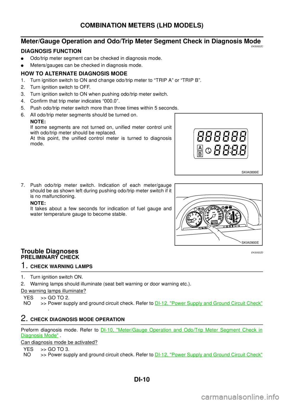
HOW TO ALTERNATE DIAGNOSIS MODE
1. Turn ignition switch to ON and change odo/trip meter to “TRIP A” or “TRIP B”.
2. Turn ignition switch to OFF.
3. Turn ignition switch to ON when pushing odo/trip meter switch.
4. Confirm that trip meter indicates “000.0”.
5. Push odo/trip meter switch more than three times within 5 seconds.
6. All odo/trip meter segments should be turned on.
NOTE:
If some segments are not turned on, unified meter control unit
with odo/trip meter should be replaced.
At this point, the unified control meter is turned to diagnosis
mode.
7. Push odo/trip meter switch. Indication of each meter/gauge
should be as shown left during pushing odo/trip meter switch if it
is no malfunctioning.
NOTE:
It takes about a few seconds for indication of fuel gauge and
water temperature gauge to become stable.
Trouble DiagnosesEKS002ZD
PRELIMINARY CHECK
1.CHECK WARNING LAMPS
1. Turn ignition switch ON.
2. Warning lamps should illuminate (seat belt warning or door warning etc.).
Do warning lamps illuminate?
YES >> GO TO 2.
NO >> Power supply and ground circuit check. Refer toDI-12, "
Power Supply and Ground Circuit Check"
.
2.CHECK DIAGNOSIS MODE OPERATION
Preform diagnosis mode. Refer toDI-10, "
Meter/Gauge Operation and Odo/Trip Meter Segment Check in
Diagnosis Mode".
Can diagnosis mode be activated?
YES >> GO TO 3.
NO >> Power supply and ground circuit check. Refer toDI-12, "
Power Supply and Ground Circuit Check"
SKIA0899E
SKIA0900E
Page 1065 of 3066

COMBINATION METERS (LHD MODELS)
DI-11
C
D
E
F
G
H
I
J
L
MA
B
DI
3.SEGMENTS CHECK
Check odo / trip meter segment.
Do all segments illuminate?
YES >> GO TO 4.
NO >> Replace combination meter.
4.CHECK FUEL WARNING LAMP
Check fuel warning lamp in diagnosis mode. Refer toDI-12, "
Power Supply and Ground Circuit Check".
Do fuel warning lamp illuminate?
OK >> GO TO 5.
NG >> Replace combination meter.
5.CHECK METER CIRCUIT
Check indication of each meter/gauge in self-diagnosis mode. Refer toDI-12, "
Power Supply and Ground Cir-
cuit Check".
OK or NG?
OK >> Symptom chart
NG >> Replace combination meter.
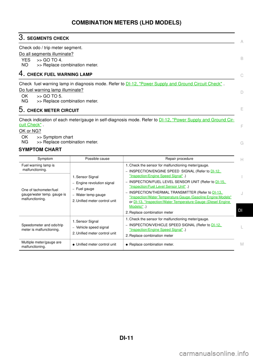
SYMPTOM CHART
Symptom Possible cause Repair procedure
Fuel warning lamp is
malfunctioning.
1. Sensor Signal
–Engine revolution signal
–Fuel gauge
–Water temp gauge
2. Unified meter control unit1. Check the sensor for malfunctioning meter/gauge.
–INSPECTION/ENGINE SPEED SIGNAL (Refer toDI-12,
"Inspection/Engine Speed Signal".)
–INSPECTION/FUEL LEVEL SENSOR UNIT (Refer toDI-15,
"Inspection/Fuel Level Sensor Unit".)
–INSPECTION/THERMAL TRANSMITTER (Refer toDI-13,
"Inspection/Water Temperature Gauge /Gasoline Engine Models"
orDI-13, "Inspection/Water Temperature Gauge (Diesel Engine
Models)".)
2. Replace combination meter One of tachometer/fuel
gauge/water temp. gauge is
malfunctioning.
Speedometer and odo/trip
meter is malfunctioning.1. Sensor Signal
–Vehicle speed signal
2. Unified meter control unit1. Check the sensor for malfunctioning meter/gauge.–INSPECTION/VEHICLE SPEED SIGNAL (Refer toDI-12,
"Inspection/Engine Speed Signal".)
2. Replace combination meter
Multiple meter/gauge are
malfunctioning.
lUnified meter control unitlReplace combination meter.
Page 1068 of 3066

DI-14
COMBINATION METERS (LHD MODELS)
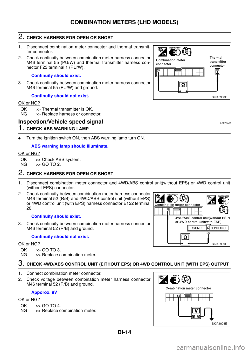
2.CHECK HARNESS FOR OPEN OR SHORT
1. Disconnect combination meter connector and thermal transmit-
ter connector.
2. Check continuity between combination meter harness connector
M46 terminal 55 (PU/W) and thermal transmitter harness con-
nector F23 terminal 1 (PU/W).
3. Check continuity between combination meter harness connector
M46 terminal 55 (PU/W) and ground.
OK or NG?
OK >> Thermal transmitter is OK.
NG >> Replace harness or connector.
Inspection/Vehicle speed signalEKS002ZH
1.CHECK ABS WARNING LAMP
lTurntheignitionswitchON,thenABSwarninglampturnON.
OK or NG?
OK >> Check ABS system.
NG >> GO TO 2.
2.CHECK HARNESS FOR OPEN OR SHORT
1. Disconnect combination meter connector and 4WD/ABS control unit(without EPS) or 4WD control unit
(without EPS) connector.
2. Check continuity between combination meter harness connector
M46 terminal 52 (R/B) and 4WD/ABS control unit (without EPS)
or 4WD control unit (with EPS) harness connector E122 terminal
20.
3. Check continuity between combination meter harness connector
M46 terminal 52 (R/B) and ground.
OK or NG?
OK >> GO TO 3.
NG >> Replace combination meter.
3.CHECK 4WD/ABS CONTROL UNIT (EITHOUT EPS) OR 4WD CONTROL UNIT (WITH EPS) OUTPUT
1. Connect combination meter connector.
2. Check voltage between combination meter harness connector
M46 terminal 52 (R/B) and ground.
OK or NG?
OK >> GO TO 4.
NG >> Replace combination meter.Continuity should exist.
Continuity should not exist.
SKIA0988E
ABS warning lamp should illuminate.
Continuity should exist.
Continuity should not exist.
SKIA0989E
Apporox. 9V
SKIA1004E