2003 NISSAN X-TRAIL reset
[x] Cancel search: resetPage 2345 of 3066

GW-42
FRONT DOOR GLASS AND REGULATOR
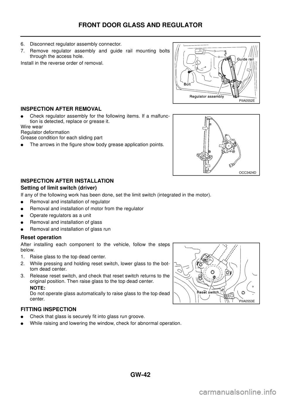
6. Disconnect regulator assembly connector.
7. Remove regulator assembly and guide rail mounting bolts
through the access hole.
Install in the reverse order of removal.
INSPECTION AFTER REMOVAL
lCheck regulator assembly for the following items. If a malfunc-
tion is detected, replace or grease it.
Wire wear
Regulator deformation
Grease condition for each sliding part
lThe arrows in the figure show body grease application points.
INSPECTION AFTER INSTALLATION
Setting of limit switch (driver)
If any of the following work has been done, set the limit switch (integrated in the motor).
lRemoval and installation of regulator
lRemoval and installation of motor from the regulator
lOperate regulators as a unit
lRemoval and installation of glass
lRemoval and installation of glass run
Reset operation
After installing each component to the vehicle, follow the steps
below.
1. Raise glass to the top dead center.
2. While pressing and holding reset switch, lower glass to the bot-
tom dead center.
3. Release reset switch, and check that reset switch returns to the
original position. Then raise glass to the top dead center.
NOTE:
Do not operate glass automatically to raise glass to the top dead
center.
FITTING INSPECTION
lCheck that glass is securely fit into glass run groove.
lWhile raising and lowering the window, check for abnormal operation.
PIIA0552E
OCC3424D
PIIA0553E
Page 2767 of 3066

STEERING WHEEL
PS-7
C
D
E
F
H
I
J
K
L
MA
B
PS
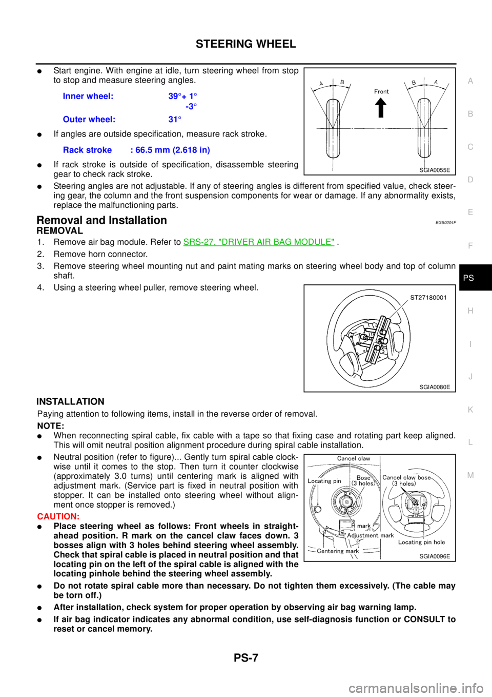
lStart engine. With engine at idle, turn steering wheel from stop
to stop and measure steering angles.
lIf angles are outside specification, measure rack stroke.
lIf rack stroke is outside of specification, disassemble steering
gear to check rack stroke.
lSteering angles are not adjustable. If any of steering angles is different from specified value, check steer-
ing gear, the column and the front suspension components for wear or damage. If any abnormality exists,
replace the malfunctioning parts.
Removal and InstallationEGS0004F
REMOVAL
1. Remove air bag module. Refer toSRS-27, "DRIVER AIR BAG MODULE".
2. Remove horn connector.
3. Remove steering wheel mounting nut and paint mating marks on steering wheel body and top of column
shaft.
4. Using a steering wheel puller, remove steering wheel.
INSTALLATION
Paying attention to following items, install in the reverse order of removal.
NOTE:
lWhen reconnecting spiral cable, fix cable with a tape so that fixing case and rotating part keep aligned.
This will omit neutral position alignment procedure during spiral cable installation.
lNeutral position (refer to figure)... Gently turn spiral cable clock-
wise until it comes to the stop. Then turn it counter clockwise
(approximately 3.0 turns) until centering mark is aligned with
adjustment mark. (Service part is fixed in neutral position with
stopper. It can be installed onto steering wheel without align-
ment once stopper is removed.)
CAUTION:
lPlace steering wheel as follows: Front wheels in straight-
ahead position. R mark on the cancel claw faces down. 3
bosses align with 3 holes behind steering wheel assembly.
Check that spiral cable is placed in neutral position and that
locating pin on the left of the spiral cable is aligned with the
locating pinhole behind the steering wheel assembly.
lDo not rotate spiral cable more than necessary. Do not tighten them excessively. (The cable may
be torn off.)
lAfter installation, check system for proper operation by observing air bag warning lamp.
lIf air bag indicator indicates any abnormal condition, use self-diagnosis function or CONSULT to
reset or cancel memory.Inner wheel: 39°+1°
-3°
Outer wheel: 31°
Rack stroke : 66.5 mm (2.618 in)
SGIA0055E
SGIA0080E
SGIA0096E
Page 2858 of 3066

RSU-6
REAR SUSPENSION ASSEMBLY
On-Vehicle Inspection and Service
EES0007F
Check axle and suspension parts for excessive play, wear, and damage.
lMove rear wheels (RH/LH) to check abnormal free play.
lRetighten all nuts and bolts to the specified torque.
lCheck strut for oil leakage and damage.
Wheel AlignmentEES0007G
DESCRIPTION
lMeasure wheel alignment under unladen conditions. “Unladen conditions” means that fuel, coolant, and
lubricant are full. However, spare tire, jack, and hand tools should be unloaded.
PRELIMINARY INSPECTION
1. Check the tires for improper air pressure and wear.
2. Check road wheels for runout.
3. Check wheel bearing axial endplay.
4. Check strut operation.
5. Check each mounting point of axle and suspension for looseness and deformation.
6. Check each link and arm for cracks, deformation, and other damage.
7. Check the vehicle posture.
CAMBER
Camber is preset at factory and cannot be adjusted.
lIf the camber is not within specification, inspect and replace any damaged or worn rear suspension parts.
TOE-IN
Measure toe-in using the following procedure.
lAlways perform following procedure on a flat surface.
lMake sure that no person is in front of the vehicle before push-
ing it.
1. Bounce rear of vehicle up and down to stabilize the posture.
2. Push the vehicle straight ahead about 5 m (16 ft).
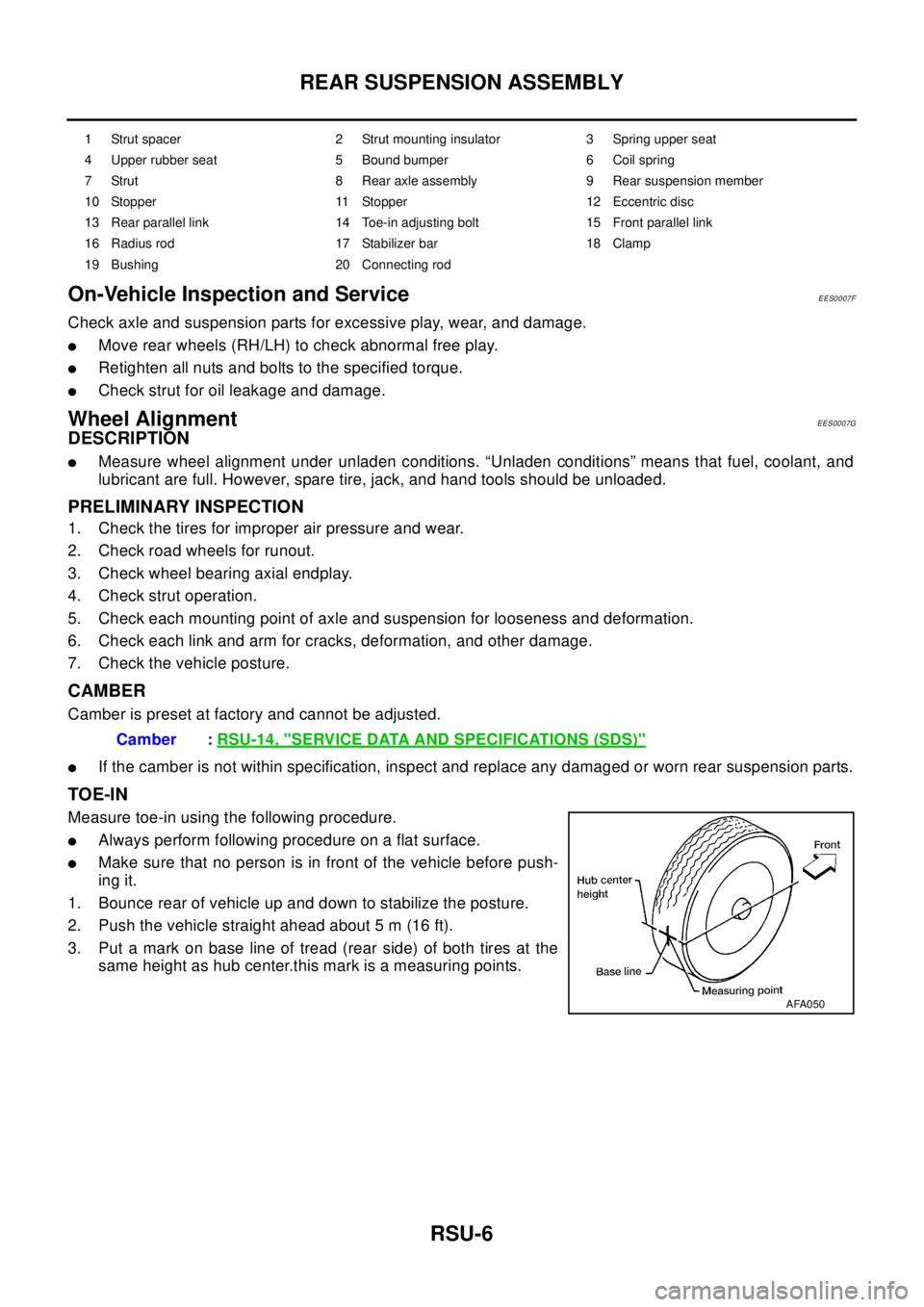
3. Put a mark on base line of tread (rear side) of both tires at the
same height as hub center.this mark is a measuring points.
1 Strut spacer 2 Strut mounting insulator 3 Spring upper seat
4 Upper rubber seat 5 Bound bumper 6 Coil spring
7 Strut 8 Rear axle assembly 9 Rear suspension member
10 Stopper 11 Stopper 12 Eccentric disc
13 Rear parallel link 14 Toe-in adjusting bolt 15 Front parallel link
16 Radius rod 17 Stabilizer bar 18 Clamp
19 Bushing 20 Connecting rod
Camber :RSU-14, "SERVICE DATA AND SPECIFICATIONS (SDS)"
AFA050
Page 2936 of 3066
![NISSAN X-TRAIL 2003 Electronic Repair Manual SRS-14
TROUBLE DIAGNOSIS
CONSULT-II FUNCTION
EHS000CP
DIAGNOSIS MODE FOR CONSULT-II
l“SELF-DIAG [CURRENT]”
A current Self-diagnosis result (also indicated by the number of warning lamp flashes in NISSAN X-TRAIL 2003 Electronic Repair Manual SRS-14
TROUBLE DIAGNOSIS
CONSULT-II FUNCTION
EHS000CP
DIAGNOSIS MODE FOR CONSULT-II
l“SELF-DIAG [CURRENT]”
A current Self-diagnosis result (also indicated by the number of warning lamp flashes in](/manual-img/5/57402/w960_57402-2935.png)
SRS-14
TROUBLE DIAGNOSIS
CONSULT-II FUNCTION
EHS000CP
DIAGNOSIS MODE FOR CONSULT-II
l“SELF-DIAG [CURRENT]”
A current Self-diagnosis result (also indicated by the number of warning lamp flashes in the Diagnosis
mode) is displayed on the CONSULT-II screen in real time. This refers to a malfunctioning part requiring
repairs.
l“SELF-DIAG [PAST]”
Diagnosis results previously stored in the memory are displayed on the CONSULT-II screen. The stored
results are not erased until memory erasing is executed.
l“TROUBLE DIAG RECORD”
With TROUBLE DIAG RECORD, diagnosis results previously erased by a reset operation can be dis-
played on the CONSULT-II screen.
l“ECU DISCRIMINATED NO.”
The diagnosis sensor unit for each vehicle model is assigned with its own, individual classification num-
ber. This number will be displayed on the CONSULT-II screen, as shown below. When replacing the diag-
nosis sensor unit, refer to the part number for the compatibility. After installation, replacement with a
correct unit can be checked by confirming this classification number on the CONSULT-II screen.
HOW TO CHANGE SELF-DIAGNOSIS MODE WITH CONSULT-II
From User Mode to Diagnosis Mode
After selecting “AIR BAG” on the “SELECT SYSTEM” screen, User mode automatically changes to Diagnosis
mode.
From Diagnosis Mode to User Mode
To return to User mode from Diagnosis mode, touch “BACK” key of CONSULT-II until “SELECT SYSTEM”
appears, Diagnosis mode automatically changes to User mode.
HOW TO ERASE SELF-DIAGNOSIS RESULTS
l“SELF-DIAG [CURRENT]”
A current Self-diagnosis result is displayed on the CONSULT-II screen in real time.
After the malfunction is repaired completely, no malfunction is detected on “SELF-DIAG [CURRENT]”.
l“SELF-DIAG [PAST]”
SRS803
SRS804
Page 3026 of 3066

TF-56
TROUBLE DIAGNOSIS
2.4WD CONTROL UNIT CONNECTOR CONNECTION INSPECTION
lCheck 4WD control unit connector for proper connection.
OK or NG
OK >> Reconnect the 4WD control unit connector properly and perform inspection again.
NG >> Repair or replace the connector.
HEAVY TIGHT-CORNER BRAKING SYMPTOM OCCURS WHEN THE VEHICLE IS DRIVEN IN
AUTO MODE AND THE STEERING WHEEL IS TURNED FULLY TO EITHER SIDE AFTER THE
ENGINE IS STARTED
1.PERFORM SELF-DIAGNOSIS.
Using CONSULT-II perform self-diagnosis.
OK or NG
OK >> GO TO 2. (No self-diagnosis malfunction indicated.)
NG >> Determine the location of the malfunction according to the result of self-diagnosis using CON-
SULT-II. (Malfunction is present in the 4WD system.)
2.CHECK USING THE DATA MONITOR FUNCTION OF THE CONSULT- II.
lPerform inspection by the data monitor function of the CONSULT-II.
lCheck that the operation is in AUTO mode.
lMeasure voltage when the accelerator pedal is not depressed. (Accelerator pedal not depressed: approx.
0.5V or lower)
lMeasure the current supplied to the 4WD solenoid valve. (Accelerator pedal not depressed: approx. 0A)
OK or NG
OK >> GO TO 3. (No self-diagnosis malfunction indicated.)
NG >>
lNot in AUTO mode. GO TO 3.
lVoltage when accelerator pedal is not depressed is higher than approximately 0.5V.
l4WD solenoid valve current when the accelerator pedal is not depressed is other than 0A.
lCountermeasure: Keep the vehicle idling for approximately 15 minutes before checking again.
(Voltage when accelerator pedal is not depressed will be automatically reset to zero during this
period.)