2003 NISSAN X-TRAIL sensor
[x] Cancel search: sensorPage 579 of 3066

ATC-1
AUTOMATIC AIR CONDITIONER
J AIR CONDITIONER
CONTENTS
C
D
E
F
G
H
I
K
L
M
SECTION
A
B
AT C
AUTOMATIC AIR CONDITIONER
PRECAUTIONS .......................................................... 4
Precautions for Supplemental Restraint System
(SRS) “AIR BAG” and “SEAT BELT PRE-TEN-
SIONER” .................................................................. 4
Precautions for Working with HFC-134a (R-134a)..... 4
General Refrigerant Precautions .............................. 4
Lubricant Precautions .............................................. 5
Precautions for Refrigerant Connection ................... 5
FEATURES OF NEW TYPE REFRIGERANT
CONNECTION ...................................................... 5
O-RING AND REFRIGERANT CONNECTION..... 6
Precautions for Servicing Compressor ..................... 7
Precautions for Service Equipment .......................... 8
RECOVERY/RECYCLING EQUIPMENT .............. 8
ELECTRONIC LEAK DETECTOR ........................ 8
VACUUM PUMP ................................................... 8
MANIFOLD GAUGE SET ...................................... 8
SERVICE HOSES ................................................. 9
SERVICE COUPLERS .......................................... 9
REFRIGERANT WEIGHT SCALE ........................ 9
CALIBRATING ACR4 WEIGHT SCALE ................ 9
CHARGING CYLINDER ...................................... 10
Precautions for Leak Detection Dye ....................... 10
IDENTIFICATION ................................................ 10
IDENTIFICATION LABEL FOR VEHICLE ........... 10
Wiring Diagrams and Trouble Diagnosis ................ 10
PREPARATION ..........................................................11
Special Service Tools ..............................................11
WITH GASOLINE ENGINE (CWV-615M COM-
PRESSOR) ..........................................................11
WITH DIESEL ENGINE (DKV-11G COMPRES-
SOR) ....................................................................11
HFC-134a (R-134a) Service Tools and Equipment... 12
REFRIGERATION SYSTEM ..................................... 16
Refrigerant Cycle ................................................... 16
REFRIGERANT FLOW ....................................... 16
FREEZE PROTECTION (WITH GASOLINE
ENGINE: CWV-615M COMPRESSOR) .............. 16
Refrigerant System Protection ............................... 16
REFRIGERANT PRESSURE SENSOR (WITHGASOLINE ENGINE: CWV-615M COMPRES-
SOR) ................................................................... 16
DUAL-PRESSURE SWITCH (WITH DIESEL
ENGINE: DKV-11G COMPRESSOR) .................. 16
PRESSURE RELIEF VALVE (WITH GASOLINE
ENGINE: CWV-615M COMPRESSOR) .............. 16
V-6 Variable Displacement Compressor (With Gas-
oline Engine: CWV-165M Compressor) .................. 17
GENERAL INFORMATION ................................. 17
DESCRIPTION .................................................... 17
Component Layout ................................................. 20
LUBRICANT .............................................................. 21
Maintenance of Lubricant Quantity in Compressor... 21
LUBRICANT ........................................................ 21
LUBRICANT RETURN OPERATION .................. 21
LUBRICANT ADJUSTING PROCEDURE FOR
COMPONENTS REPLACEMENT EXCEPT
COMPRESSOR .................................................. 22
LUBRICANT ADJUSTING PROCEDURE FOR
COMPRESSOR REPLACEMENT ....................... 22
AIR CONDITIONER CONTROL ............................... 24
Overview Air Conditioner LAN Control System ...... 24
System Construction .............................................. 24
OPERATION ........................................................ 24
TRANSMISSION DATA AND TRANSMISSION
ORDER ............................................................... 25
AIR MIX DOOR CONTROL (AUTOMATIC TEM-
PERATURE CONTROL) ..................................... 25
FAN SPEED CONTROL ...................................... 26
INTAKE DOOR CONTROL ................................. 26
OUTLET DOOR CONTROL ................................ 26
MAGNET CLUTCH CONTROL ........................... 26
SELF-DIAGNOSTIC SYSTEM ............................ 26
Overview of Control system .................................... 26
Control Operation ................................................... 27
DISPLAY SCREEN .............................................. 27
AUTO SWITCH ................................................... 27
TEMPERATURE DIAL (POTENTIO TEMPERA-
TURE CONTROL) ............................................... 27
A/C SWITCH ....................................................... 27
Page 580 of 3066

ATC-2
DEFROSTER (DEF) SWITCH ............................. 27
MODE SWITCH ................................................... 27
FAN SWITCH ...................................................... 27
OFF SWITCH ...................................................... 27
FRESH (FRE) SWITCH ....................................... 27
RECIRCULATION (REC) SWITCH ..................... 27
Discharge Air Flow ................................................. 28
System Description ................................................. 29
SWITCHES AND THEIR CONTROL FUNCTION... 29
TROUBLE DIAGNOSIS ............................................ 30
How to Perform Trouble Diagnoses for Quick and
Accurate Repair ...................................................... 30
WORK FLOW ...................................................... 30
SYMPTOM TABLE .............................................. 30
Component Parts and Harness Connector Location... 31
ENGINE COMPARTMENT .................................. 31
PASSENGER COMPARTMENT .......................... 32
Circuit Diagram ....................................................... 33
WITH GASOLINE ENGINE ................................. 33
WITH DIESEL ENGINE ....................................... 34
Wiring Diagram ....................................................... 35
WITH DASOLINE ENGINE ................................. 35
WITH DIESEL ENGINE ....................................... 38
Auto Amp. Terminals and Reference Value ............ 41
PIN CONNECTOR TERMINAL LAYOUT ............ 41
AUTO AMP. INSPECTION TABLE ...................... 41
Self-diagnosis Function .......................................... 42
DESCRIPTION .................................................... 42
PROCEDURE ...................................................... 43
AUXILIARY MECHANISM: TEMPERATURE
SETTING TRIMMER ........................................... 49
AUXILIARY MECHANISM: FOOT POSITION
SETTING TRIMMER ........................................... 50
AUXILIARY MECHANISM: INLET PORT MEM-
ORY FUNCTION (FOR LHD MODELS) .............. 51
Operational Check .................................................. 51
CHECKING MEMORY FUNCTION ..................... 51
CHECKING BLOEWER ....................................... 52
CHECKING DISCHARGE AIR ............................ 52
CHECKING RECIRCULATION ............................ 52
CHECKING TEMPERATURE DECREASE ......... 53
CHECKING TEMPERATURE INCREASE .......... 53
CHECKING AUTO MODE ................................... 53
Power Supply and Ground Circuit for Auto Amp. ... 53
INSPECTION FLOW ........................................... 54
COMPONENT DESCRIPTION ............................ 54
DIAGNOSTIC PROCEDURE .............................. 55
LAN System Circuit ................................................ 56
DIAGNOSTIC PROCEDURE .............................. 56
Mode Door Motor Circuit ........................................ 58
INSPECTION FLOW ........................................... 59
SYSTEM DESCRIPTION .................................... 60
COMPONENT DESCRIPTION ............................ 61
DIAGNOSTIC PROCEDURE .............................. 61
Air Mix Door Motor Circuit ...................................... 61
INSPECTION FLOW ........................................... 62
SYSTEM DESCRIPTION .................................... 62
COMPONENT DESCRIPTION ............................ 64DIAGNOSTIC PROCEDURE ...............................64
Intake Door Motor Circuit ........................................64
INSPECTION FLOW ............................................65
SYSTEM DESCRIPTION .....................................65
COMPONENT DESCRIPTION ............................66
DIAGNOSTIC PROCEDURE ...............................67
Blower Motor Circuit ................................................67
INSPECTION FLOW ............................................68
SYSTEM DESCRIPTION .....................................69
COMPONENT DESCRIPTION ............................70
DIAGNOSTIC PROCEDURE ...............................70
COMPONENT INSPECTION ...............................73
Magnet Clutch Circuit ..............................................73
INSPECTION FLOW ............................................74
SYSTEM DESCRIPTION .....................................74
DIAGNOSTIC PROCEDURE ...............................75
COMPONENT INSPECTION ...............................80
Insufficient Cooling ..................................................81
INSPECTION FLOW ............................................82
PERFORMANCE TEST DIAGNOSES ................83
PERFORMANCE CHART ....................................84
TROUBLE DIAGNOSES FOR ABNORMAL
PRESSURE .........................................................86
Insufficient Heating .................................................89
INSPECTION FLOW ............................................90
Noise .......................................................................91
INSPECTION FLOW ............................................91
Self-diagnosis .........................................................92
INSPECTION FLOW ............................................92
Memory Function ....................................................92
INSPECTION FLOW ............................................93
Ambient Sensor Circuit ...........................................93
COMPONENT DESCRIPTION ............................93
AMBIENT TEMPERATURE INPUT PROCESS...93
DIAGNOSTIC PROCEDURE ...............................94
COMPONENT INSPECTION ...............................95
In-vehicle Sensor Circuit .........................................95
COMPONENT DESCRIPTION ............................95
DIAGNOSTIC PROCEDURE ...............................96
COMPONENT INSPECTION ...............................97
Sunload Sensor Circuit ...........................................98
COMPONENT DESCRIPTION ............................98
SUNLOAD INPUT PROCESS .............................98
DIAGNOSTIC PROCEDURE ...............................98
COMPONENT INSPECTION ............................. 100
Intake Sensor Circuit ............................................. 101
COMPONENT DESCRIPTION .......................... 101
DIAGNOSTIC PROCEDURE ............................. 101
CONTROLLER ........................................................ 104
Removal and Installation ....................................... 104
Disassembly and Assembly .................................. 104
AMBIENT SENSOR ................................................ 105
Removal and Installation ....................................... 105
IN-VEHICLE SENSOR ............................................ 106
Removal and Installation ....................................... 106
SUNLOAD SENSOR ............................................... 107
Removal and Installation ....................................... 107
Page 581 of 3066

ATC-3
C
D
E
F
G
H
I
K
L
MA
B
AT C INTAKE SENSOR CIRCUIT ................................... 108
Removal and Installation ...................................... 108
BLOWER UNIT ....................................................... 109
Removal and Installation ...................................... 109
REMOVAL ......................................................... 109
INSTALLATION ................................................. 109
Disassembly and Assembly ................................. 109
BLOWER MOTOR ................................................... 111
Removal and Installation ...................................... . 111
INTAKE DOOR MOTOR .......................................... 112
Removal and Installation ....................................... 112
FAN CONTROL AMPLIFIER ................................... 113
Removal and Installation ....................................... 113
VENTILATION AIR FILTER ..................................... 114
Removal and Installation ....................................... 114
Function ................................................................ 114
Replacement Timing ............................................. 114
Replacement Procedures ...................................... 114
HEATER & COOLING UNIT ASSEMBLY ............... 115
Removal and Installation ....................................... 115
REMOVAL .......................................................... 115
INSTALLATION .................................................. 116
Disassembly and Assembly .................................. 116
MODE DOOR MOTOR ............................................ 118
Removal and Installation ....................................... 118
AIR MIX DOOR MOTOR .......................................... 119
Removal and Installation ....................................... 119
HEATER CORE ...................................................... 120
Removal and Installation ...................................... 120
DUCTS AND GRILLES .......................................... 121
Removal and Installation ...................................... 121
Ventilator Duct, Defroster Nozzle and Defroster
Ducts .................................................................... 121
Center Ventilator Grille ......................................... 121
Side Ventilator Grille ............................................. 121
Foot Duct .............................................................. 122
Floor duct ............................................................. 122
REFRIGERANT LINES ........................................... 123
HFC-134a (R-134a) Service Procedure ............... 123
SETTING OF SERVICE TOOLS AND EQUIP-
MENT ................................................................ 123
Components ......................................................... 125
Removal and Installation for Compressor ............ 126REMOVAL .........................................................126
INSTALLATION .................................................128
Removal and Installation for Compressor Clutch . 129
REMOVAL .........................................................129
INSTALLATION .................................................132
Removal and Installation for Low-pressure flexible
hose ......................................................................135
REMOVAL .........................................................135
INSTALLATION .................................................136
Removal and Installation for High-pressure flexible
hose ......................................................................136
REMOVAL .........................................................136
INSTALLATION .................................................136
Removal and Installation for High-pressure pipe ..137
REMOVAL .........................................................137
INSTALLATION .................................................137
Removal and Installation for Refrigerant Pressure
Sensor ..................................................................137
Removal and Installation for Dual-pressure Switch.138
Removal and Installation for Condenser ..............138
REMOVAL .........................................................138
INSTALLATION .................................................138
Removal and Installation for Evaporator ..............139
REMOVAL .........................................................139
INSTALLATION .................................................139
Removal and Installation for Expansion Valve ......140
Removal and Installation for Desiccant Assembly. 140
REMOVAL .........................................................140
INSTALLATION .................................................140
Checking for Refrigerant Leaks ............................140
Checking System for Leaks Using the Fluorescent
Leak Detector .......................................................141
Dye Injection .........................................................141
Electronic Refrigerant Leak Detector ....................141
PRECAUTIONS FOR HANDLING LEAK
DETECTOR .......................................................141
CHECKING PROCEDURE ...............................142
Service Data and Specifications (SDS) ................143
COMPRESSOR ................................................143
LUBRICANT ......................................................144
REFRIGERANT .................................................144
ENGINE IDLING SPEED ..................................144
BELT TENSION .................................................144
Page 583 of 3066

PRECAUTIONS
ATC-5
C
D
E
F
G
H
I
K
L
MA
B
AT C
property damage. Additional health and safety information may be obtained from refrigerant man-
ufacturers.
Lubricant PrecautionsEJS000T3
lUse only specified lubricant for the HFC-134a (R-134a) A/C system and HFC-134a (R-134a) components.
If lubricant other than that specified is used, compressor failure is likely to occur.
lThe specified HFC-134a (R-134a) lubricant rapidly absorbs moisture from the atmosphere. The following
handling precautions must be observed:
–When removing refrigerant components from a vehicle, immediately cap (seal) the component to minimize
the entry of moisture from the atmosphere.
–When installing refrigerant components to a vehicle, do not remove the caps (unseal) until just before con-
necting the components. Connect all refrigerant loop components as quickly as possible to minimize the
entry of moisture into system.
–Only use the specified lubricant from a sealed container. Immediately reseal containers of lubricant. With-
out proper sealing, lubricant will become moisture saturated and should not be used.
lAvoid breathing A/C refrigerant and lubricant vapor or mist. Exposure may irritate eyes, nose and throat.
Remove R-134a from the A/C system, using certified service equipment meeting requirements of SAE
J2210 (R-134a recycling equipment), or J2209 (R-134a recovery equipment). If accidental system dis-
charge occurs, ventilate work area before resuming service. Additional health and safety information may
be obtained from refrigerant and lubricant manufacturers.
lDo not allow lubricant (Nissan A/C System Oil Type S) to come in contact with styrofoam parts. Damage
may result.
Precautions for Refrigerant ConnectionEJS000T4
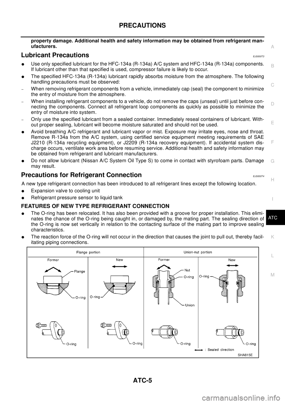
A new type refrigerant connection has been introduced to all refrigerant lines except the following location.
lExpansion valve to cooling unit
lRefrigerant pressure sensor to liquid tank
FEATURES OF NEW TYPE REFRIGERANT CONNECTION
lThe O-ring has been relocated. It has also been provided with a groove for proper installation. This elimi-
nates the chance of the O-ring being caught in, or damaged by, the mating part. The sealing direction of
the O-ring is now set vertically in relation to the contacting surface of the mating part to improve sealing
characteristics.
lThe reaction force of the O-ring will not occur in the direction that causes the joint to pull out, thereby facil-
itating piping connections.
SHA815E
Page 594 of 3066

ATC-16
REFRIGERATION SYSTEM
REFRIGERATION SYSTEM
PFP:KA990
Refrigerant CycleEJS000TD
REFRIGERANT FLOW
The refrigerant flows in the standard pattern, that is, through the compressor, the condenser with liquid tank,
through the evaporator, and back to the compressor. The refrigerant evaporation through the evaporator coil is
controlled by an externally equalized expansion valve, located inside the evaporator case.
FREEZE PROTECTION (WITH GASOLINE ENGINE: CWV-615M COMPRESSOR)
Under normal operating conditions, when the A/C is switched on, the compressor runs continuously, and the
evaporator pressure, and therefore, temperature is controlled by the V-6 variable displacement compressor to
prevent freeze up.
Refrigerant System ProtectionEJS000TE
REFRIGERANT PRESSURE SENSOR (WITH GASOLINE ENGINE: CWV-615M COMPRESSOR)
The refrigerant system is protected against excessively high or low pressures by the refrigerant pressure sen-
sor, located on the liquid tank. If the system pressure rises above, or falls below the specifications, the refriger-
ant pressure sensor detects the pressure inside the refrigerant line and sends the voltage signal to the ECM.
ECM makes the A/C relay go OFF and stops the compressor when pressure on the high pressure side
detected by refrigerant pressure sensor is over about 2,746 kPa (28 kg/cm
2, 398 psi), or below about 134 kPa
(1.4 kg/cm
2,20psi).
DUAL-PRESSURE SWITCH (WITH DIESEL ENGINE: DKV-11G COMPRESSOR)
The refrigerant system is protected against excessively high or low pressures by the dual-pressure switch,
located on the liquid tank. If the system pressure rises above or falls below the specifications, the dual-pres-
sure switch opens to interrupt the compressor operation.
PRESSURE RELIEF VALVE (WITH GASOLINE ENGINE: CWV-615M COMPRESSOR)
The refrigerant system is also protected by a pressure relief valve, located in the rear head of the compressor.
When the pressure of refrigerant in the system increases to an abnormal level [more than 3,727 kPa (38 kg/
Page 602 of 3066

ATC-24
AIR CONDITIONER CONTROL
AIR CONDITIONER CONTROL
PFP:27500
Overview Air Conditioner LAN Control SystemEJS000TI
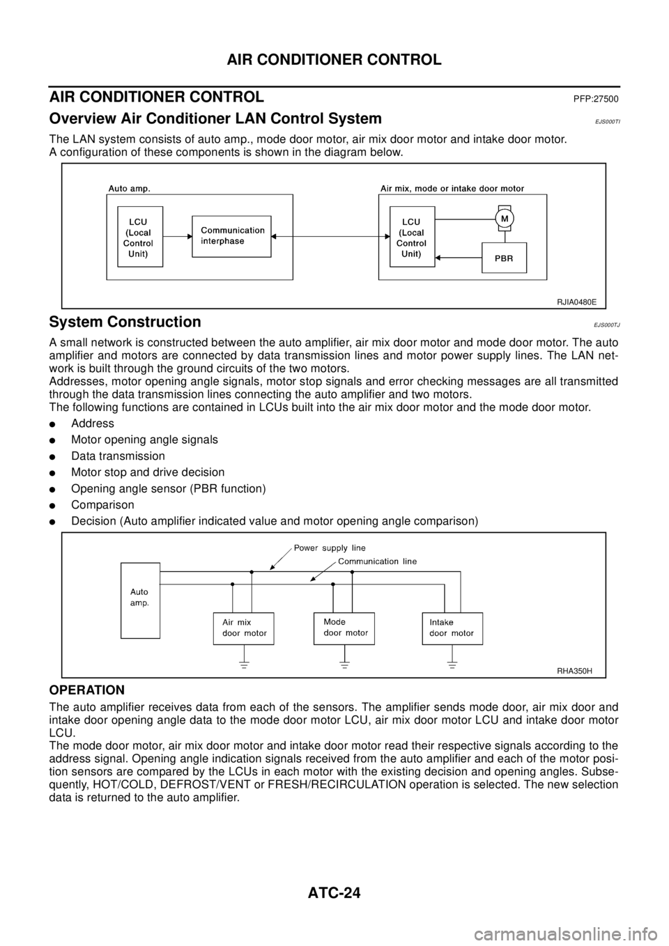
The LAN system consists of auto amp., mode door motor, air mix door motor and intake door motor.
A configuration of these components is shown in the diagram below.
System ConstructionEJS000TJ
A small network is constructed between the auto amplifier, air mix door motor and mode door motor. The auto
amplifier and motors are connected by data transmission lines and motor power supply lines. The LAN net-
work is built through the ground circuits of the two motors.
Addresses, motor opening angle signals, motor stop signals and error checking messages are all transmitted
through the data transmission lines connecting the auto amplifier and two motors.
The following functions are contained in LCUs built into the air mix door motor and the mode door motor.
lAddress
lMotor opening angle signals
lData transmission
lMotor stop and drive decision
lOpening angle sensor (PBR function)
lComparison
lDecision (Auto amplifier indicated value and motor opening angle comparison)
OPERATION
The auto amplifier receives data from each of the sensors. The amplifier sends mode door, air mix door and
intake door opening angle data to the mode door motor LCU, air mix door motor LCU and intake door motor
LCU.
The mode door motor, air mix door motor and intake door motor read their respective signals according to the
address signal. Opening angle indication signals received from the auto amplifier and each of the motor posi-
tion sensors are compared by the LCUs in each motor with the existing decision and opening angles. Subse-
quently, HOT/COLD, DEFROST/VENT or FRESH/RECIRCULATION operation is selected. The new selection
data is returned to the auto amplifier.
RJIA0480E
RHA350H
Page 604 of 3066

ATC-26
AIR CONDITIONER CONTROL
FAN SPEED CONTROL
Blower speed is automatically controlled based on temperature setting, ambient temperature, in-vehicle tem-
perature, intake temperature, amount of sunload and air mix door position.
With FAN switch set to AUTO, the blower motor starts to gradually increase air flow volume.
When engine coolant temperature is low, the blower motor operation is delayed to prevent cool air from flow-
ing.
INTAKE DOOR CONTROL
The intake doors are automatically controlled by: The temperature setting, ambient temperature, in-vehicle
temperature, intake temperature, amount of sunload and ON-OFF operation of the compressor.
OUTLET DOOR CONTROL
The outlet door is automatically controlled by: The temperature setting, ambient temperature, in-vehicle tem-
perature, intake temperature and amount of sunload.
MAGNET CLUTCH CONTROL
The ECM controls compressor operation using input signals from the throttle position sensor and auto ampli-
fier.
SELF-DIAGNOSTIC SYSTEM
The self-diagnostic system is built into the auto amplifier (LCU) to quickly locate the cause of problems.
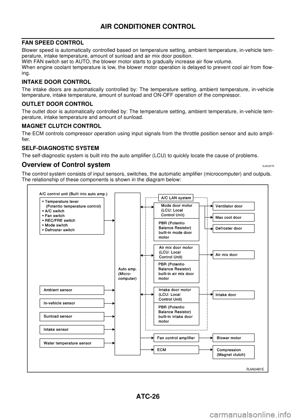
Overview of Control systemEJS000TK
The control system consists of input sensors, switches, the automatic amplifier (microcomputer) and outputs.
The relationship of these components is shown in the diagram below:
RJIA0481E
Page 619 of 3066

TROUBLE DIAGNOSIS
ATC-41
C
D
E
F
G
H
I
K
L
MA
B
AT C
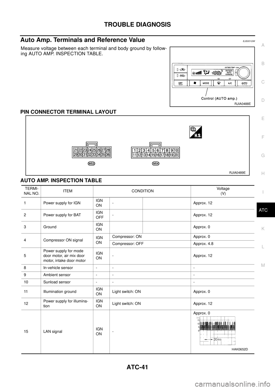
Auto Amp. Terminals and Reference ValueEJS001GW
Measure voltage between each terminal and body ground by follow-
ing AUTO AMP. INSPECTION TABLE.
PIN CONNECTOR TERMINAL LAYOUT
AUTO AMP. INSPECTION TABLE
RJIA0488E
RJIA0489E
TERMI-
NAL NO.ITEM CONDITIONVo l ta g e
(V)
1 Power supply for IGNIGN
ON- Approx. 12
2 Power supply for BATIGN
OFF- Approx. 12
3 GroundIGN
ONApprox. 0
4 Compressor ON signalIGN
ONCompressor: ON Approx. 0
Compressor: OFF Approx. 4.8
5Power supply for mode
door motor, air mix door
motor, intake door motorIGN
ON- Approx. 12
8 In-vehicle sensor - - -
9 Ambient sensor - - -
10 Sunload sensor - - -
11 Illumination groundIGN
ONLight switch: ON Approx. 0
12Power supply for illumina-
tionIGN
ONLight switch: ON Approx. 12
15 LAN signalIGN
ON-Approx. 0
HAK0652D