Page 3247 of 3502
CHARGING SYSTEM
SC-29
C
D
E
F
G
H
I
J
L
MA
B
SC
Trouble DiagnosisBKS001ML
Before performing an alternator test, make sure that the battery is fully charged. A 30-volt voltmeter and suit-
able test probes are necessary for the test. The alternator can be checked easily by referring to the Inspection
Table.
�Before starting, inspect the fusible link.
�Use fully charged battery.
WITH IC REGULATOR
NOTE:
�If the inspection result is OK even though the charging system is malfunctioning, check the “B” terminal
connection (Check the tightening torque) and voltage drop.
�Check condition of rotor coil, rotor slip ring, brush and stator coil. If necessary, replace malfunctioning
parts with new ones.
SKIB0466E
Page 3248 of 3502
SC-30
CHARGING SYSTEM
Removal and InstallationBKS0027E
VQ23DE AND VQ35DE MODELS
Removal
1. Disconnect negative battery cable.
2. Remove engine undercover, using power tools.
3. Remove radiator. Refer to CO-37, "
RADIATOR" in “ENGINE COOLING SYSTEM (CO)” section.
4. Remove alternator and air conditioner compressor belt. Refer to EM-129, "
Removal and Installation" in
“ENGINE MECHANICAL (EM)” section.
5. Remove idler pulley.
6. Remove alternator mounting nut, using power tools.
7. Remove through bolt.
8. Disconnect alternator connector.
9. Remove B terminal nut.
10. Remove ground harness clip and ground harness mounting nut.
1. Through-bolt 2. Cylinder block 3. Timing chain case
4. Alternator mounting nut 5. Alternator 6. Alternator connector
7. B terminal harness 8. B terminal nut 9. Alternator mounting bolt
10. Alternator bracket 11. Alternator bracket mounting bolt
PKIA2926J
PKIA2431E
PKIA2432E
Page 3249 of 3502
CHARGING SYSTEM
SC-31
C
D
E
F
G
H
I
J
L
MA
B
SC
11. Remove alternator mounting bolt, using power tools.
12. Remove alternator bracket mounting bolt and alternator bracket.
13. Remove alternator to the direction of upper side the vehicle.
Installation
Note the following, and install in the reverse order of removal.
�Install alternator, and check tension of belt. Refer to EM-128, "Checking Drive Belts" in “ENGINE
MECHANICAL (EM)” section.
CAUTION:
Be sure to tighten B terminal nut carefully.
PKIA2433E
Page 3250 of 3502
SC-32
CHARGING SYSTEM
QR20DE MODELS
Removal
1. Disconnect negative battery cable.
2. Remove drive belt. Refer to EM-14, "
Removal and Installation" .
3. Remove IPDM E/R bracket mounting bolts.
4. Slide IPDM E/R to the direction of arrow.
5. Disconnect alternator connector.
6. Remove B terminal nut.
7. Remove ground harness clip and ground harness bolt.
8. Remove alternator mounting bolts, using power tools.
9. Remove alternator to the direction of upper side the vehicle.
Installation
Note the following, and install in the reverse order of removal.
�Install alternator, and check tension of belt. Refer to EM-14, "Checking Drive Belts" in “ENGINE
MECHANICAL (EM)” section.
CAUTION:
Be sure to tighten B terminal nut carefully.
1. Alternator bracket 2. Alternator mounting bolt (upper) 3. Alternator mounting bolt (lower)
4. Alternator 5. B terminal harness 6. B terminal nut
7. Alternator connector
PKIA2930J
PKIA4811E
PKIA4812E
Page 3251 of 3502
CHARGING SYSTEM
SC-33
C
D
E
F
G
H
I
J
L
MA
B
SC
Disassembly and AssemblyBKS0027D
VQ23DE AND VQ35DE MODELS
PKIB9030E
1. Stator 2. Rear bearing 3. Rotor assembly
4. Retainer 5. Front bearing 6. Front cover
7. Pulley 8. Pulley nut 9. Fun guide
10. Double labyrinth seal 11. IC voltage regulator assembly 12. Diode assembly
13. Rear cover 14. Terminal set 15. Through-bolt
Page 3252 of 3502
SC-34
CHARGING SYSTEM
QR20DE MODELS
DISASSEMBLY
Rear Cover
1. Remove through-bolt (4).
2. Remove rear cover.
NOTE:
Rear cover may be hard to remove because a ring is used to
lock outer race of rear bearing. To facilitate removal of rear
cover, heat just bearing box section with a 200 W soldering iron
until the temperature increases by about 30 °C.
CAUTION:
Never use a heat gun, as it can damage diode assembly.
PKIC8724E
1. Stator 2. Rear bearing 3. Rotor assembly
4. Retainer 5. Front bearing 6. Front cover
7. Pulley 8. Fun guide 9. Double labyrinth seal
10. IC voltage regulator assembly 11. Diode assembly 12. Rear cover
13. Terminal set 14. Through-bolt
SEL032Z
Page 3253 of 3502
CHARGING SYSTEM
SC-35
C
D
E
F
G
H
I
J
L
MA
B
SC
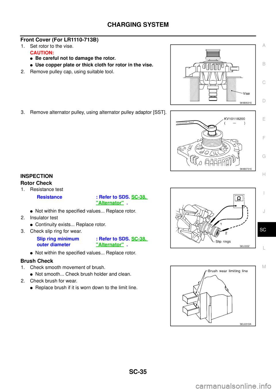
Front Cover (For LR1110-713B)
1. Set rotor to the vise.
CAUTION:
�Be careful not to damage the rotor.
�Use copper plate or thick cloth for rotor in the vise.
2. Remove pulley cap, using suitable tool.
3. Remove alternator pulley, using alternator pulley adaptor [SST].
INSPECTION
Rotor Check
1. Resistance test
�Not within the specified values... Replace rotor.
2. Insulator test
�Continuity exists... Replace rotor.
3. Check slip ring for wear.
�Not within the specified values... Replace rotor.
Brush Check
1. Check smooth movement of brush.
�Not smooth... Check brush holder and clean.
2. Check brush for wear.
�Replace brush if it is worn down to the limit line.
SKIB0531E
SKIB0731E
Resistance : Refer to SDS. SC-38,
"Alternator" .
Slip ring minimum
outer diameter: Refer to SDS. SC-38,
"Alternator" .SEL033Z
SEL631DA
Page 3254 of 3502
SC-36
CHARGING SYSTEM
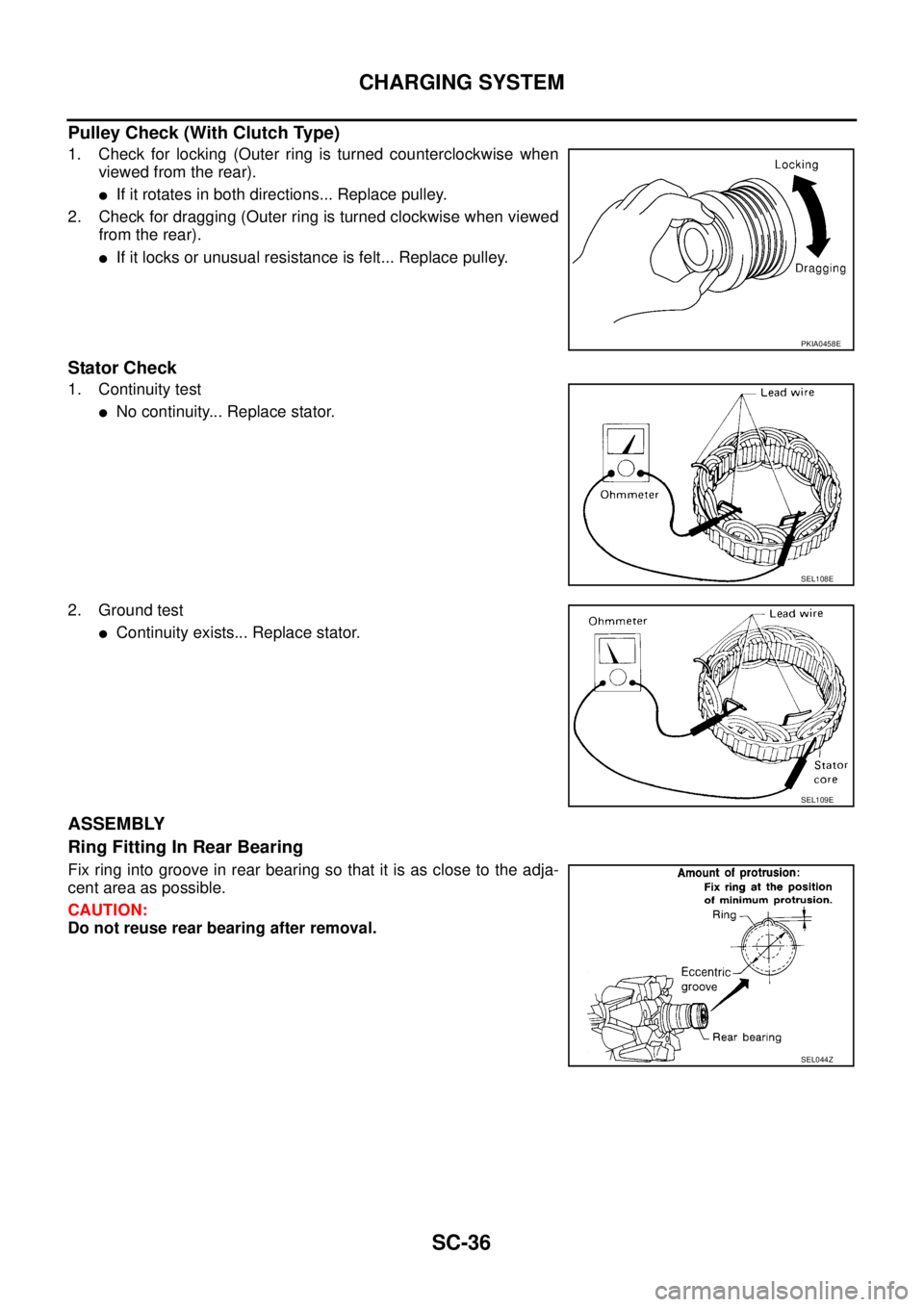
Pulley Check (With Clutch Type)
1. Check for locking (Outer ring is turned counterclockwise when
viewed from the rear).
�If it rotates in both directions... Replace pulley.
2. Check for dragging (Outer ring is turned clockwise when viewed
from the rear).
�If it locks or unusual resistance is felt... Replace pulley.
Stator Check
1. Continuity test
�No continuity... Replace stator.
2. Ground test
�Continuity exists... Replace stator.
ASSEMBLY
Ring Fitting In Rear Bearing
Fix ring into groove in rear bearing so that it is as close to the adja-
cent area as possible.
CAUTION:
Do not reuse rear bearing after removal.
PKIA0458E
SEL108E
SEL109E
SEL044Z


.
2. Remove rear cover.
NOTE:
Rear cover may be hard to remove because a ring is used to
lock outer race of rear")