Page 3225 of 3502
BATTERY
SC-7
C
D
E
F
G
H
I
J
L
MA
B
SC
Battery Test and Charging ChartBKS001MC
CHART I
*1:SC-5, "SPECIFIC GRAVITY
CHECK"
*2:SC-8, "CHART II"*3:SC-9, "A: SLOW CHARGE"
*4:SC-10, "B: STANDARD CHARGE"*5:SC-12, "C: QUICK CHARGE"
PKIA3696E
Page 3226 of 3502
SC-8
BATTERY
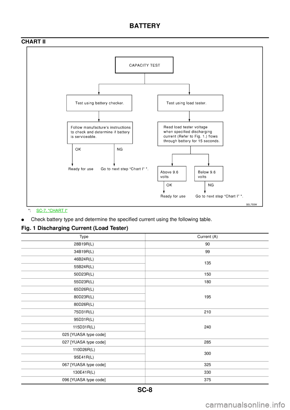
CHART II
�Check battery type and determine the specified current using the following table.
Fig. 1 Discharging Current (Load Tester)
*:SC-7, "CHART I"
SEL755W
Type Current (A)
28B19R(L) 90
34B19R(L) 99
46B24R(L)
135
55B24R(L)
50D23R(L) 150
55D23R(L) 180
65D26R(L)
195 80D23R(L)
80D26R(L)
75D31R(L) 210
95D31R(L)
240 115D31R(L)
025 [YUASA type code]
027 [YUASA type code] 285
110D26R(L)
300
95E41R(L)
067 [YUASA type code] 325
130E41R(L) 330
096 [YUASA type code] 375
Page 3227 of 3502
BATTERY
SC-9
C
D
E
F
G
H
I
J
L
MA
B
SC
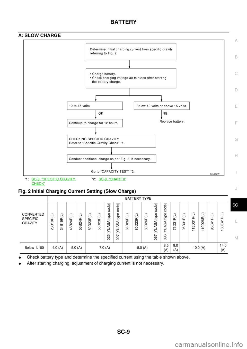
A: SLOW CHARGE
Fig. 2 Initial Charging Current Setting (Slow Charge)
�Check battery type and determine the specified current using the table shown above.
�After starting charging, adjustment of charging current is not necessary.
*1:SC-5, "SPECIFIC GRAVITY
CHECK"
*2:SC-8, "CHART II"
SEL756W
CONVERTED
SPECIFIC
GRAVITYBATTERY TYPE
28B19R(L)
34B19R(L)
46B24R(L)
55B24R(L)
50D23R(L)
55D23R(L)
025 [YUASA type code]
027 [YUASA type code]
65D26R(L)
80D23R(L)
80D26R(L)
067 [YUASA type code]
096 [YUASA type code]
75D31R(L)
95D31R(L)
115D31R(L)
110D26R(L)
95E41R(L)
130E41R(L)
Below 1.100 4.0 (A) 5.0 (A) 7.0 (A) 8.0 (A)8.5
(A)9.0
(A)10.0 (A)14.0
(A)
Page 3228 of 3502

CAUTION:
�Set charging current to specified value in Fig. 2. If charger is not capable of producing specified
current value, set its charging cur")
SC-10
BATTERY
Fig. 3 Additional Charge (Slow Charge)
CAUTION:
�Set charging current to specified value in Fig. 2. If charger is not capable of producing specified
current value, set its charging current as close to that value as possible.
�Keep battery away from open flame while it is being charged.
�When connecting charger, connect leads first, then turn on charger. Never turn on charger first, as
this may cause a spark.
�If battery temperature rises above 55°C (131°F), stop charging. Always charge battery when its
temperature is below 55°C (131°F).
B: STANDARD CHARGE
Fig. 4 Initial Charging Current Setting (Standard Charge)
*:SC-8, "CHART II"
SEL757W
*1:SC-5, "SPECIFIC GRAVITY
CHECK"
*2:SC-8, "CHART II"
SEL758W
CONVERTED
SPECIFIC
GRAVITYBATTERY TYPE
28B19R(L)
34B19R(L)
46B24R(L)
55B24R(L)
50D23R(L)
55D23R(L)
025 YUASA type code
027 YUASA type code
65D26R(L)
80D23R(L)
80D26R(L)
067 YUASA type code
096 YUASA type code
75D31R(L)
95D31R(L)
115D31R(L)
110D26R(L)
95E41R(L)
130E41R(L)
1.100 - 1.130 4.0 (A) 5.0 (A) 6.0 (A) 7.0 (A)8.0
(A)9.0 (A)13.0
(A)
1.130 - 1.160 3.0 (A) 4.0 (A) 5.0 (A) 6.0 (A)7.0
(A)8.0 (A)11 . 0
(A)
Page 3229 of 3502

BATTERY
SC-11
C
D
E
F
G
H
I
J
L
MA
B
SC
�Check battery type and determine the specified current using the table shown above.
�After starting charging, adjustment of charging current is not necessary.
Fig. 5 Additional Charge (Standard Charge)
CAUTION:
�Never use standard charge method on a battery whose specific gravity is less than 1.100.
�Set charging current to specified value in Fig. 4. If charger is not capable of producing specified
current value, set its charging current as close to that value as possible.
�Keep battery away from open flame while it is being charged.
�When connecting charger, connect leads first, then turn on charger. Never turn on charger first, as
this may cause a spark.
�If battery temperature rises above 55°C (131°F), stop charging. Always charge battery when its
temperature is below 55°C (131°F).
1.160 - 1.190 2.0 (A) 3.0 (A) 4.0 (A) 5.0 (A)6.0
(A)7.0 (A)9.0
(A)
1.190 - 1.220 2.0 (A) 2.0 (A) 3.0 (A) 4.0 (A)5.0
(A)5.0 (A)7.0
(A) CONVERTED
SPECIFIC
GRAVITYBATTERY TYPE
28B19R(L)
34B19R(L)
46B24R(L)
55B24R(L)
50D23R(L)
55D23R(L)
025 YUASA type code
027 YUASA type code
65D26R(L)
80D23R(L)
80D26R(L)
067 YUASA type code
096 YUASA type code
75D31R(L)
95D31R(L)
115D31R(L)
110D26R(L)
95E41R(L)
130E41R(L)
*:SC-8, "CHART II"
SEL759W
Page 3230 of 3502

�Check battery type and determine the specified current using the table shown above.
�After sta")
SC-12
BATTERY
C: QUICK CHARGE
Fig. 6 Initial Charging Current Setting and Charging Time (Quick Charge)
�Check battery type and determine the specified current using the table shown above.
�After starting charging, adjustment of charging current is not necessary.
CAUTION:
�Never use quick charge method on a battery whose specific gravity is less than 1.100.
�Set initial charging current to specified value in Fig. 6. If charger is not capable of producing spec-
ified current value, set its charging current as close to that value as possible.
�Keep battery away from open flame while it is being charged.
�When connecting charger, connect leads first, then turn on charger. Never turn on charger first, as
this may cause a spark.
�Be careful of a rise in battery temperature because a large current flow is required during quick-
charge operation.
If battery temperature rises above 55°C (131°F), stop charging. Always charge battery when its
temperature is below 55°C (131°F).
�Never exceed the charging time specified in Fig. 6, because charging battery over the charging
time can cause deterioration of the battery.
*:SC-8, "CHART II"
SEL760W
BATTERY TYPE
28B19R(L)
34B19R(L)
46B24R(L)
55B24R(L)
50D23R(L)
55D23R(L)
65D26R(L)
80D23R(L)
80D26R(L)
025 [YUASA type code]
027 [YUASA type code]
067 [YUASA type code]
096 [YUASA type code]
75D31R(L)
95D31R(L)
115D31R(L)
110D26R(L)
95E41R(L)
130E41R(L)
CURRENT [A] 10 (A) 15 (A) 20 (A) 25 (A) 30 (A)40
(A)
CONVERTED SPECIFIC GRAVITY
1.100 -
1.1302.5 hours
1.130 -
1.1602.0 hours
1.160 -
1.1901.5 hours
1.190 -
1.2201.0 hours
Above
1.2200.75 hours (45 min.)
Page 3245 of 3502

CHARGING SYSTEM
SC-27
C
D
E
F
G
H
I
J
L
MA
B
SC
CHARGING SYSTEMPFP:23100
System DescriptionBKS001MJ
The alternator provides DC voltage to operate the vehicle's electrical system and to keep the battery charged.
The voltage output is controlled by the IC regulator.
Power is supplied at all times:
�through 10A fuse (No. 36, located in the fuse and fusible link block)
�to alternator terminal 4 (“S” terminal).
“B” terminal supplies power to charge the battery and operate the vehicle's electrical system. Output voltage is
controlled by the IC regulator at terminal 4 (“S” terminal) detecting the input voltage.
The charging circuit is protected by the 120A fusible link (letter A, located in the fusible link holder).
The alternator is grounded to the engine block.
With the ignition switch in the ON or START position, power is supplied:
�through 10A fuse [No. 14, located in the fuse block (J/B)]
�to combination meter terminal 8 for the charge warning lamp.
Ground is supplied:
�to combination meter terminal 22
�through alternator terminal 3 (“L” terminal)
�to alternator terminal “E”
�through ground E2.
The charge warning lamp will illuminate. When the alternator is providing sufficient voltage with the engine
running, the ground is opened and the charge warning lamp will go off.
If the charge warning lamp illuminates with the engine running, a malfunction is indicated.
MALFUNCTION INDICATOR
The IC regulator warning function activates to illuminate charge warning lamp, if any of the following symp-
toms occur while alternator is operating:
�Excessive voltage is produced.
�No voltage is produced.
Page 3246 of 3502
SC-28
CHARGING SYSTEM
Wiring Diagram — CHARGE —BKS001MK
TKWM4763E