Page 3142 of 3502
PS-28
POWER STEERING GEAR AND LINKAGE
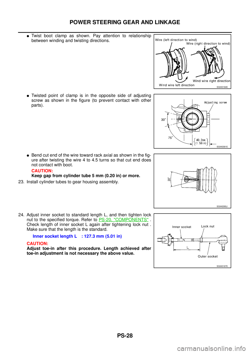
�Twist boot clamp as shown. Pay attention to relationship
between winding and twisting directions.
�Twisted point of clamp is in the opposite side of adjusting
screw as shown in the figure (to prevent contact with other
parts).
�Bend cut end of the wire toward rack axial as shown in the fig-
ure after twisting the wire 4 to 4.5 turns so that cut end does
not contact with boot.
CAUTION:
Keep gap from cylinder tube 5 mm (0.20 in) or more.
23. Install cylinder tubes to gear housing assembly.
24. Adjust inner socket to standard length L, and then tighten lock
nut to the specified torque. Refer to PS-20, "
COMPONENTS" .
Check length of inner socket L again after tightening lock nut .
Make sure that the length is the standard.
CAUTION:
Adjust toe-in after this procedure. Length achieved after
toe-in adjustment is not necessary the above value.
SGIA0164E
SGIA0361E
SGIA0260J
Inner socket length L : 127.3 mm (5.01 in)
SGIA0167E
Page 3147 of 3502

POWER STEERING OIL PUMP
PS-33
C
D
E
F
H
I
J
K
L
MA
B
PS
ASSEMBLY
NOTE:
Secure oil pump in a vise if necessary.
CAUTION:
Use copper plates when securing in a vise.
1. Apply recommended grease to oil seal lips (1). Apply recom-
mended fluid to around oil seal, and then install oil seal to body
assembly.
2. Apply recommended fluid to drive shaft, and press drive shaft
into body assembly, then install snap ring.
3. Apply recommended fluid to O-ring, and then install O-ring into
body assembly.
4. Install side plate to body assembly.
5. Install dowel pin (3) into dowel pin hole (A), and then install cam
ring (2) pointing it's D
1 side toward the body assembly (1) side
as shown in the figure.
�When installing cam ring, turn carved face with a letter E (B)
of it to rear cover.
CAUTION:
Do not confuse the assembling direction of cam ring. If
cam ring is installed facing the incorrect direction, it may
cause oil pump operation malfunction.
6. Install rotor to body assembly.
SGIA1150E
SGIA0422E
SGIA1166E
Page 3176 of 3502

RF-12
SUNROOF
The operation condition is the following.
�automatic close operation and tilt down when ignition switch is in the ON position
�automatic close operation and tilt down during retained power operation.
MEMORY RESET PROCEDURE
1. Please observe the following instructions while confirming the sunroof operation.
NOTE:
Do not disconnect the electronic power while the sunroof is operating or within 5 seconds after the sunroof
stops.
2. Initialization of system should be conducted after the following conditions.
�When the battery is out or connector is disconnected while sunroof is operating or within 5 seconds
after sunroof stops.
�When the sunroof motor is changed.
�When the sunroof does not operate normally. (Incomplete initialization conditions)
INITIALIZATION PROCEDURE
If the sunroof does not close or open automatically, use the following procedure to return sunroof operation to
normal.
1. Press and hold the switch to the CLOSE/UP side for approximately 10 seconds.
2. The glass lid will move toward tilt up direction and will be stopped mechanically, and then it will be auto-
matically fully closed. Then glass lid will be automatically operated in sequence of “tilt up” → “tilt down” →
“slide open” → “slide close”. (Keep pressing the switch during this operation)
3. After the glass lid stops, release the switch after 5 seconds.
4. If sunroof switch operates normally, this initialization is done.
Page 3377 of 3502
 “AIR BAG” and “SEAT
BELT PRE-TENSIONER”
BHS0003U
The Supplemental Restr")
PRECAUTIONS
SRS-3
C
D
E
F
G
I
J
K
L
MA
B
SRS
PRECAUTIONSPFP:00001
Precautions for Supplemental Restraint System (SRS) “AIR BAG” and “SEAT
BELT PRE-TENSIONER”
BHS0003U
The Supplemental Restraint System such as “AIR BAG” and “SEAT BELT PRE-TENSIONER”, used along
with a front seat belt, helps to reduce the risk or severity of injury to the driver and front passenger for certain
types of collision. Information necessary to service the system safely is included in the SRS and SB section of
this Service Manual.
WARNING:
�To avoid rendering the SRS inoperative, which could increase the risk of personal injury or death
in the event of a collision which would result in air bag inflation, all maintenance must be per-
formed by an authorized NISSAN/INFINITI dealer.
�Improper maintenance, including incorrect removal and installation of the SRS, can lead to per-
sonal injury caused by unintentional activation of the system. For removal of Spiral Cable and Air
Bag Module, see the SRS section.
�Do not use electrical test equipment on any circuit related to the SRS unless instructed to in this
Service Manual. SRS wiring harnesses can be identified by yellow and/or orange harnesses or
harness connectors.
Precautions for SRS “AIR BAG” and “SEAT BELT PRE-TENSIONER” ServiceBHS0003V
�Do not use electrical test equipment to check SRS circuits unless instructed to in this Service Manual.
�Before servicing the SRS, turn ignition switch OFF, and disconnect both battery cables. Then wait at least
3 minutes.
For approximately 3 minutes after the cables are removed, it is still possible for the air bag and seat belt
pre-tensioner to deploy. Therefore, do not work on any SRS connectors or wires until at least 3 minutes
have passed.
�Diagnosis sensor unit must always be installed with their arrow marks “⇐” pointing towards the front of the
vehicle for proper operation. Also check diagnosis sensor unit for cracks, deformations or rust before
installation and replace if required.
�The spiral cable must be set to the neutral position since its rotations are limited. Do not attempt to turn
steering wheel or column, if steering gear was disconnected from the column shaft.
�Handle air bag module carefully. Always put a driver air bag module with the pad side facing upward.
�Conduct self-diagnosis to check entire SRS for proper function after replacing any components.
�After an air bag is deployed, the front instrument panel assembly should be replaced if damaged.
�Always replace instrument panel pad following front passenger air bag deployment.
Page 3475 of 3502

FRONT WIPER AND WASHER SYSTEM
WW-37
C
D
E
F
G
H
I
J
L
MA
B
WW
Removal and Installation of Front Washer NozzleBKS003WB
REMOVAL
1. Open hood.
2. While pushing nozzle spray point side along body, use the noz-
zle stop point as the support point and rotate nozzle to remove it
from body.
3. Remove washer tube.
INSTALLATION
1. Install washer tube in nozzle.
2. Install nozzle to the vehicle.
3. Adjust nozzle spray location. Refer to WW-36, "
Washer Nozzle Adjustment" .
CAUTION:
The spray points differ, so be sure to install left and right nozzles correctly.
Inspection for Washer NozzleBKS003WC
CHECK VALVE INSPECTION
Blow check valve. Confirm that the air ventilates. Also confirm that
inhalation is impossible.
Inspection of Front Wiper and Washer Switch CircuitBKS003WD
Refer to LT- 1 8 5 , "Combination Switch Inspection" .
Removal and Installation of Front Wiper and Washer SwitchBKS003WE
REMOVAL
1. Remove steering column cover. Refer to IP-11, "Removal and Installation" .
2. Disconnect the wiper and washer switch connector.
3. Pull wiper and washer switch toward the passenger door while
pressing pawls in direction shown by the arrow in the figure, and
remove it from the base.
INSTALLATION
Installation is the reverse order of removal.
SKIA0291J
PKIA1403E
SKIB0909E