Page 720 of 3502
BL-62
REMOTE KEYLESS ENTRY SYSTEM
2. CHECK TRUNK ROOM LAMP SWITCH CIRCUIT
1. Turn ignition switch OFF.
2. Disconnect BCM and trunk room lamp connector.
3. Check continuity between BCM connector M5 terminal 57 and
trunk room lamp connector T7 terminal 3.
4. Check continuity between BCM connector M5 terminals 57 and
ground.
OK or NG
OK >> GO TO 3.
NG >> Repair or replace harness.
3. CHECK TRUNK ROOM LAMP GROUND CIRCUIT SWITCH
Check continuity between trunk room lamp connector T7 terminal 1
and ground.
OK or NG
OK >> GO TO 4.
NG >> Repair or replace harness.
4. CHECK BCM OUTPUT SIGNAL
1. Connect BCM connector.
2. Check voltage between BCM connector M5 terminal 57 and
ground.
OK or NG
OK >> Check condition of harness and connector.
NG >> Replace BCM.57 (V/W) – 3 (V/W) : Continuity should exist.
57 (V/W) – Ground : Continuity should not exist.
PIIB8750E
1 (B) – Ground : Continuity should exist.
PIIB8751E
57 (V/W) – Ground : Battery voltage
PIIB0541E
Page 721 of 3502

REMOTE KEYLESS ENTRY SYSTEM
BL-63
C
D
E
F
G
H
J
K
L
MA
B
BL
Check Key SwitchBIS000WS
1. CHECK KEY SWITCH INPUT SIGNAL
With CONSULT-II
Check ignition key switch “KEY ON SW” in “DATA MONITOR” mode with CONSULT-II.
�When key is inserted in ignition key cylinder
�When key is removed from ignition key cylinder
Without CONSULT-II
Check voltage between BCM connector and ground.
OK or NG
OK >> Key switch circuit is OK.
NG >> GO TO 2.
2. CHECK KEY SWITCH
1. Turn ignition switch OFF.
2. Disconnect key switch and key lock solenoid connector.
3. Check continuity between key switch and key lock solenoid terminal 1 and 4.
OK or NG
OK >> Check the following.
�15A fuse [No. 17, located in fuse block (J/B)]
�Harness for open or short between key switch and
key lock solenoid and fuse
�Harness for open or short between BCM and key
switch and key lock solenoid
NG >> Replace key switch.KEY ON SW : ON
KEY ON SW : OFF
PIIA6470E
ConnectorTerminal (Wire color)
ConditionVoltage (V)
(Approx.)
(+) (-)
M3 37 (B/R) Ground KeyInserted Battery voltage
Removed 0
PIIA6378E
Terminal condition Continuity
14KeyInserted Yes
Removed No
PIIB0522E
Page 722 of 3502

BL-64
REMOTE KEYLESS ENTRY SYSTEM
Check Hazard FunctionBIS000WT
1. CHECK HAZARD WARNING LAMP
Does hazard warning lamp flash with hazard switch?
OK or NG
OK >> Hazard warning lamp circuit is OK.
NG >> Check hazard circuit. Refer to LT- 1 5 2 , "
TURN SIGNAL AND HAZARD WARNING LAMPS" .
Check Map Lamp and Ignition Keyhole Illumination FunctionBIS000WV
1. CHECK MAP LAMP AND IGNITION KEYHOLE ILLUMINATION FUNCTION
When map lamp switch is in “DOOR” position, open the front door (LH or RH).
Map lamp and ignition keyhole illumination should illuminate?
YES >> Replace BCM.
NO >> Check map lamp or ignition keyhole illumination circuit. Refer to LT- 2 1 9 , "
INTERIOR ROOM
LAMP" .
ID Code Entry ProcedureBIS000WW
KEY FOB ID SET UP WITH CONSULT-II
NOTE:
�If a key fob is lost, the ID code of the lost key fob must be erased to prevent unauthorized use. A
specific ID code can be erased with CONSULT-II. However, when the ID code of a lost key fob is not
known, all controller ID codes should be erased. After all ID codes are erased, the ID codes of all
remaining and/or new key fobs must be re-registered.
�When registering an additional key fob, the existing ID codes in memory may or may not be
erased. If five ID codes are stored in memory, when an additional code is registered, only the old-
est code is erased. If less than five ID codes are stored in memory, when an additional ID code is
registered, the new ID code is added and no ID codes are erased.
�Entry of maximum five ID codes is allowed. When more than six ID codes are entered, the oldest ID
code will be erased.
�Even if same ID code that is already in the memory is input, the same ID code can be entered. The
code is counted as an additional code.
CAUTION:
If CONSULT-II is used with no connection of CONSULT-II CONVERTER, malfunctions might be
detected in self-diagnosis depending on control unit which carry out CAN communication.
1. Turn ignition switch “OFF”.
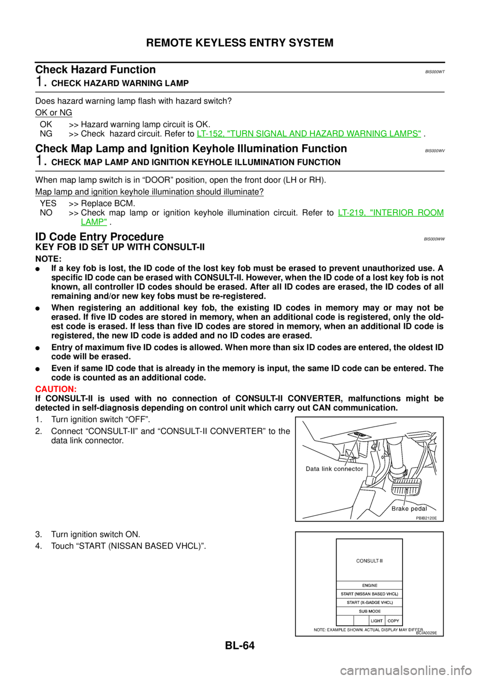
2. Connect “CONSULT-II” and “CONSULT-II CONVERTER” to the
data link connector.
3. Turn ignition switch ON.
4. Touch “START (NISSAN BASED VHCL)”.
PBIB2120E
BCIA0029E
Page 723 of 3502
REMOTE KEYLESS ENTRY SYSTEM
BL-65
C
D
E
F
G
H
J
K
L
MA
B
BL
5. Touch "BCM" on "SELECT SYSTEM" screen.
6. Touch “MULTI REMOTE ENT”.
7. Touch “WORK SUPPORT”.
8. The items are shown on the figure can be set up.
�“REMO CONT ID CONFIR”
Use this mode to confirm if a key fob ID code is registered or
not.
�“REMO CONT ID REGIST”
Use this mode to register a key fob ID code.
NOTE:
Register the ID code when key fob or BCM is replaced, or
when additional key fob is required.
�“REMO CONT ID ERASUR”
Use this mode to erase a key fob ID code.
BCIA0030E
PIIB0596E
BCIA0031E
LIIA0207E
Page 724 of 3502
BL-66
REMOTE KEYLESS ENTRY SYSTEM
KEY FOB ID SET UP WITHOUT CONSULT-II
PIIA2839E
Page 725 of 3502

REMOTE KEYLESS ENTRY SYSTEM
BL-67
C
D
E
F
G
H
J
K
L
MA
B
BL
NOTE:
�If a key fob is lost, the ID code of the lost key fob must be erased to prevent unauthorized use. A specific
ID code can be erased with CONSULT-II. However, when the ID code of a lost key fob is not known, all
controller ID codes should be erased. After all ID codes are erased, the ID codes of all remaining and/or
new key fobs must be re-registered.
To erase all ID codes in memory, register one ID code (key fob) five times. After all ID codes are erased,
the ID codes of all remaining and/or new key fobs must be re-registered.
�When registering an additional key fob, the existing ID codes in memory may or may not be erased. If five
ID codes are stored in memory, when an additional code is registered, only the oldest code is erased. If
less than five ID codes are stored in memory, when an additional ID code is registered, the new ID code is
added and no ID codes are erased.
�If you need to activate more than two additional new key fobs, repeat the procedure “Additional ID code
entry” for each new key fob.
�Entry of maximum five ID codes is allowed. When more than six ID codes are entered, the oldest ID code
will be erased.
�Even if same ID code that is already in the memory is input, the same ID code can be entered. The code
is counted as an additional code.
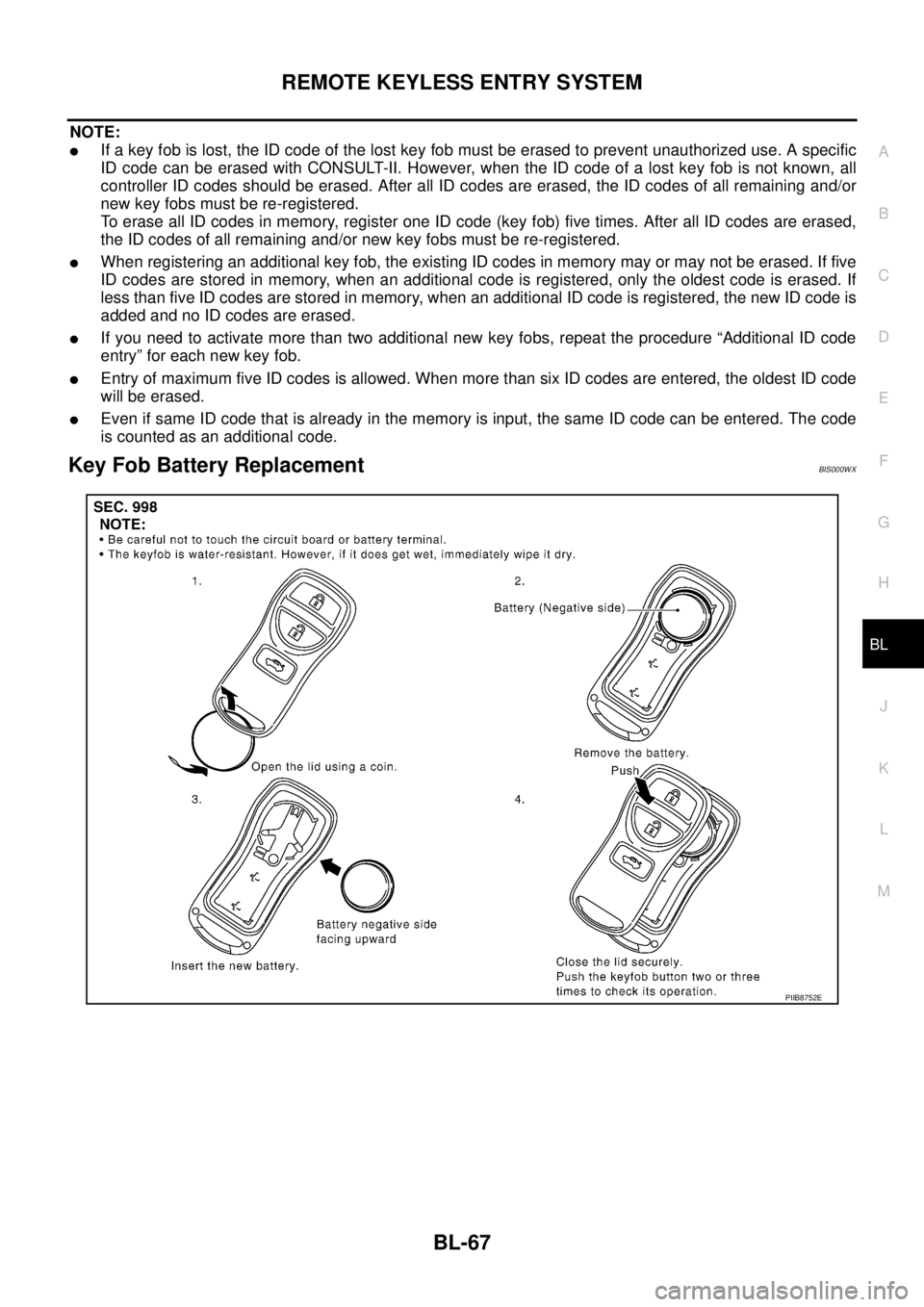
Key Fob Battery ReplacementBIS000WX
PIIB8752E
Page 726 of 3502
BL-68
INTELLIGENT KEY SYSTEM
INTELLIGENT KEY SYSTEMPFP:285e2
Component Parts and Harness Connector LocationBIS000WY
1. BCM
M3, M4, M52. IPDM E/R
E8,E93. A: Steering lock unit M21
B: Ignition knob switch, key switch
and key lock solenoid M20
4. Front door lock assembly (driver
side) (door unlock sensor) D245. Trunk lid lock assembly (trunk room
lamp switch) T76. Front door switch (driver side) B10
7. Rear door switch LH B14 8. Intelligent Key unit M31
(View with glove box removed)
PIIB8791E
Page 727 of 3502
INTELLIGENT KEY SYSTEM
BL-69
C
D
E
F
G
H
J
K
L
MA
B
BL
9. Antenna
10. Outside key antenna and front
door request switch (driver side)
D2511. Trunk open request switch
T212. Intelligent Key warning buzzer
(driver side) D22
(View with inside of driver door)
13. Intelligent Key warning buzzer
(Trunk room) B222
(View with trunk room RH)14. Unified meter and A/C AMP.
M41, M42
(View with A/C & AV switch removed)
PIIB8792E