Page 14 of 3502
 “AIR BAG” and “SEAT
BELT PRE-TENSIONER”
BCS000ZE
The Supplemental Restraint System such as “AIR B")
AT-6
PRECAUTIONS
PRECAUTIONSPFP:00001
Precautions for Supplemental Restraint System (SRS) “AIR BAG” and “SEAT
BELT PRE-TENSIONER”
BCS000ZE
The Supplemental Restraint System such as “AIR BAG” and “SEAT BELT PRE-TENSIONER”, used along
with a front seat belt, helps to reduce the risk or severity of injury to the driver and front passenger for certain
types of collision. Information necessary to service the system safely is included in the SRS and SB section of
this Service Manual.
WARNING:
�To avoid rendering the SRS inoperative, which could increase the risk of personal injury or death
in the event of a collision which would result in air bag inflation, all maintenance must be per-
formed by an authorized NISSAN/INFINITI dealer.
�Improper maintenance, including incorrect removal and installation of the SRS, can lead to per-
sonal injury caused by unintentional activation of the system. For removal of Spiral Cable and Air
Bag Module, see the SRS section.
�Do not use electrical test equipment on any circuit related to the SRS unless instructed to in this
Service Manual. SRS wiring harnesses can be identified by yellow and/or orange harnesses or
harness connectors.
Precautions Necessary for Steering Wheel Rotation After Battery DisconnectBCS000ZF
NOTE:
�This Procedure is applied only to models with Intelligent Key system and NATS (NISSAN ANTI-THEFT
SYSTEM).
�Remove and install all control units after disconnecting both battery cables with the ignition knob in the
″LOCK″ position.
�Always use CONSULT-II to perform self-diagnosis as a part of each function inspection after finishing
work. If DTC is detected, perform trouble diagnosis according to self-diagnostic results.
For models equipped with the Intelligent Key system and NATS, an electrically controlled steering lock mech-
anism is adopted on the key cylinder.
For this reason, if the battery is disconnected or if the battery is discharged, the steering wheel will lock and
steering wheel rotation will become impossible.
If steering wheel rotation is required when battery power is interrupted, follow the procedure below before
starting the repair operation.
OPERATION PROCEDURE
1. Connect both battery cables.
NOTE:
Supply power using jumper cables if battery is discharged.
2. Use the Intelligent Key or mechanical key to turn the ignition switch to the ″ACC″ position. At this time, the
steering lock will be released.
3. Disconnect both battery cables. The steering lock will remain released and the steering wheel can be
rotated.
4. Perform the necessary repair operation.
5. When the repair work is completed, return the ignition switch to the ″LOCK″ position before connecting
the battery cables. (At this time, the steering lock mechanism will engage.)
6. Perform a self-diagnosis check of all control units using CONSULT-II.
Page 46 of 3502
AT-38
TROUBLE DIAGNOSIS
DIAGNOSTIC WORKSHEET
Information From Customer
KEY POINTS
�WHAT..... Vehicle & A/T models
�WHEN..... Date, Frequencies
�WHERE..... Road conditions
�HOW..... Operating conditions, Symptoms
Customer name MR/MS Model & Year VIN
Trans. model Engine Mileage
Malfunction Date Manuf. Date In Service Date
Frequency❏ Continuous❏ Intermittent ( times a day)
Symptoms❏ Vehicle does not move. (❏ Any position❏ Particular position)
❏ No up-shift (❏ 1st → 2nd❏ 2nd → 3rd❏ 3rd → 4th)
❏ No down-shift (❏ 4th → 3rd❏ 3rd → 2nd❏ 2nd → 1st)
❏ Lock-up malfunction
❏ Shift point too high or too low.
❏ Shift shock or slip (❏ N → D❏ Lock-up❏ Any drive position)
❏ Noise or vibration
❏ No kick down
❏ No pattern select
❏ Others
()
Page 224 of 3502
AT-216
A/T SHIFT LOCK SYSTEM
A/T SHIFT LOCK SYSTEMPFP:34950
DescriptionBCS0014Z
�The electrical key interlock mechanism also operates as a shift lock:
With the ignition switch turned to ON, selector lever cannot be shifted from “P” to any other position unless
brake pedal is depressed.
With the key removed, selector lever cannot be shifted from “P” to any other position.
The key cannot be removed unless selector lever is placed in “P”.
�The shift lock and key interlock mechanisms are controlled by the ON-OFF operation of the shift lock sole-
noid and by the operation of the rotator and slider located inside key cylinder, respectively.
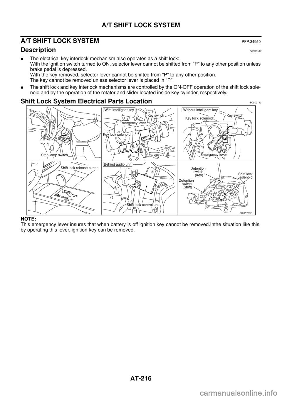
Shift Lock System Electrical Parts LocationBCS00150
NOTE:
This emergency lever insures that when battery is off ignition key cannot be removed.Inthe situation like this,
by operating this lever, ignition key can be removed.
SCIA5729E
Page 225 of 3502
A/T SHIFT LOCK SYSTEM
AT-217
D
E
F
G
H
I
J
K
L
MA
B
AT
Wiring Diagram — AT — SHIFTBCS00151
WITHOUT INTELLIGENT KEY
TCWM0523E
Page 227 of 3502
A/T SHIFT LOCK SYSTEM
AT-219
D
E
F
G
H
I
J
K
L
MA
B
AT
WITH INTELLIGENT KEY
TCWM0525E
Page 229 of 3502

A/T SHIFT LOCK SYSTEM
AT-221
D
E
F
G
H
I
J
K
L
MA
B
AT
Shift Lock Control Unit Reference ValuesBCS00152
SHIFT LOCK HARNESS CONNECTOR TERMINALS LAYOUT
SHIFT LOCK CONTROL UNIT INSPECTION TABLE
Data are reference values.
NOTE:
Make sure that the pointer swings only momentarily because the output time is so short. If the inspection is done with an oscilloscope, it
should be observed that the power source voltage lasts for 3.5 to 10 ms.
SCIA2004E
Terminal Wire color Item Condition Judgement standard
1 Y/R Power source Always Battery voltage
2LDetention switch (for
key)When selector lever is not in “P” position with
key inserted.Battery voltage
When selector lever is in “P” position with key
inserted.Approx. 0 V
3RDetention switch (for
shift)When selector lever is not “P” position. Battery voltage
When selector lever is “P” position. Approx. 0 V
4 R/G Stop lamp switchWhen brake pedal is depressed Battery voltage
When brake pedal is released Approx. 0 V
5V/WVehicle speed signal
(8pulse signal)Speed meter is operatedRefer to DI-12, "
Terminals and Ref-
erence Value for Combination
Meter" .
6 G Ignition switch signalIgnition switch: OFF Approx. 0 V
Ignition switch: ON Battery voltage
7 R/W Shift lock solenoid
�When selector lever is in “P” position, brake
pedal is depressed, and ignition switch is ON.
�When selector lever is not in “P” position,
ignition switch is ON, and vehicle speed is
10km/h or less.
�For 3minutes after selector lever is not in “P”
position, vehicle speed is 10 km/h or less,
and ignition switch is ON → OFF.Approx. 0 V
Except the above Battery voltage
8 B Ground Always Approx. 0 V
9 G/B Key lock solenoidWhen selector lever is not “P” position.Battery voltage for approx. 0.1 sec.
(Note)
When selector lever is “P” position. Approx. 0 V
10 G/WKey unlock solenoidWhen selector lever is “P” position with ignition
switch is OFF.Battery voltage for approx. 0.1 sec.
(Note)
When selector lever is not “P” position with igni-
tion switch is OFF.Approx. 0 V
Page 230 of 3502

AT-222
A/T SHIFT LOCK SYSTEM
Component InspectionBCS00153
SHIFT LOCK SOLENOID
Check operation by applying battery voltage to A/T device harness
connector terminal.
CAUTION:
Be sure to apply the voltage of the correct polarity to the
respective terminals. Otherwise, the part may be damaged.
DETENTION SWITCH (FOR KEY)
Check continuity between terminals of A/T device harness connector
terminals.
DETENTION SWITCH (FOR SHIFT)
Check continuity between terminals of A/T device harness connector
terminals.
KEY LOCK SOLENOID
Key Lock (With Intelligent Key)
Check operation by applying battery voltage to ignition knob switch,
key switch and key lock solenoid harness connector terminal.
CAUTION:
Be careful not to cause burnout of harness.
Connector Terminal
M62 9 (Battery voltage) - 10 (Ground)
SCIA6641E
Condition Connector Terminal Continuity
When selector lever is “P”
position.
M62 5 - 6No
When selector lever is not “P”
position.Ye s
SCIA6642E
Condition Connector Terminal Continuity
When selector lever is “P”
position.
M62 13 - 14No
When selector lever is not “P”
position.Ye s
SCIA6643E
Connector Terminal
M20 6 (Battery voltage) - 5 (Ground)
SCIA6645E
Page 231 of 3502

Check operation by applying battery voltage to key switch and key
lock solenoid harness connector terminal.")
A/T SHIFT LOCK SYSTEM
AT-223
D
E
F
G
H
I
J
K
L
MA
B
AT
Key Lock (Without Intelligent Key)
Check operation by applying battery voltage to key switch and key
lock solenoid harness connector terminal.
CAUTION:
Be careful not to cause burnout of harness.
Key Unlock (With Intelligent Key)
Check operation by applying battery voltage to ignition knob switch,
key switch and key lock solenoid harness connector terminal.
CAUTION:
Be careful not to cause burnout of harness.
Key Unlock (Without Intelligent Key)
Check operation by applying battery voltage to key switch and key
lock solenoid harness connector terminal.
CAUTION:
Be careful not to cause burnout of harness.
KEY SWITCH (WITHOUT INTELLIGENT KEY)
Check continuity between terminals of key switch and key lock sole-
noid harness connector terminals.
Connector Terminal
M34 6 (Battery voltage) - 5 (Ground)
SCIA6646E
Connector Terminal
M20 5 (Battery voltage) - 6 (Ground)
SCIA6647E
Connector Terminal
M34 5 (Battery voltage) - 6 (Ground)
SCIA6648E
Condition Connector Terminal Continuity
Key inserted
M34 1 - 4Ye s
Key withdrawn No
SCIA6650E