Page 2274 of 3502
EM-166
[VQ]
FRONT TIMING CHAIN CASE
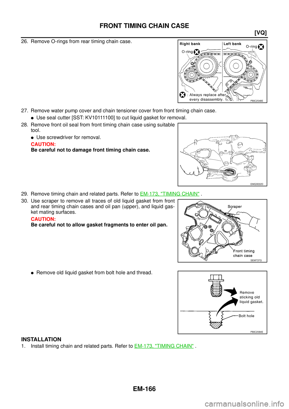
26. Remove O-rings from rear timing chain case.
27. Remove water pump cover and chain tensioner cover from front timing chain case.
�Use seal cutter [SST: KV10111100] to cut liquid gasket for removal.
28. Remove front oil seal from front timing chain case using suitable
tool.
�Use screwdriver for removal.
CAUTION:
Be careful not to damage front timing chain case.
29. Remove timing chain and related parts. Refer to EM-173, "
TIMING CHAIN" .
30. Use scraper to remove all traces of old liquid gasket from front
and rear timing chain cases and oil pan (upper), and liquid gas-
ket mating surfaces.
CAUTION:
Be careful not to allow gasket fragments to enter oil pan.
�Remove old liquid gasket from bolt hole and thread.
INSTALLATION
1. Install timing chain and related parts. Refer to EM-173, "TIMING CHAIN" .
PBIC2548E
EMQ0032D
SEM737G
PBIC2084E
Page 2275 of 3502
FRONT TIMING CHAIN CASE
EM-167
[VQ]
C
D
E
F
G
H
I
J
K
L
MA
EM
2. Hammer dowel pins (right and left) into front timing chain case
up to a point close to taper in order to shorten protrusion length.
3. Install new front oil seal on front timing chain case.
�Apply new engine oil to both oil seal lip and dust seal lip.
�Install it so that each seal lip is oriented as shown in the fig-
ure.
�Using suitable drift [outer diameter: 60 mm (2.36 in)], press-fit
oil seal until it becomes flush with front timing chain case end
face.
�Make sure the garter spring is in position and seal lip is not
inverted.
4. Install water pump cover and chain tensioner cover to front timing chain case.
�Apply a continuous bead of liquid gasket with tube presser
[SST: WS39930000] to front timing chain case as shown in
the figure.
Use Genuine Liquid Gasket or equivalent.
5. Install front timing chain case as follows:
PBIC2615E
SEM715A
PBIC0790E
SEM744GA
Page 2276 of 3502
EM-168
[VQ]
FRONT TIMING CHAIN CASE
a. Apply a continuous bead of liquid gasket with tube presser [SST:
WS39930000] to front timing chain case back side as shown in
the figure.
Use Genuine Liquid Gasket or equivalent.
b. Install new oil pan gasket.
�Apply liquid gasket to oil pan gasket as shown in the figure.
Use Genuine Liquid Gasket or equivalent.
�Align notch of front timing chain case with protrusion of oil pan
gasket.
PBIC2648E
PBIC2630E
PBIC1114E
Page 2277 of 3502
FRONT TIMING CHAIN CASE
EM-169
[VQ]
C
D
E
F
G
H
I
J
K
L
MA
EM
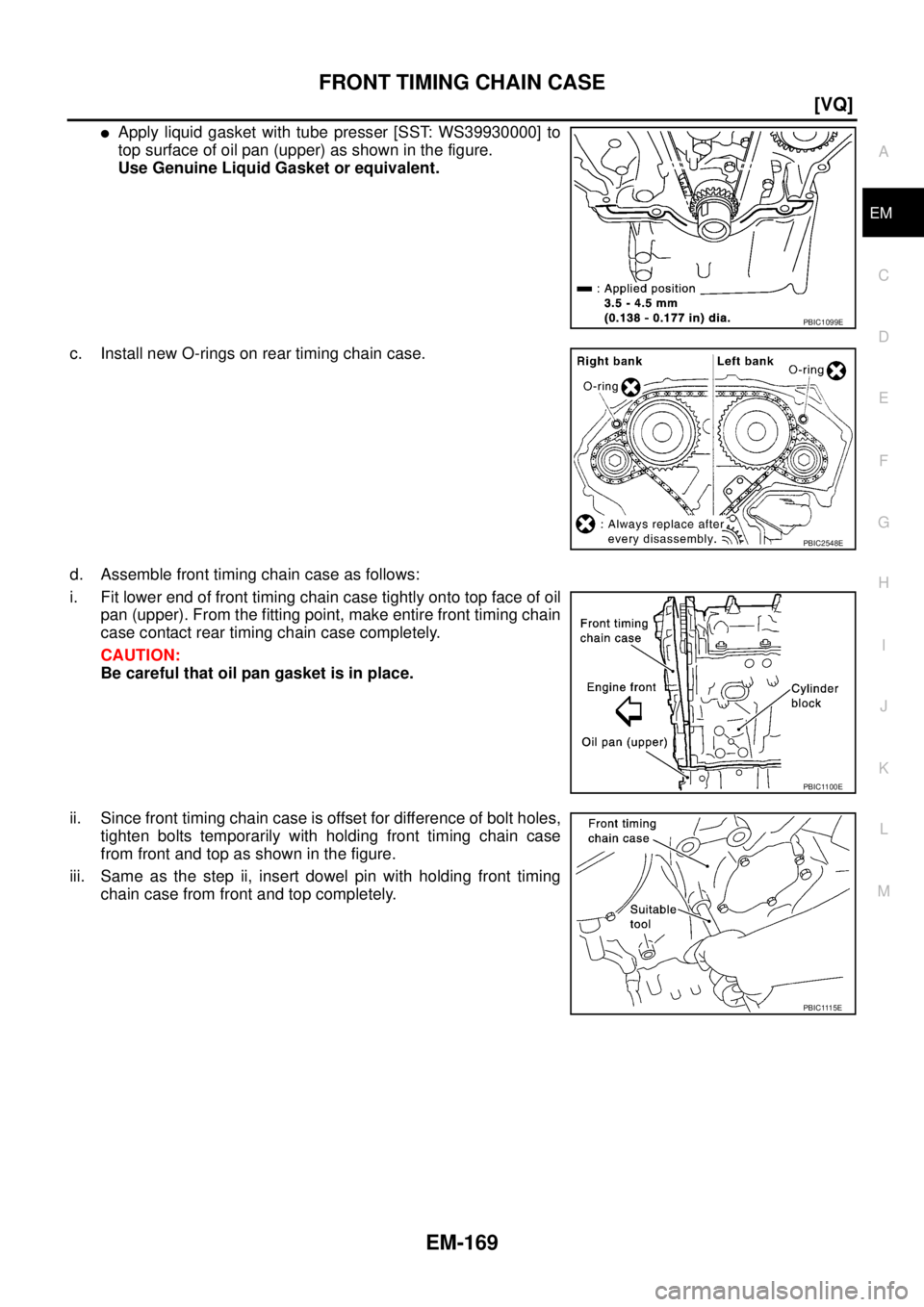
�Apply liquid gasket with tube presser [SST: WS39930000] to
top surface of oil pan (upper) as shown in the figure.
Use Genuine Liquid Gasket or equivalent.
c. Install new O-rings on rear timing chain case.
d. Assemble front timing chain case as follows:
i. Fit lower end of front timing chain case tightly onto top face of oil
pan (upper). From the fitting point, make entire front timing chain
case contact rear timing chain case completely.
CAUTION:
Be careful that oil pan gasket is in place.
ii. Since front timing chain case is offset for difference of bolt holes,
tighten bolts temporarily with holding front timing chain case
from front and top as shown in the figure.
iii. Same as the step ii, insert dowel pin with holding front timing
chain case from front and top completely.
PBIC1099E
PBIC2548E
PBIC1100E
PBIC1115E
Page 2278 of 3502
![NISSAN TEANA 2003 Service Manual EM-170
[VQ]
FRONT TIMING CHAIN CASE
e. Tighten mounting bolts to the specified torque in numerical order
as shown in the figure.
�There are two types of mounting bolt. Refer to the following
for loc](/manual-img/5/57392/w960_57392-2277.png "NISSAN TEANA 2003 Service Manual EM-170
[VQ]
FRONT TIMING CHAIN CASE
e. Tighten mounting bolts to the specified torque in numerical order
as shown in the figure.
�There are two types of mounting bolt. Refer to the following
for loc")
EM-170
[VQ]
FRONT TIMING CHAIN CASE
e. Tighten mounting bolts to the specified torque in numerical order
as shown in the figure.
�There are two types of mounting bolt. Refer to the following
for locating bolts.
f. After all bolts tightening, retighten them to the specified torque in
numerical order as shown in the figure.
6. Install engine mounting bracket (RH) and engine mounting insulator (RH). Refer to EM-223, "
ENGINE
ASSEMBLY" .
7. Remove jack which supports the oil pan (lower) bottom.
8. Remove oil pan (lower).
9. Install two mounting bolts in front of oil pan (upper) in numerical
order as shown in the figure.
10. Install oil pan (lower). Refer to EM-145, "
OIL PAN AND OIL STRAINER" .
11. Install right and left intake valve timing control covers as follows:
a. Install new seal rings in shaft grooves.
b. Apply a continuous bead of liquid gasket with tube presser [SST:
WS39930000] to intake valve timing control covers as shown in
the figure.
Use Genuine Liquid Gasket or equivalent.
c. Install new collared O-rings in front timing chain case oil holes
(left and right sides).
d. Being careful not to move seal rings from the installation grooves, align dowel pins on front timing chain
case with the holes to install intake valve timing control covers.M8 bolts : 1, 2
: 28.4 N·m (2.9 kg-m, 21 ft-lb)
M6 bolts : Except the above
: 12.7 N·m (1.3 kg-m, 9 ft-lb)
: 17.2 N·m (1.8 kg-m, 13 ft-lb)
SEM730G
PBIC1637E
SBIA0492E
PBIC2631E
Page 2279 of 3502
![NISSAN TEANA 2003 Service Manual FRONT TIMING CHAIN CASE
EM-171
[VQ]
C
D
E
F
G
H
I
J
K
L
MA
EM
e. Tighten mounting bolts in numerical order as shown in the fig-
ure.
12. Install crankshaft pulley as follows:
a. Install crankshaft p](/manual-img/5/57392/w960_57392-2278.png "NISSAN TEANA 2003 Service Manual FRONT TIMING CHAIN CASE
EM-171
[VQ]
C
D
E
F
G
H
I
J
K
L
MA
EM
e. Tighten mounting bolts in numerical order as shown in the fig-
ure.
12. Install crankshaft pulley as follows:
a. Install crankshaft p")
FRONT TIMING CHAIN CASE
EM-171
[VQ]
C
D
E
F
G
H
I
J
K
L
MA
EM
e. Tighten mounting bolts in numerical order as shown in the fig-
ure.
12. Install crankshaft pulley as follows:
a. Install crankshaft pulley, taking care not to damage front oil seal.
�When press-fitting crankshaft pulley with plastic hammer, tap on its center portion (not circumference).
b. Fix crankshaft with pulley holder [SST: KV10109300].
c. Tighten crankshaft pulley bolt.
d. Place a matching mark (A) on crank pulley (1) aligning with the
matching (B) of crank pulley mounting bolt (2). Tighten the bolts
90 degrees (one marks).
e. Rotate crankshaft pulley in normal direction (clockwise when viewed from engine front) to confirm it turns
smoothly.
13. For the following operations, perform steps in the reverse order of removal.
INSPECTION AFTER INSTALLATION
Inspection for Leaks
The following are procedures for checking fluid leak, lubricates leak and exhaust gases leak.
�Before starting engine, check oil/fluid levels including engine coolant and engine oil. If less than required
quantity, fill to the specified level. Refer to MA-14, "
RECOMMENDED FLUIDS AND LUBRICANTS" .
�Run engine to check for unusual noise and vibration.
NOTE:
If hydraulic pressure inside timing chain tensioner drops after removal/installation, slack in the guide may
generate a pounding noise during and just after engine start. However, this is normal. Noise will stop after
hydraulic pressure rises.
�Warm up engine thoroughly to make sure there is no leakage of exhaust gases, or any oil/fluids including
engine oil and engine coolant.
�Bleed air from lines and hoses of applicable lines, such as in cooling system.
�After cooling down engine, again check oil/fluid levels including engine oil and engine coolant. Refill to the
specified level, if necessary.
PBIC0918E
: 44.1 N·m (4.5 kg-m, 33 ft-lb)
PBIC4627J
Page 2281 of 3502
TIMING CHAIN
EM-173
[VQ]
C
D
E
F
G
H
I
J
K
L
MA
EM
TIMING CHAINPFP:13028
Removal and InstallationBBS004W0
PBIC2476E
Page 2282 of 3502
![NISSAN TEANA 2003 Service Manual EM-174
[VQ]
TIMING CHAIN
NOTE:
�This section describes procedures for removal/installation front timing chain case and timing chain related
parts, and rear timing chain case, when oil pan (upper) ne](/manual-img/5/57392/w960_57392-2281.png "NISSAN TEANA 2003 Service Manual EM-174
[VQ]
TIMING CHAIN
NOTE:
�This section describes procedures for removal/installation front timing chain case and timing chain related
parts, and rear timing chain case, when oil pan (upper) ne")
EM-174
[VQ]
TIMING CHAIN
NOTE:
�This section describes procedures for removal/installation front timing chain case and timing chain related
parts, and rear timing chain case, when oil pan (upper) needs to be removed/installed for engine overhaul,
etc.
�To removal/installation front timing chain case, timing chain, and timing chain related parts without remov-
ing oil pan (upper), refer to EM-163, "
FRONT TIMING CHAIN CASE" .
REMOVAL
1. Remove engine assembly from vehicle, and separate front suspension member and transaxle from
engine. Refer to EM-223, "
ENGINE ASSEMBLY" .
2. Install engine sub-attachment with engine stand shaft [SST: KV10117001 and KV10106500] to right side
of cylinder block, then lift engine, and mount it onto engine stand [SST: ST0501S000]. Refer to EM-228,
"CYLINDER BLOCK" .
3. Drain engine oil. Refer to LU-21, "
Changing Engine Oil" .
4. Drain engine coolant from inside engine. Refer to EM-229, "
DISASSEMBLY" .
5. Remove intake manifold collectors (upper and lower). Refer to EM-133, "
INTAKE MANIFOLD COLLEC-
TOR" .
6. Remove rocker covers (right and left banks). Refer to EM-160, "
ROCKER COVER" .
7. Remove oil pans (lower and upper) and oil strainer. Refer to EM-145, "
OIL PAN AND OIL STRAINER" .
8. Remove idler pulley and bracket.
9. Separate engine harness removing their brackets from front timing chain case
10. Remove right and left intake valve timing control covers.
�Loosen mounting bolts in the reverse order as shown in the
figure.
�U s e s e a l c u t t e r [ S S T: K V 1 0 1111 0 0 ] t o c u t l i q u i d g a s k e t f o r
removal.
CAUTION:
Shaft is internally jointed with camshaft sprocket (INT) cen-
ter hole. When removing, keep it horizontal until it is com-
pletely disconnected.
11. Remove collared O-ring from front timing chain case oil hole (left
and right sides).
1. O-ring 2. Timing chain tensioner (secondary) 3. Internal chain guide
4. Timing chain tensioner (secondary) 5. Camshaft sprocket (EXH) 6. Timing chain (secondary)
7. Timing chain (primary) 8. Camshaft sprocket (INT) 9. Slack guide
10. Timing chain tensioner (primary) 11. Camshaft sprocket (EXH) 12. Timing chain (secondary)
13. Camshaft sprocket (INT) 14. Crankshaft sprocket 15. Collared O-ring
16. Seal ring 17. Intake valve timing control cover 18. Chain tensioner cover
19. Intake valve timing control cover 20. Water pump cover 21. Front oil seal
22. Crankshaft pulley 23. Idler pulley 24. Idler pulley bracket
25. Center shaft 26. Washer 27. Front timing chain case
28. Rear timing chain case 29. Water drain plug (front) 30. Tension guide
PBIC0918E
PBIC2631E
![NISSAN TEANA 2003 Service Manual FRONT TIMING CHAIN CASE
EM-167
[VQ]
C
D
E
F
G
H
I
J
K
L
MA
EM
2. Hammer dowel pins (right and left) into front timing chain case
up to a point close to taper in order to shorten protrusion length.
3](/manual-img/5/57392/w960_57392-2274.png "NISSAN TEANA 2003 Service Manual FRONT TIMING CHAIN CASE
EM-167
[VQ]
C
D
E
F
G
H
I
J
K
L
MA
EM
2. Hammer dowel pins (right and left) into front timing chain case
up to a point close to taper in order to shorten protrusion length.
3")
![NISSAN TEANA 2003 Service Manual EM-168
[VQ]
FRONT TIMING CHAIN CASE
a. Apply a continuous bead of liquid gasket with tube presser [SST:
WS39930000] to front timing chain case back side as shown in
the figure.
Use Genuine Liquid Ga](/manual-img/5/57392/w960_57392-2275.png "NISSAN TEANA 2003 Service Manual EM-168
[VQ]
FRONT TIMING CHAIN CASE
a. Apply a continuous bead of liquid gasket with tube presser [SST:
WS39930000] to front timing chain case back side as shown in
the figure.
Use Genuine Liquid Ga")
![NISSAN TEANA 2003 Service Manual TIMING CHAIN
EM-173
[VQ]
C
D
E
F
G
H
I
J
K
L
MA
EM
TIMING CHAINPFP:13028
Removal and InstallationBBS004W0
PBIC2476E](/manual-img/5/57392/w960_57392-2280.png "NISSAN TEANA 2003 Service Manual TIMING CHAIN
EM-173
[VQ]
C
D
E
F
G
H
I
J
K
L
MA
EM
TIMING CHAINPFP:13028
Removal and InstallationBBS004W0
PBIC2476E")