Page 2169 of 3502
![NISSAN TEANA 2003 Service Manual TIMING CHAIN
EM-61
[QR]
C
D
E
F
G
H
I
J
K
L
MA
EM
c. Apply a continuous bead of liquid gasket with tube presser [SST:
WS39930000] to intake valve timing control cover as shown in
the figure.
Use Gen](/manual-img/5/57392/w960_57392-2168.png "NISSAN TEANA 2003 Service Manual TIMING CHAIN
EM-61
[QR]
C
D
E
F
G
H
I
J
K
L
MA
EM
c. Apply a continuous bead of liquid gasket with tube presser [SST:
WS39930000] to intake valve timing control cover as shown in
the figure.
Use Gen")
TIMING CHAIN
EM-61
[QR]
C
D
E
F
G
H
I
J
K
L
MA
EM
c. Apply a continuous bead of liquid gasket with tube presser [SST:
WS39930000] to intake valve timing control cover as shown in
the figure.
Use Genuine Liquid Gasket or equivalent.
d. Tighten mounting bolts in numerical order as shown in the fig-
ure.
e. Install intake valve timing control solenoid valves to intake valve timing control cover if removed.
f. Connect ground cables, and install harness clip.
10. Insert crankshaft pulley by aligning with crankshaft key.
�When inserting crankshaft pulley with plastic hammer, tap on its center portion (not circumference).
CAUTION:
Install protecting front oil seal lip section from any damage.
11. Tighten crankshaft pulley bolt with the following procedure.
�Secure crankshaft pulley with pulley holder [SST: KV10109300], and tighten crankshaft pulley bolt.
a. Apply new engine oil to thread and seat surfaces of crankshaft pulley bolt.
b. Tighten crankshaft pulley bolt.
c. Put a paint mark on crankshaft pulley, mating with any one of six
easy to recognize angle marks on bolt flange.
d. Turn another 60 degrees clockwise (angle tightening).
�Check the tightening angle with movement of one angle mark.
12. Install all removed parts in the reverse order of removal.
NOTE:
If hydraulic pressure inside timing chain tensioner drops after removal/installation, slack in the guide may
generate a pounding noise during and just after engine start. However, this is normal. Noise will stop after
hydraulic pressure rises.
SBIA0260E
KBIA0085E
: 42.1 N·m (4.3 kg-m, 31 ft-lb)
SEM751G
Page 2170 of 3502
![NISSAN TEANA 2003 Service Manual EM-62
[QR]
OIL SEAL
OIL SEALPFP:12279
Removal and Installation of Valve Oil SealBBS00598
REMOVAL
1. Remove camshafts. Refer to EM-41, "CAMSHAFT" .
2. Remove valve lifters. Refer to EM-41, "
CAMSHAF](/manual-img/5/57392/w960_57392-2169.png "NISSAN TEANA 2003 Service Manual EM-62
[QR]
OIL SEAL
OIL SEALPFP:12279
Removal and Installation of Valve Oil SealBBS00598
REMOVAL
1. Remove camshafts. Refer to EM-41, \"CAMSHAFT\" .
2. Remove valve lifters. Refer to EM-41, \"
CAMSHAF")
EM-62
[QR]
OIL SEAL
OIL SEALPFP:12279
Removal and Installation of Valve Oil SealBBS00598
REMOVAL
1. Remove camshafts. Refer to EM-41, "CAMSHAFT" .
2. Remove valve lifters. Refer to EM-41, "
CAMSHAFT" .
3. Rotate crankshaft, and set piston whose valve oil seal is to be removed to TDC. This will prevent valve
from dropping into cylinder.
CAUTION:
When rotating crankshaft, be careful to avoid scarring front cover with timing chain.
4. Remove valve collet.
�Compress valve spring with valve spring compressor, attach-
ment and adapter (SST). Remove valve collet with magnet
hand.
CAUTION:
When working, be careful not to damage valve lifter holes.
5. Remove valve spring retainer and valve spring (with valve spring seat).
CAUTION:
Do not remove valve spring seat from valve spring.
6. Remove valve oil seal with valve oil seal puller (SST).
INSTALLATION
1. Apply new engine oil to new valve oil seal joint surface and seal lip.
2. Press in valve oil seal to the height “H” shown in the figure with
valve oil seal drift (SST).
3. Install in the reverse order of removal after this step.
PBIC1791E
SEM093F
Height “H” : 11.8 - 12.4 mm (0.465 - 0.488 in)
KBIA1999J
Page 2171 of 3502
OIL SEAL
EM-63
[QR]
C
D
E
F
G
H
I
J
K
L
MA
EM
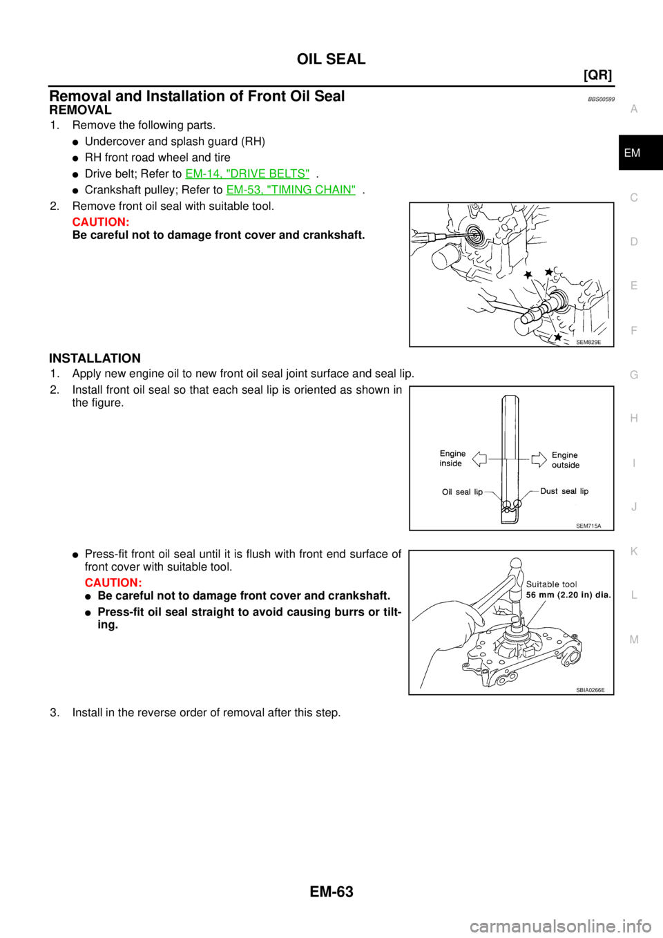
Removal and Installation of Front Oil SealBBS00599
REMOVAL
1. Remove the following parts.
�Undercover and splash guard (RH)
�RH front road wheel and tire
�Drive belt; Refer to EM-14, "DRIVE BELTS" .
�Crankshaft pulley; Refer to EM-53, "TIMING CHAIN" .
2. Remove front oil seal with suitable tool.
CAUTION:
Be careful not to damage front cover and crankshaft.
INSTALLATION
1. Apply new engine oil to new front oil seal joint surface and seal lip.
2. Install front oil seal so that each seal lip is oriented as shown in
the figure.
�Press-fit front oil seal until it is flush with front end surface of
front cover with suitable tool.
CAUTION:
�Be careful not to damage front cover and crankshaft.
�Press-fit oil seal straight to avoid causing burrs or tilt-
ing.
3. Install in the reverse order of removal after this step.
SEM829E
SEM715A
SBIA0266E
Page 2175 of 3502
![NISSAN TEANA 2003 Service Manual CYLINDER HEAD
EM-67
[QR]
C
D
E
F
G
H
I
J
K
L
MA
EM
NOTE:
Can be removed and installed even when assembled with cylinder head.
4. Remove front cover and timing chain. Refer to EM-53, "
TIMING CHAIN"](/manual-img/5/57392/w960_57392-2174.png "NISSAN TEANA 2003 Service Manual CYLINDER HEAD
EM-67
[QR]
C
D
E
F
G
H
I
J
K
L
MA
EM
NOTE:
Can be removed and installed even when assembled with cylinder head.
4. Remove front cover and timing chain. Refer to EM-53, \"
TIMING CHAIN\"")
CYLINDER HEAD
EM-67
[QR]
C
D
E
F
G
H
I
J
K
L
MA
EM
NOTE:
Can be removed and installed even when assembled with cylinder head.
4. Remove front cover and timing chain. Refer to EM-53, "
TIMING CHAIN" .
5. Remove camshafts. Refer to EM-41, "
CAMSHAFT" .
6. Remove cylinder head loosening bolts in reverse order as
shown in the figure.
�Using the following tool, loosen cylinder head bolts.
NOTE:
There are two types of cylinder head bolt because of parallel
manufacture.
7. Remove cylinder head gasket.
INSPECTION AFTER REMOVAL
Cylinder Head Bolts Outer Diameter
�Cylinder head bolts are tightened by plastic zone tightening
method. Whenever the size difference between “d1” and “d2”
exceeds the limit, replace them with a new one.
�If reduction of outer diameter appears in a position other than
“d2”, use it as “d2” point.
NOTE:
When replacing any cylinder head bolts, it is possible to use them
with mixing flange bolt and bolt with washer.
Cylinder Head Distortion
NOTE:
When performing this inspection, cylinder block distortion should be also checking. Refer to EM-102, "
CYLIN-
DER BLOCK DISTORTION" .
1. Wipe off engine oil and remove water scale (like deposit), gasket, sealant, carbon, etc. with scraper.
CAUTION:
Use utmost care not to allow gasket debris to enter passages for engine oil or engine coolant.
2. At each of several locations on bottom surface of cylinder head,
measure the distortion in six directions.
�If it exceeds the limit, replace cylinder head.Bolt with washer
: Hexagonal wrench [size 10 mm (0.39 in)]
Flange bolt
: TORX socket (size E20)
KBIA0058E
Limit (“d1” – “d2”): 0.23 mm (0.0091 in)
SBIA0269E
Limit : 0.1 mm (0.004 in)
PBIC0075E
Page 2231 of 3502
PREPARATION
EM-123
[VQ]
C
D
E
F
G
H
I
J
K
L
MA
EM
EM03470000
Piston ring compressorInstalling piston assembly into cylinder bore
ST16610001
Pilot bushing pullerRemoving pilot converter
KV10111100
Seal cutterRemoving oil pan (lower and upper), front
and rear timing chain case, etc.
WS39930000
Tube presserPressing the tube of liquid gasket
KV10109300
Pulley holderRemoving and installing crankshaft pulley
a: 68 mm (2.68 in)
b: 8 mm (0.31 in) dia.
KV10112100
Angle wrenchTightening bolts for bearing cap, cylinder
head, etc. in angle
KV10117100
Heated oxygen sensor wrenchLoosening or tightening heated oxygen
sensor 1
For 22 mm (0.87 in) width hexagon nut Tool number
Tool nameDescription
NT044
NT045
NT046
NT052
NT628
NT014
NT379
Page 2257 of 3502
![NISSAN TEANA 2003 Service Manual OIL PAN AND OIL STRAINER
EM-149
[VQ]
C
D
E
F
G
H
I
J
K
L
MA
EM
�To install, align protrusion of oil pan gasket with notches of
front timing chain case and rear oil seal retainer.
�Install oil pan ga](/manual-img/5/57392/w960_57392-2256.png "NISSAN TEANA 2003 Service Manual OIL PAN AND OIL STRAINER
EM-149
[VQ]
C
D
E
F
G
H
I
J
K
L
MA
EM
�To install, align protrusion of oil pan gasket with notches of
front timing chain case and rear oil seal retainer.
�Install oil pan ga")
OIL PAN AND OIL STRAINER
EM-149
[VQ]
C
D
E
F
G
H
I
J
K
L
MA
EM
�To install, align protrusion of oil pan gasket with notches of
front timing chain case and rear oil seal retainer.
�Install oil pan gasket with smaller arc to front timing chain
case side.
c. Install new O-rings on the bottom of cylinder block and oil pump.
d. Apply a continuous bead of liquid gasket with tube presser [SST:
WS39930000] to cylinder block mating surface of oil pan (upper)
to a limited portion as shown in the figure.
Use Genuine Liquid Gasket or equivalent.
CAUTION:
�For bolt holes with marks (5 locations), apply liquid
gasket outside the holes.
�Apply a bead of 4.5 to 5.5 mm (0.177 to 0.217 in) diameter
to area “A”.
�Attaching should be done within 5 minutes after coating.
e. Install oil pan (upper).
CAUTION:
Install avoiding misalignment of both oil pan gasket and O-rings.
�Tighten bolts in numerical order as shown in the figure.
�There are two types of mounting bolt. Refer to the following
for locating bolts.
f. Install transaxle joint bolts.
2. Install oil strainer to oil pump.
3. Install oil pan (lower) as follows:
PBIC1145E
PBIC1144E
PBIC2300E
M8 × 100 mm (3.97 in) : 5, 7, 8, 11
M8 × 25 mm (0.98 in) : Except the above
PBIC1636E
Page 2271 of 3502
![NISSAN TEANA 2003 Service Manual FRONT TIMING CHAIN CASE
EM-163
[VQ]
C
D
E
F
G
H
I
J
K
L
MA
EM
FRONT TIMING CHAIN CASEPFP:13599
Removal and InstallationBBS004VZ
NOTE:
�This section describes removal/installation procedure of front](/manual-img/5/57392/w960_57392-2270.png "NISSAN TEANA 2003 Service Manual FRONT TIMING CHAIN CASE
EM-163
[VQ]
C
D
E
F
G
H
I
J
K
L
MA
EM
FRONT TIMING CHAIN CASEPFP:13599
Removal and InstallationBBS004VZ
NOTE:
�This section describes removal/installation procedure of front")
FRONT TIMING CHAIN CASE
EM-163
[VQ]
C
D
E
F
G
H
I
J
K
L
MA
EM
FRONT TIMING CHAIN CASEPFP:13599
Removal and InstallationBBS004VZ
NOTE:
�This section describes removal/installation procedure of front timing chain case and timing chain related
parts without removing oil pan (upper) on vehicle.
�When oil pan (upper) needs to be removed or installed, or when rear timing chain case is removed or
installed, remove oil pans (lower and upper) first. Then remove front timing chain case, timing chain
related parts, and rear timing chain case in this order, and install in the reverse order of removal. Refer to
EM-173, "
TIMING CHAIN" .
�Refer to EM-173, "TIMING CHAIN" for component parts location.
REMOVAL
1. Remove engine cover. Refer to EM-133, "INTAKE MANIFOLD COLLECTOR" .
2. Remove air duct (inlet), air cleaner case (upper) with mass air flow sensor and air duct assembly. Refer to
EM-131, "
AIR CLEANER AND AIR DUCT" .
3. Remove undercover and splash guard (RH).
4. Remove right side front road wheel and tire.
5. Drain engine oil. Refer to LU-21, "
Changing Engine Oil" .
CAUTION:
�Perform this step when engine is cold.
�Do not spill engine oil on drive belts.
6. Drain engine coolant from radiator. Refer to CO-34, "
Changing Engine Coolant" .
CAUTION:
�Perform this step when engine is cold.
�Do not spill engine coolant on drive belts.
7. Remove intake manifold collectors (upper and lower). Refer to EM-133, "
INTAKE MANIFOLD COLLEC-
TOR" .
8. Remove drive belts. Refer to EM-128, "
DRIVE BELTS" .
9. Remove alternator. Refer to SC-27, "
CHARGING SYSTEM" .
10. Remove power steering oil pump from bracket with piping connected, and temporarily secure it to aside.
Refer to PS-29, "
POWER STEERING OIL PUMP" .
11. Remove power steering oil pump bracket. Refer to PS-29, "
POWER STEERING OIL PUMP" .
12. Remove idler pulley and bracket. Refer to EM-173, "
TIMING CHAIN" .
13. Separate engine harnesses removing their brackets from front timing chain case.
14. Remove rocker covers (right and left bank). Refer to EM-160, "
ROCKER COVER" .
NOTE:
When only timing chain (primary) is removed, rocker cover does not need to be removed.
15. Obtain No. 1 cylinder at TDC of its compression stroke as follows:
NOTE:
When timing chain is not removed/installed, this step is not required.
a. Rotate crankshaft pulley clockwise to align timing mark (grooved
line without color) with timing indicator.
SEM918G
Page 2272 of 3502
![NISSAN TEANA 2003 Service Manual EM-164
[VQ]
FRONT TIMING CHAIN CASE
b. Make sure that intake and exhaust cam noses on No. 1 cylinder
(engine front side of right bank) are located as shown in the fig-
ure.
�If not, turn crankshaft](/manual-img/5/57392/w960_57392-2271.png "NISSAN TEANA 2003 Service Manual EM-164
[VQ]
FRONT TIMING CHAIN CASE
b. Make sure that intake and exhaust cam noses on No. 1 cylinder
(engine front side of right bank) are located as shown in the fig-
ure.
�If not, turn crankshaft")
EM-164
[VQ]
FRONT TIMING CHAIN CASE
b. Make sure that intake and exhaust cam noses on No. 1 cylinder
(engine front side of right bank) are located as shown in the fig-
ure.
�If not, turn crankshaft one revolution (360 degrees) and align
as shown in the figure.
NOTE:
When only timing chain (primary) is removed, rocker cover does
not need to be removed. To make sure that No. 1 cylinder is at
its compression TDC, remove front timing chain case first. Then
check mating marks on camshaft sprockets. Refer to EM-181,
"INSTALLATION" .
16. Remove crankshaft pulley as follows:
a. Fix crankshaft with pulley holder (SST).
b. Loosen crankshaft pulley bolt and locate bolt seating surface at
10 mm (0.39 in) from its original position.
CAUTION:
Do not remove crankshaft pulley bolt as it will be used as a
supporting point for suitable puller.
c. Place suitable puller tab on holes of crankshaft pulley, and pull
crankshaft pulley through.
CAUTION:
Do not put suitable puller tab on crankshaft pulley periph-
ery, as this will damage internal damper.
17. Remove oil pan (lower). Refer to EM-145, "
OIL PAN AND OIL STRAINER" .
18. Loosen two mounting bolts in front of oil pan (upper) in the
reverse order as shown in the figure.
19. Install oil pan (lower) temporarily.
�Applying liquid gasket is unnecessary.
20. Support the oil pan (lower) bottom with jack.
�Perform following operations with engine front side supported with jack.
CAUTION:
Put a piece of wood or something similar as the supporting surface, be careful not to damage oil
pan (lower).
21. Remove right and left intake valve timing control covers.
SEM418G
PBIC2475E
SEM915E
PBIC1637E
![NISSAN TEANA 2003 Service Manual PREPARATION
EM-123
[VQ]
C
D
E
F
G
H
I
J
K
L
MA
EM
EM03470000
Piston ring compressorInstalling piston assembly into cylinder bore
ST16610001
Pilot bushing pullerRemoving pilot converter
KV10111100
Se](/manual-img/5/57392/w960_57392-2230.png "NISSAN TEANA 2003 Service Manual PREPARATION
EM-123
[VQ]
C
D
E
F
G
H
I
J
K
L
MA
EM
EM03470000
Piston ring compressorInstalling piston assembly into cylinder bore
ST16610001
Pilot bushing pullerRemoving pilot converter
KV10111100
Se")